Transformer Grounding: Testing Best Practices
Transformer grounding is critical for safety and performance. It ensures fault currents are safely managed, stabilizes voltage, and protects equipment and personnel. Testing verifies proper installation and compliance with standards like the NEC. Here's what you need to know:
- Purpose of Grounding: Prevents shocks, stabilizes voltage, and protects against faults.
- Importance of Testing: Detects hidden issues like loose connections or improper bonding.
- NEC Guidelines: Specifies conductor sizing, resistance thresholds, and acceptable materials.
- Testing Methods: Includes grounding resistance (fall-of-potential), insulation resistance, and continuity checks.
- Maintenance: Regular inspections and testing are necessary to ensure long-term reliability.
Transformer Grounding Testing Step-by-Step Process and NEC Requirements
Ground Resistance Measurement, NEC 2014 - [250.53(A)(2)], (26min:27sec)
sbb-itb-501186b
NEC Requirements for Grounding Systems
The National Electrical Code (NEC) outlines specific guidelines for grounding transformers and related equipment to ensure safety for both people and property. According to NEC Article 100, transformers - classified as separately derived systems - must have a dedicated bonding jumper and grounding electrode conductor connected to a local grounding electrode system. These measures are designed to create a low-impedance fault path and reduce the risk of hazardous touch voltages. Let’s break down the NEC’s requirements for conductor sizing and resistance levels.
Grounding Electrode Conductor Sizing
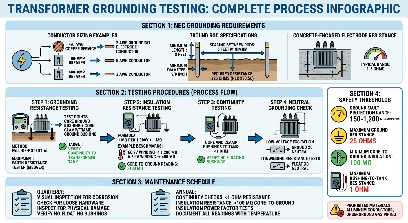
The NEC provides detailed guidance for sizing grounding electrode conductors in Table 250.66, which bases the size on the service entrance conductor. For instance, if you’re working with a 4/0 AWG copper service conductor, you’ll need a 2 AWG copper grounding electrode conductor. Similarly, equipment grounding conductors are sized according to Table 250.122, which depends on the rating of the overcurrent device. For example:
- A 100‑amp breaker requires an 8 AWG conductor.
- A 400‑amp breaker calls for a 3 AWG conductor.
NEC 250.50 also mandates that all available grounding electrodes at a structure - such as rebar encased in concrete (commonly referred to as Ufer grounds), metal water pipes, and ground rings - be bonded into one cohesive grounding system. However, certain materials like underground metal gas piping and aluminum conductors are prohibited as grounding electrodes because they are prone to corrosion. Among the options, concrete-encased electrodes are often the most effective, with resistance values typically ranging between 1 and 5 ohms.
While proper conductor sizing is essential, ensuring low resistance in the grounding system is equally important.
Grounding Resistance Thresholds
Ground rods must meet the NEC’s requirement of having an earth resistance of 25 ohms or less, as specified in NEC 250.56. If a single ground rod fails to meet this standard, an additional electrode must be installed. To meet these requirements:
- Ground rods should be at least 8 feet long and have a minimum diameter of 5/8 inch.
- When installing multiple rods, they must be spaced at least 6 feet apart to ensure effectiveness.
This 25-ohm limit ensures that fault currents are sufficient to trip breakers or blow fuses quickly. To verify compliance, ground rod resistance should be tested using the fall-of-potential method, as outlined in IEEE Standard 81, before the area is backfilled. Ground fault protection devices, which typically have adjustable thresholds ranging from 150 to 1,200 milliamperes, play a crucial role in maintaining safety. Meeting these resistance and testing standards is critical for ensuring a reliable and safe grounding system, as will be further discussed in later sections.
Grounding System Testing Procedures
After sizing your conductors and installing grounding electrodes according to NEC requirements, the next step is confirming that your system performs as intended. Testing your grounding system during transformer installation ensures fault currents are safely managed, protecting equipment from hazardous voltage levels.
How to Test Grounding Resistance
The fall-of-potential method is widely used to measure grounding resistance. This test requires an earth resistance tester (commonly called a ground tester or megger). To perform it, place two auxiliary stakes at specific distances from your ground electrode and measure the resistance between them.
For transformers, grounding verification involves two auxiliary bushings: the Core Ground Bushing, which grounds the magnetic core, and the Core Clamp/Frame Ground Bushing, which grounds the structural frame. After installation or maintenance, confirm proper grounding by measuring continuity between these bushings and the transformer tank.
"Both the core ground and core clamp ground bushings should be connected to earth ground during normal transformer operation."
Once resistance is verified, insulation testing is the next step to ensure the system's overall integrity.
Insulation Resistance and Continuity Testing
Insulation resistance testing identifies potential issues in transformer insulation before they escalate into safety risks. A general rule for safe energization is 1 MΩ per 1,000 V of applied test voltage, plus an additional 1 MΩ. For instance, a 66 kV winding at 68°F (20°C) should measure around 1,200 MΩ, while a 6.6 kV winding should show approximately 400 MΩ. These benchmarks align with NEC and IEEE standards.
Before testing, disconnect all high-voltage, low-voltage, neutral connections, lightning arresters, and meters. Group bushings of the same voltage level together with jumpers to test the entire winding. Never conduct insulation resistance tests while the transformer is under vacuum, as this could cause flashover. Always record the ambient temperature to adjust readings to a standard 68°F (20°C) for historical comparison.
When shorting low-side bushings (X1–X2–X3), connect a jumper from X3 back to X1. This creates a redundant path, reducing the risk of incomplete shorts caused by high-resistance connections. For core-to-ground Megger tests, readings should exceed 100 MΩ, confirming proper isolation of the core from the tank, except at the designated grounding point.
Core Ground and Neutral Grounding Resistor Testing
In addition to resistance and insulation testing, core and neutral resistor evaluations are essential for transformer safety. These tests build on earlier assessments to provide a thorough grounding system evaluation.
The neutral bushing (X0) requires specific handling depending on the test. For low-voltage excitation tests, ground the neutral to establish a stable reference point and prevent it from floating. However, for turns ratio (TTR), winding resistance, and insulation resistance tests, the neutral must remain floating to ensure accurate results.
If a floating core ground is detected, check DGA (Dissolved Gas Analysis) records for signs of thermal faults. A floating core can accumulate dangerous voltage through capacitive coupling, posing risks to both equipment and personnel.
"Grounding is necessary to remove static charges that may accumulate and also is needed as a protection should the transformer windings accidentally come in contact with the core or enclosure."
Be sure to document all ground connection statuses, test results (including continuity and insulation resistance values), and the ambient temperature during testing in your final report. This ensures a clear record of system performance and compliance.
Maintenance and Inspection Schedules
After the initial installation tests, keeping up with regular maintenance is key to ensuring a transformer operates safely and efficiently throughout its life. Routine inspections and testing help prevent issues like connection degradation, resistance changes, and hidden safety risks. These maintenance efforts extend the safety measures established during installation.
Quarterly and Annual Testing
Quarterly visual inspections are essential for spotting early signs of trouble. Look for corrosion, loose hardware, or physical damage on all grounding connections. Pay close attention to floating bushings - if you find any, investigate immediately, as a floating core could reach dangerous voltage levels.
Annual continuity checks are critical for maintaining reliability. Confirm that resistance for both core and clamp bushings stays below 1 ohm relative to the transformer tank. If the transformer includes a Load Tap Changer (LTC), ensure the LTC autoreactor core is properly bonded to the tank ground.
Insulation resistance testing should be done regularly using a Megger. The core-to-ground connections should show readings above 100 MΩ. Additionally, perform insulation power factor tests during installation and repeat them every few years to track insulation aging over time.
Accurate testing and consistent monitoring are essential for long-term system reliability.
Documentation and Record Keeping
Keeping detailed records is just as important as the tests themselves. Document all test results, including whether the neutral bushing (X0) was grounded or floating during diagnostics. Record specific resistance values, the ambient temperature during tests, and any deviations from baseline measurements.
Use a checklist to track all tools and hardware during inspections. This step ensures no foreign objects are left inside the transformer enclosure. For more complex grounding systems, consider using computer-based tools to process and validate data, especially for third-party audits. When investigating potential ground faults, cross-reference grounding test results with Dissolved Gas Analysis (DGA) records - this combination can help identify thermal fault signatures that may point to grounding problems.
Conclusion
Proper transformer grounding and testing go beyond just meeting requirements - they're about safeguarding both lives and equipment while ensuring long-term system reliability. As Edvard Csanyi, an electrical engineer at EEP, points out: "The instructions mentioned in the manufacturer manual or in Standards MUST be followed to ensure adequate safety to personnel and equipment."
Every step in the process matters. For example, verifying that the core-to-ground insulation resistance exceeds 100 MΩ and ensuring the continuity between bushings and the tank is below 1 ohm are essential measures. These aren't just routine checks - they're critical for preventing future issues.
Initial installation tests lay the groundwork for effective maintenance. Without accurate readings, such as insulation resistance and power factor measurements, it becomes much harder to monitor insulation aging or detect faults before they escalate into serious problems. Keeping detailed records from the start also simplifies troubleshooting and helps during regulatory audits.
Consistency is key to safety. A floating core bushing, for instance, can reach dangerous electrical potentials if a ground connection fails. Similarly, high-resistance connections can go unnoticed without proper testing setups, like adding a jumper from X3 to X1. Another often-overlooked step is re-tightening cable retaining bolts after the first 30 days of service - thermal cycling and mechanical settling can loosen them over time. Combining these grounding test results with Dissolved Gas Analysis records can help spot early signs of thermal faults, protecting both system uptime and personnel safety while ensuring compliance with NEC Article 250 and IEEE standards.
Whether you're commissioning new equipment from Electrical Trader or maintaining older systems, adhering to these practices will help your transformer grounding system perform reliably throughout its lifespan.
FAQs
What’s the difference between equipment grounding and system (neutral) grounding on a transformer?
Equipment grounding ties the transformer's enclosure or other non-current-carrying metal parts to the earth. This helps ensure safety, prevents electrical shocks, and clears faults effectively. On the other hand, system (neutral) grounding connects the transformer's neutral point to the earth. This stabilizes voltage, provides a consistent reference point, and aids in detecting faults. Simply put, equipment grounding focuses on protecting people, while system grounding stabilizes voltage and manages fault currents.
When should I use a neutral grounding resistor, and how do I test it safely?
Neutral grounding resistors (NGRs) play a crucial role in transformer systems by limiting fault current and managing transient overvoltages. This helps improve safety and safeguard equipment. NGRs are commonly used to minimize damage during ground faults and reduce the risk of arc flashes.
When testing an NGR, always prioritize safety. De-energize the system first, adhere to established safety protocols, and measure the resistance using techniques such as the four-point test. Routine testing is essential to ensure the resistor continues to effectively limit fault current.
How do I troubleshoot a grounding test that suddenly reads high resistance?
Start by examining the test setup and connections. Make sure all leads are firmly attached and free from corrosion or physical damage. Take a close look at the grounding system, checking for any loose conductors, dirt buildup, or signs of oxidation. If everything appears secure, retest the system using a calibrated insulation resistance tester. Double-check that the testing parameters - such as voltage and duration - are set correctly. If high resistance persists, it could point to a fault within the grounding system that needs further investigation or repair.