Troubleshooting Transformer Grounding Issues
Transformer grounding ensures electrical safety and system stability by connecting the transformer's neutral or enclosure to the earth. When grounding fails, it can lead to equipment damage, safety hazards, and operational disruptions. Common problems include improper single-point grounding, multi-point grounding faults, and core grounding current issues. These faults often stem from installation errors, aging equipment, or environmental damage.
Key Takeaways:
- Grounding Problems Cause: Installation mistakes, corrosion, moisture, or improper modifications.
- Risks of Poor Grounding: Equipment damage, shock hazards, overheating, and system instability.
- Diagnosis Tools: Clamp meters, megohmmeters, and oil analysis for fault detection.
- Preventive Measures: Proper installation, routine checks, and adherence to standards like NEC and IEEE.
Addressing grounding issues involves timely diagnostics, temporary fixes, and permanent repairs to ensure safety and reliability. Regular maintenance and compliance with electrical standards are crucial to prevent future problems.
Troubleshooting Transformer Grounding and Phase Loss Issues
sbb-itb-501186b
Common Transformer Grounding Problems
Transformer grounding issues typically fall into three categories, each with its own causes and warning signs. Recognizing these problems early can help operators prevent expensive failures and safety risks.
Single-Point Grounding Failures
Transformers need a single, properly established ground to function safely. Problems arise when the neutral terminal (XO) is overlooked, and only the transformer case is bonded to building steel or water pipes. As noted in the Mike Holt Forums, electricians often assume that transformers come with factory-bonded neutrals, leading them to skip connecting the XO terminal. This neglect, combined with loose connections, corroded terminals, or severed grounding wires, can result in single-point grounding failures. These failures prevent protective breakers from detecting faults, creating serious hazards. Beyond this, unintended multiple grounding points can introduce additional complications.
Multi-Point Grounding Faults
Multi-point grounding faults present a different set of challenges. These occur when there are unintended multiple ground connections, often caused by factors like leftover shipping pins, metal debris, or damaged insulation. Such conditions create closed loops that allow circulating currents to form.
"If the core or its metal components have two or more grounding points, closed loops may form... These loops can link magnetic flux, induce electromotive force, form circulating currents, cause localized overheating, and even burn the core."
– Jiuying Tech
These circulating currents lead to iron losses, generate combustible gases that degrade oil, and may even trigger gas relay alarms. In extreme cases, overheating can damage wooden spacers or burn through the core itself. Core-related faults rank as the third most common cause of transformer failures.
Core Grounding Current Problems
Monitoring core grounding current is a crucial diagnostic tool for assessing transformer health. Normally, grounding current should stay below 0.3 A. When it spikes to tens of amperes, it signals a fault. Elevated grounding currents, paired with oil analysis showing increased levels of methane, olefins, and acetylene, suggest sparking and material degradation.
For example, in October 2020, METSCO Energy Solutions investigated a 15.75/400 kV, 3x94 MVA step-up transformer at a hydroelectric plant. The transformer showed excessive levels of hot metal gases, despite passing standard electrical tests. However, oil analysis and diagnostic testing revealed low-energy discharges (Zone D1) from a core-ground defect, allowing for timely repairs before a catastrophic failure occurred. Additionally, a core-to-ground resistance below 100 MΩ in older transformers can also indicate potential issues.
How to Diagnose and Measure Grounding Problems
Transformer Grounding Troubleshooting: Diagnosis and Repair Process
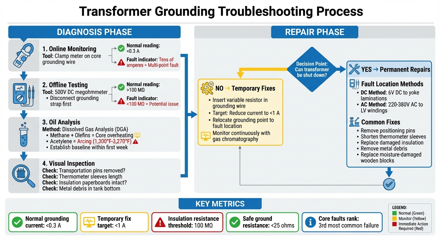
Diagnosing grounding issues requires the right tools and a methodical approach. A clamp meter is your go-to device for online monitoring. Simply clamp it around the core grounding wire while the transformer is operating to check the current flow. For healthy transformers, the reading should stay below 0.3 A. If you see currents in the range of tens of amperes, this signals a multi-point grounding fault that needs immediate attention. These readings help technicians quickly locate the problem area and start repairs.
For offline testing, disconnect the intentional grounding strap and use a 500V DC megohmmeter to measure the insulation resistance between the core and ground. If the reading is below 100 MΩ in service-aged transformers, it could indicate grounding issues. To narrow down the fault location, apply 220–380V AC to the low-voltage windings and use a milliampere meter. A zero reading from this test can help pinpoint the exact fault location.
Measuring Grounding Current
Routine checks with a clamp meter take just seconds and can provide a clear snapshot of the transformer's condition. If you notice elevated current levels, you can temporarily insert a variable resistor into the grounding wire to keep the current below 1 A until repairs can be made.
Using Oil Analysis for Diagnosis
Electrical measurements can be paired with chemical diagnostics for a more comprehensive assessment. Oil analysis can detect fault gases produced by degrading insulation materials. For example, high levels of methane and olefins, combined with stable levels of carbon monoxide and carbon dioxide, may indicate core overheating due to grounding problems. The presence of acetylene points to intermittent multi-point grounding, with arcing temperatures reaching between 1,300°F and 3,270°F.
"The DGA is the most informative method of detecting combustible gases. Although this is a laboratory method, it provides the earliest possible detection of any abnormal conditions in the transformer." – Your Electrical Guide
To stay ahead of potential problems, establish baseline Dissolved Gas Analysis (DGA) levels within the first week of operation and monitor for any sudden increases. Such changes should prompt immediate follow-up testing.
Inspecting Grounding Connections
After conducting electrical and chemical tests, visually inspect grounding connections for any overlooked issues. For instance, check if transportation positioning pins on the oil tank lid were removed or reversed during installation, as they can create unintended grounding paths. Look for excessively long thermometer sleeves or bushings on yoke bolts that might touch the core, and inspect the insulation paperboards between the core clamp and yoke for signs of damage or displacement.
In larger transformers with submersible pumps, electromagnetic forces can cause metal debris from worn pump bearings to accumulate and create a bridge between the core laminations and the tank. Draining a sample from the bottom of the tank and checking for metallic particles can help identify hidden faults.
How to Fix Transformer Grounding Problems
Once you've identified a grounding fault, the next step involves deciding between a temporary fix to maintain operations or scheduling a permanent repair during downtime. The urgency of the issue and the transformer's importance to your system will guide this choice. Below is a breakdown of corrective actions based on the diagnosis methods previously discussed.
Temporary Fixes for Active Faults
If shutting down the transformer immediately isn’t an option, you can implement temporary measures to manage circulating currents and keep them within safe limits. The aim is to reduce current flow to less than 1 A, as this prevents damage to the core and insulation. For reference, normal operating currents should remain below 0.3 A. If your clamp meter shows higher readings, consider these steps:
- Use a variable resistor: Insert it into the grounding wire and calculate the required resistance by dividing the measured voltage by 1 A.
- Relocate the grounding point: Move it to the fault location to shorten the current loop and minimize heat buildup.
During these temporary fixes, monitor the situation closely using gas chromatography. Pay attention to gas levels - methane and olefins indicate overheating in the core, while acetylene suggests intermittent arcing. Continuous diagnostics are essential to ensure these measures stabilize the fault until permanent repairs can be made.
Finding and Removing Multi-Point Faults
If temporary fixes don’t resolve the issue, you’ll need to address multi-point grounding faults permanently. This process involves taking the transformer offline and systematically removing unwanted grounding paths. Two common methods for locating faults include:
- Direct Current Method: Apply a 6V DC voltage to the yoke laminations and measure the voltage between lamination points. A zero or reverse reading will identify the fault.
- Alternating Current Method: Use a 220–380V AC supply on the low-voltage windings and check for zero current with a milliammeter to pinpoint the fault.
Look for typical causes of multi-point faults, such as improperly placed positioning pins, overly long thermometer sleeves, or yoke bolt bushings making contact with the core. Damaged insulation paperboards are another frequent issue. For transformers with submersible pumps, inspect the tank bottom for metal debris caused by worn bearings, as these particles can create conductive bridges under electromagnetic forces.
Permanent Repairs and Upgrades
Once the fault is located, take corrective actions to resolve the issue permanently. This may involve:
- Shortening components that are unintentionally making contact.
- Replacing damaged or compromised insulation materials.
- Removing any metallic debris from the oil tank.
If wooden blocks between clamps and yokes have absorbed moisture, replace them, as moisture can reduce insulation resistance to zero.
To prevent future issues, consider upgrading monitoring systems for metal and stainless-steel hoses to meet NEC, IEEE, or IEC standards. Also, confirm that all grounding conductors comply with these standards for proper sizing. This ensures they can safely handle fault currents and allow protective devices to trip as needed.
As Howard Williams, Technical Editor, emphasizes:
"Transformer grounding is not just a technical requirement but a cornerstone of power system safety and reliability".
How to Prevent Grounding Problems in Transformers
Preventing issues is always easier and cheaper than fixing them later. When it comes to transformers, proper installation and regular monitoring can stop grounding faults from turning into major failures. Core-related faults rank as the third most common transformer failure type, but with the right precautions, they’re largely avoidable. Tackling grounding problems starts with strong preventive measures and quick fault detection.
Installation Best Practices
Good prevention starts with how you install the transformer. One key step is to connect the transformer's neutral to the ground, which provides a stable voltage reference point. The core should have only one grounding point to avoid creating closed loops that might lead to circulating currents.
During installation, it’s crucial to ensure proper clearances between components. Core laminations, clamping plates, and yoke bolts should be spaced and insulated correctly to avoid unwanted contact. A common oversight is leaving positioning pins in place after transport. These pins must be removed - or reversed - during installation to avoid creating secondary grounding points that could cause issues.
When commissioning the transformer, use a clamp meter to check the current in the core grounding wire. A healthy transformer should measure below 0.3 A. Also, inspect thermometer sleeves and tank-cover accessories to ensure they don’t touch internal clamping structures or yoke edges. Before sealing the tank, remove any metallic debris that could create a conductive bridge between the core and the tank body. To establish a baseline for future monitoring, perform a gas chromatography oil analysis immediately after installation. This will help track methane and olefin levels over time.
Regular Maintenance and Monitoring
Once the transformer is installed, regular maintenance becomes essential. Periodically measure the current in the core grounding wire with a clamp meter. If the reading rises significantly above 0.3 A, it’s a sign of multi-point grounding, which needs immediate attention. Multi-point grounding can cause circulating currents to spike from minimal levels to tens of amperes, so early detection is critical.
Routine gas chromatography analysis of transformer oil is another key practice. Elevated methane and olefin levels indicate core overheating, while acetylene points to intermittent multi-point grounding. For transformers with submersible pumps, check the tank bottom for metal debris from worn bearings, as these particles can form conductive bridges. Additionally, test the insulation resistance of wooden blocks and paperboards between the clamp and yoke. Moisture or contamination can compromise insulation, creating unintended grounding paths.
Following Electrical Standards
Adhering to established electrical standards is vital for maintaining a reliable grounding system. In North America, NEC Article 250 outlines grounding and bonding requirements. For industrial and commercial systems, refer to IEEE Std. 142 (The Green Book), and use IEEE Std. 81 to verify ground resistance. Safe ground resistance values are typically less than 25 ohms.
For example, an industrial facility running a 13.8 kV substation faced damaging neutral overvoltages. Engineers reviewed the grounding diagram using IEEE Std. 142 and found an undersized earthing conductor. Upgrading to the correct size significantly reduced neutral voltages during faults, preventing relay misoperations and ensuring compliance with safety standards. This case highlights the importance of comparing your system against IEEE and NEC standards during the design phase. Doing so can help catch undersized conductors or missing return paths before they cause problems. By following these standards and maintaining proper installation and monitoring practices, you can ensure the long-term reliability of your transformer’s grounding system.
Conclusion: Maintaining Proper Transformer Grounding
Proper transformer grounding plays a critical role in ensuring safe and reliable power distribution. As William Conklin, Associate Editor at Electricity Forum, explains:
"Without proper earthing, ground faults may circulate unnoticed, creating long-term insulation stress and serious safety hazards."
Many grounding issues can be avoided by following a systematic approach.
Start with the basics: Bond the primary winding according to upstream supply rules, secure the transformer chassis to prevent the metal casing from becoming energized, and ground the secondary winding to provide a return path for downstream faults. David Peterson, Technical Author, highlights:
"It is critical that the metal case of the transformer be firmly bonded to ground, not just the primary wiring."
These steps form the foundation for effective grounding and ongoing safety.
After installation, maintenance becomes key. Use a clamp meter to monitor core grounding current - readings above 0.3 A may signal a fault. Regularly perform gas chromatography on transformer oil to catch early signs of overheating. Ground resistance should remain below 25 ohms, as outlined in IEEE Std. 81, and periodic testing can confirm this. Ensure grounding conductors are sized to handle maximum fault currents while keeping earth path impedance low. Document all earthing points and bonding configurations to simplify future maintenance.
Compliance with NEC Article 250 and IEEE Std. 142 is essential to protect both equipment and personnel. By focusing on proper installation, regular monitoring, and adherence to established standards, transformers can operate safely and efficiently for years.
For additional resources and high-quality electrical components to support your grounding needs, visit Electrical Trader (https://electricaltrader.com).
FAQs
How can I tell if my transformer uses single-point or multi-point grounding?
To figure out the grounding type of your transformer, take a close look at how its connections are set up.
- Single-point grounding means all systems are tied to a single main point, like a central electrical ground bar. This setup helps cut down on interference.
- Multi-point grounding, on the other hand, connects at several locations. While this can help reduce noise, it also alters the electrical properties.
If every ground connection leads back to one central spot, it's single-point grounding. If the connections are spread across multiple points, it's multi-point grounding.
What core grounding current level means I should shut the transformer down?
If a core grounding current points to a fault or abnormal condition, the transformer must be shut down immediately to prevent damage or safety hazards. Although thresholds can differ, detecting any unusual or significant core-ground current during testing or operation calls for an immediate shutdown to mitigate potential problems.
Which test should I run first: clamp meter, megohmmeter, or oil (DGA) analysis?
Start by using a clamp meter to quickly measure the current flow and spot any unusual electrical activity. After that, switch to a megohmmeter to test the insulation resistance, which can help pinpoint potential faults in the system. Lastly, conduct an oil analysis (DGA) to examine the transformer's internal condition, checking for issues like overheating or arcing. Following this sequence ensures a comprehensive and efficient evaluation of the transformer's overall health.