
Checklist for MIL-STD-704 Compliance Testing
If you test to MIL-STD-704, the job is simple to state: prove the unit can take aircraft power as delivered at its input terminals without damage or unsafe behavior.
I’d boil this article down to a short pre-test and test-day list: confirm the right MIL-STD-704 revision, pick the matching MIL-HDBK-704 method, define pass/fail for all 5 modes, and record clean data at the EUT terminals. The article also flags hard numbers you need up front, like 115/200 V AC at 400 Hz, 28 V or 270 V DC, 360 to 800 Hz for variable frequency, and 50 ms max for transfer gaps.
Here’s the fast version of what you need to check:
- Scope: MIL-STD-704 covers aircraft power characteristics, not EMI
- Documents: MIL-STD-704 revision, MIL-HDBK-704, ICDs, item specs, and related standards where needed
- Modes: Normal, Abnormal, Transfer, Emergency, and Starting
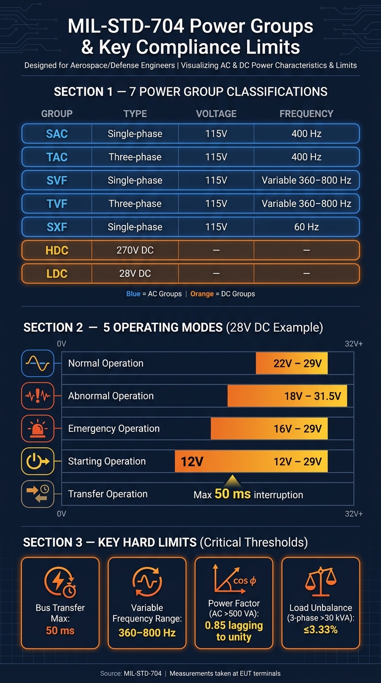
- Power groups: SAC, TAC, SVF, TVF, SXF, HDC, and LDC
- Setup checks: calibration, source range, wiring, grounding, polarity, and phase sequence
- Core limits: voltage, frequency, transfer time, power factor, and load balance where they apply
- Records: timestamps, waveforms, instrument status, anomaly log, and final compliance matrix
A few numbers stand out. For example, 28 VDC starting can drop to 12 V, variable-frequency AC can run from 360 to 800 Hz, and bus transfer interruption must stay at or below 50 milliseconds. Those values shape both the test plan and the pass/fail call.
| Area | What I’d confirm first |
|---|---|
| Standard basis | Correct MIL-STD-704 revision and matching handbook method |
| EUT definition | Part number, hardware rev, software/firmware version |
| Test coverage | All 5 modes mapped against each required condition |
| Lab readiness | Source capability, calibration traceability, data recording |
| Safety checks | Ground isolation, no chassis return, polarity and phase reversal checks |
| Final evidence | Measured data tied to requirement paragraphs |
If I were using this article as a guide, I’d treat it as a clean roadmap: lock the test matrix first, run nominal conditions before abnormal ones, and make sure every result ties back to a requirement paragraph.
MIL-STD-704 Power Groups & Key Compliance Limits at a Glance
Avionics DO-160/MIL-STD-704 Tests Using Keysight AC6900 Series 3-Phase AC Source & PathWave Software
sbb-itb-501186b
Pre-Test Planning Checklist
Once the revision and required documents are confirmed, lock the test plan before any power is applied. Put every setup detail, every pass/fail rule, and every lab-readiness check in writing before any power reaches the equipment under test (EUT).
Confirm the Equipment Under Test, Operating Modes, and Pass/Fail Criteria
Document the EUT’s part number, hardware revision, and software/firmware version. Then verify all five operating modes: Normal, Abnormal, Transfer, Emergency, and Starting.
Each mode needs its own pass/fail definition before testing begins. That matters because a unit can behave one way in Normal mode and very differently during Transfer or Starting.
"The test requirements for the utilization equipment shall be in accordance with the equipment's detail specification." - Viable Power
Write down the accepted response for each condition ahead of time. That gives the test team a clear standard and makes later review much less subjective.
Verify Lab Capability, Instrumentation, and Calibration Traceability
After the EUT and operating modes are set, confirm that the lab can produce the required power conditions. The seven power group classifications below determine which MIL-HDBK-704 test methods apply:
| Power Group | Description |
|---|---|
| SAC | Single-phase 115V / 400 Hz |
| TAC | Three-phase 115V / 400 Hz |
| SVF | Single-phase 115V variable frequency |
| TVF | Three-phase 115V variable frequency |
| SXF | Single-phase 115V / 60 Hz |
| HDC | 270V DC |
| LDC | 28V DC |
For variable frequency systems, the source must cover 360 to 800 Hz. For bus transfer simulations, the setup must keep the transfer gap to no more than 50 milliseconds.
Also confirm calibration status and recording capability for:
- Oscilloscopes
- Power analyzers
- Data loggers
Those checks need to be traceable and current.
Lock Down Configuration, Safety Controls, and Support Hardware
Record every piece of support hardware used in the setup so the test configuration can be repeated later. If someone needs to rerun the setup months from now, that record is what keeps the process consistent.
Protective devices must operate independently of the control and regulation equipment.
Before power-up, verify these physical checks:
- All electrical power input terminals are isolated from the case ground
- The chassis is not being used as a power return
- DC polarity-reversal protection is checked before power-up
- AC phase-reversal protection is checked before power-up
These are simple checks on paper, but they can prevent a bad test day fast.
Input Power Condition Checklist
Use the approved test matrix to check each required power condition in order. Start with nominal power. Then move to abnormal and transfer conditions.
Check Steady-State Voltage, Frequency, and Normal Operation Limits
Use these nominal values for the power system in scope.
| Power System Type | Nominal Voltage | Nominal Frequency | Allowable Frequency Range |
|---|---|---|---|
| Standard AC | 115/200 V | 400 Hz | N/A |
| Variable Frequency AC | 115/200 V | N/A | 360–800 Hz |
| Double-Voltage AC | 230/400 V | 400 Hz | N/A |
| Single-Phase AC | 115 V | 60 Hz | N/A |
| 28V DC | 28 V | N/A | N/A |
| 270V DC | 270 V | N/A | N/A |
Source: MIL-STD-704 General Requirements
Take measurements at the EUT terminals. For 115 V AC, the reading must stay within 113–118 V. For 28 VDC, keep it within 24–29 V. For 270 VDC, keep it within 260–280 V.
Next, confirm the power-system setup. AC uses grounded-neutral single-phase or three-phase A-B-C sequencing. DC uses a two-wire or negative-ground return.
For AC loads above 500 VA, check that power factor stays between 0.85 lagging and unity at 50% load or higher. Where three-phase power is required, use a balanced three-phase source.
Check nominal limits first. Treat that setup as the baseline for every later test. After nominal conditions pass, run the abnormal events without changing the setup.
Apply Transients and Abnormal Power Events
After steady-state checks are done, move to abnormal conditions.
For 28 VDC systems, test both electric starting and emergency operation. Electric starting allows 12–29 V. Emergency operation allows 16–29 V. The equipment must remain functional in both ranges.
For three-phase AC systems, test phase reversal. If the A-B-C sequence is reversed, the EUT must not be damaged. If equipment is above 30 kVA, also verify load unbalance stays at 3.33% or less of the total three-phase load.
During bus transfer, keep voltage and frequency interruption below 50 ms. For DC equipment, also check that reversing the positive and negative connections does not cause damage.
Test All Critical Operating Modes Under Each Required Condition
Track every condition against every operating mode so nothing slips through the cracks. Apply each required condition across Normal, Abnormal, Transfer, Emergency, and Starting modes.
Before testing starts, build a cross-reference matrix. Use modes as rows and conditions as columns. Mark each cell as:
- Tested
- Not applicable
- Pending
Use that matrix as the evidence map for the final compliance report.
Give extra attention to Starting mode on 28 VDC systems. During electric starting, voltage can fall to 12 V, so the equipment must stay functional at that lower threshold.
Test Execution and Documentation Checklist
Results don't hold up without complete records. If timestamps, waveform files, or calibration references are missing, traceability can fall apart.
Use a Written Procedure and Verify Instrument Setup Before Each Sequence
After the matrix is approved, run each condition in order and log it against the procedure. Each test sequence should follow a written procedure based on MIL-HDBK-704 and be cross-referenced to the right MIL-STD-704 paragraphs, such as Section 5.2 for AC characteristics or Section 5.3 for DC characteristics.
Before every run, confirm that the source settings, sampling, trigger, EUT mode, and fixture wiring match the approved procedure. It sounds basic, but this is where small setup mistakes turn into bad data.
Record Data with Timestamps, Waveforms, and Clear Traceability
Once the setup checks out, record the results right away. Capture applied voltage, current, frequency, phase sequence where it applies, and equipment response at every step. Save waveform files and screenshots so each result links back to a specific condition and setup. Record each result against the approved test matrix. Log anomalies right away with a reference number.
You also need to account for external power source voltage drops: up to 5 V for AC, 2 V for 28 V DC, and 10 V for 270 V DC.
Include Test Tables for Conditions, Instruments, and Results
Use three tables: conditions, instruments, and results.
MIL-STD-704 Power Conditions and Applied Limits (28 V DC Example)
| Power Condition | Applied Limits | Requirement Paragraph |
|---|---|---|
| Normal Operation | 22 V to 29 V | 5.3 |
| Abnormal Operation | 18 V to 31.5 V | 5.3 |
| Emergency Operation | 16 V to 29 V | 5.3 |
| Starting Operation | 12 V to 29 V | 5.3 |
| Transfer Operation | Max 50 ms interruption | 5.1 |
Required Instruments and Calibration Status
| Instrument | Measured Parameters | Calibration Status |
|---|---|---|
| Programmable AC/DC Power Source | Voltage, Frequency, Current, Phase Angle | |
| Waveform Generator | Transient Profiles, Harmonic Distortion | |
| Linear Power Amplifier | Slew Rate, Bandwidth, Peak Power | |
| Digital Oscilloscope | Waveform Capture, Timestamps |
Test Condition Summary
| Test Condition | Measured Response | Pass/Fail | Anomaly Ref. |
|---|---|---|---|
Log every deviation, even minor ones. The completed tables become the evidence set for the compliance matrix.
Post-Test Review and Conclusion
Compare Results to Requirements and Document Any Nonconformances
Use the completed test matrix to close out each requirement against the measured data. Once testing is done, compare every result with the limits for the applicable MIL-STD-704 power category. Then check that testing covered all required operating modes. Before the final report goes out, review each measured condition against the approved test matrix.
Also confirm that power loss or AC phase loss did not cause damage or unsafe behavior. Do the same for load unbalance, power-factor deviation, and input reversal, where those checks apply.
If a result fails or lands in a gray area, write it down clearly. Include:
- The operating mode
- The power condition applied
- The measured value
- The probable cause
That gives engineering a clean handoff for follow-up work.
Build the Compliance Matrix and Final Test Report
The final report must include the test objective, MIL-STD-704 revision, EUT configuration, setup diagram, procedure, calibration records, waveform plots, deviation log, and conclusion. Each result should link to the matching requirement paragraph.
Use this matrix to turn raw test data into a clear pass/fail record:
| MIL-STD-704 Requirement | Test Step | Measured Result | Status |
|---|---|---|---|
| Normal steady-state voltage for the applicable system category | |||
| Emergency operation voltage for the applicable system category | |||
| Transfer characteristics stayed within normal limits for no more than 50 ms during bus or source transfers | |||
| Load unbalance stayed within limits for three-phase AC equipment exceeding 30 kVA | |||
| Power factor stayed between 0.85 lagging and unity for AC equipment greater than 500 VA | |||
| Input terminals remained isolated from case ground | |||
| Equipment was not damaged by line/neutral, phase sequence, or positive/negative reversal as applicable |
"Test method MIL-HDBK-704 should be used to determine that the utilization equipment complies with this standard." - MIL-STD-704
Key Points to Carry Into Future Test Campaigns
Close out every anomaly before issuing the final report. Include all traceability records so each result links back to a requirement paragraph.
FAQs
How do I know which MIL-STD-704 revision applies?
Check your project or procurement documents first. If they name a specific revision, use that version.
If they don’t list one, use the most recent active revision: MIL-STD-704F.
You can also confirm the current status and any supersession details through official Department of Defense standards sources, such as the ASSIST database.
What’s the difference between MIL-STD-704 and MIL-HDBK-704?
MIL-STD-704 sets the electrical power rules for aircraft power systems. It covers the main AC and DC power parameters and defines how that power should behave on the aircraft.
MIL-HDBK-704 is the companion handbook. It explains the test procedures used to show that utilization equipment complies with the MIL-STD-704 power characteristics.
What can cause a MIL-STD-704 compliance test to fail?
A MIL-STD-704 compliance test can fail when the aircraft electrical system moves outside the standard’s limits for voltage, frequency, or overall power quality.
The usual trouble spots are pretty clear: voltage spikes, under-voltage, over-voltage, phase unbalance, and the wrong power-source setup.
Tests can also fail when the system has too much load unbalance, or when pulsed and non-linear loads create voltage modulation or current distortion. On top of that, problems show up when equipment can’t deal with transient conditions, abnormal conditions, grounding, filtering, or surge-protection requirements.


