
5 Key Components of Hydrogen Fuel Cell Systems
Hydrogen fuel cells generate electricity by combining hydrogen and oxygen, producing only water and heat as byproducts. They achieve high efficiency by converting chemical energy directly into electrical energy without combustion. This article explains the five main components that make these systems work:
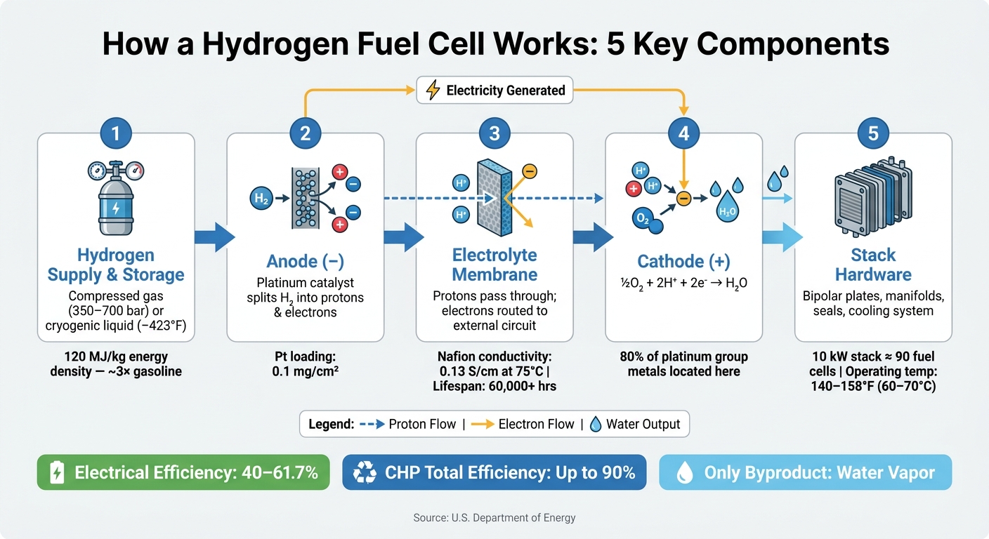
- Hydrogen Supply & Storage: Hydrogen is stored as compressed gas or cryogenic liquid. Compressed storage is more common for vehicles, but liquid storage offers higher energy density despite energy losses during liquefaction.
- Anode: The starting point of the reaction, where hydrogen is split into protons and electrons using a platinum catalyst.
- Electrolyte Membrane: Allows protons to pass through while blocking electrons, ensuring electricity generation via an external circuit.
- Cathode: Combines protons, electrons, and oxygen to form water, completing the reaction.
- Stack Hardware: Provides structural support, manages gas flow, and collects electrical current.
Each component is critical for efficient operation, with challenges like hydrogen purity, catalyst sensitivity, and water management impacting overall performance. Hydrogen fuel cells are a clean energy option, particularly for industries like transportation and manufacturing.
How a Hydrogen Fuel Cell Works: 5 Key Components Explained
How Hydrogen Fuel Cells Actually Work - Full System Breakdown
sbb-itb-501186b
1. Hydrogen Supply and Storage
The way hydrogen is stored plays a huge role in determining a fuel cell's range, weight, and overall usability.
There are two main storage methods: compressed gas storage and cryogenic liquid storage. Compressed gas storage is the go-to choice for most fuel cell electric vehicles (FCEVs). This method involves pressurizing hydrogen into lightweight, advanced Type IV tanks at either 5,000 psi (350 bar) or 10,000 psi (700 bar). To cover a driving range of over 300 miles, light-duty FCEVs typically need between 5 and 13 kilograms of hydrogen on board.
Cryogenic liquid storage, on the other hand, involves cooling hydrogen to an ultra-cold –423°F (–252.8°C) to make it a liquid. This method offers a higher energy density per volume. However, there’s a trade-off: turning hydrogen into a liquid consumes 30% to 40% of its total energy content, and the tanks must be heavily insulated to prevent evaporation or "boil-off".
Hydrogen is impressive when you look at energy per unit mass - it carries nearly three times the energy of gasoline (120 MJ/kg vs. 44 MJ/kg). But here’s the catch: on a volume basis, liquid hydrogen only delivers about 8 MJ/L, which is far less than gasoline's 32 MJ/L. This gap underscores the importance of advanced storage designs to fit enough hydrogen into a compact space without adding unnecessary weight.
"Hydrogen has the highest energy per mass of any fuel; however, its low ambient temperature density results in a low energy per unit volume, therefore requiring the development of advanced storage methods." - Department of Energy
Cost is another major challenge. Right now, a 700 bar Type IV tank costs roughly $15/kWh ($500/kg H₂), even at high production volumes. The U.S. Department of Energy has set a target to bring this down to $8/kWh ($266/kg H₂), which is a top priority for the industry.
Once hydrogen is securely stored, the next step in the process is the anode, where the fuel cell reaction begins.
2. Anode
The anode is where the hydrogen oxidation reaction kicks off in a fuel cell. Hydrogen gas is delivered through channels to the catalyst layer, where the process of conversion begins.
At this stage, the platinum (Pt) catalyst plays a key role by splitting hydrogen (H₂) into two protons (H⁺) and two electrons (e⁻). The reaction can be summarized as: H₂ → 2H⁺ + 2e⁻. Platinum makes this process possible by lowering the energy needed to break the hydrogen bonds, all while remaining unchanged itself.
"On the anode side, the platinum catalyst enables hydrogen molecules to be split into protons and electrons." - U.S. Department of Energy
Once separated, the protons move through the electrolyte membrane toward the cathode. Meanwhile, the electrons are directed through an external circuit, creating the electrical current that powers devices. This charge separation is the foundation of every hydrogen fuel cell.
Platinum's efficiency comes from its unique bonding properties, as explained by the Sabatier Principle. It holds hydrogen molecules just tightly enough to enable splitting but releases the resulting protons quickly enough to keep the process efficient. Impressively, even a small platinum loading - just 0.1 mg/cm² - is sufficient to maintain performance at the anode.
However, platinum has its challenges. It’s highly sensitive to impurities like carbon monoxide (CO). Even tiny amounts of CO can stick to the platinum surface, blocking its active sites - a problem known as catalyst poisoning. This sensitivity highlights the need for extremely pure hydrogen before it reaches the anode.
This effective charge separation at the anode sets the stage for the electrolyte membrane to guide the protons to their next destination: the cathode.
3. Electrolyte Membrane
After the anode splits hydrogen into protons and electrons, the electrolyte membrane steps in to do its job. Its main function is to let protons pass through while blocking electrons. This forces the electrons to travel through an external circuit, generating electricity in the process. The membrane also acts as a barrier, keeping hydrogen and oxygen gases apart to avoid direct mixing, which could cause a short circuit - or worse, combustion.
"The proton exchange membrane allows protons to pass through to reach the cathode catalyst layer while electrons are transferred to the cathode via an external circuit." - Dharmjeet Madhav, Researcher, KU Leuven
The most common material used for this membrane is Nafion, a polymer created by DuPont. Nafion has a unique structure with a hydrophobic backbone and hydrophilic sulfonic acid side chains, giving it a proton conductivity of 0.13 S/cm at 75°C (167°F) under full humidity. It’s also durable, lasting over 60,000 hours. However, its performance hinges on careful water management. Too little water increases electrical resistance, while too much water can flood the system, blocking gas flow to the catalyst.
For situations where managing water is more challenging, high-temperature membranes made from polybenzimidazole (PBI) provide a solid alternative. These membranes rely on phosphoric acid for proton transport and can handle temperatures as high as 220°C (428°F). They’re also better at dealing with impurities, tolerating carbon monoxide (CO) levels up to 3%, while Nafion requires hydrogen to be nearly pure.
| Feature | Nafion (PFSA) | Polybenzimidazole (PBI) |
|---|---|---|
| Operating Temp | 122°F–212°F (50°C–100°C) | 248°F–428°F (120°C–220°C) |
| Proton Conduction Medium | Liquid Water | Phosphoric Acid |
| Water Management | Critical | Not required |
| CO Tolerance | Very low | Up to 3% |
One challenge with traditional fluorinated membranes like Nafion is their reliance on PFAS (per- and polyfluoroalkyl substances). These "forever chemicals" persist in the environment, raising concerns about their long-term impact. To address this, researchers are exploring fluorine-free alternatives like SPX3, which aim to match Nafion’s conductivity without the associated toxicity risks.
4. Cathode
The cathode plays a crucial role in completing the reaction within a fuel cell. Here, protons from the electrolyte membrane and electrons from the external circuit combine with oxygen (O₂) through the half-cell reaction: ½ O₂ + 2H⁺ + 2e⁻ → H₂O.
This reaction takes place at the triple phase boundary (TPB) - a tiny zone where the catalyst, the electrolyte, and oxygen converge. A platinum catalyst, which accounts for nearly 80% of the cell's platinum group metal (PGM) content, is used to break the strong bonds in O₂. This high percentage of platinum is necessary because the oxygen reduction reaction (ORR) is relatively slow.
Since the ORR is exothermic, it generates both heat and water. To protect the membrane and sustain efficiency, cooling the cathode - using either water or air - is essential. Typically, fuel cells operate with an energy efficiency of 40% to 60%. However, when waste heat is captured in cogeneration systems, the overall efficiency can rise to as much as 85%.
One challenge at the cathode is flooding, which can block oxygen from reaching the catalyst and reduce performance. Toyota addressed this in its 2014 Mirai by using a 3D fine mesh flow field design. This design improved convective flow, ensuring efficient oxygen delivery and water removal without needing an additional humidifier.
5. Stack Hardware
Stack hardware provides the essential structure for fuel cell operation, supporting the electrochemical reactions occurring at the anode, membrane, and cathode. At the heart of this system are bipolar plates, which guide the flow of reactants and collect electrical current.
Bipolar plates are the foundation of the stack. Dr. Conor O'Brien of IDTechEx explains their importance:
"Bipolar plates (BPPs) serve as the structural backbone of a fuel cell, providing mechanical support, separating hydrogen and oxygen gases, and collecting the electrical current generated during operation."
These plates feature flow field patterns that direct hydrogen and oxygen across the membrane. The design of these patterns plays a key role in water management. Poorly designed plates can lead to flooding, where excess water blocks gas pores, or drying out, which can degrade performance. Materials commonly used for these plates include graphite, metal, and graphite-reinforced composite laminates. Graphite offers excellent corrosion resistance but tends to be heavier, while metal plates are thinner, allowing for higher power density, though they require protective coatings to withstand the acidic stack environment.
In addition to structural support, maintaining the right temperature is critical for efficient operation. Liquid-cooled stacks typically operate best between 140°F and 158°F (60°C and 70°C). To achieve this, the system uses a radiator, a water pump, and an ion exchange unit, which ensures the coolant maintains low electrical conductivity - an essential safety measure for high-voltage stacks. A 10 kW liquid-cooled stack, which includes about 90 fuel cells, along with its radiator and DC converter, can weigh around 530 lbs (240 kg).
Other key components include manifolds, gaskets, seals, and wiring harnesses. Manifolds ensure even distribution of reactants and coolant, reducing the risk of hot spots and wear. Gaskets and seals prevent leaks and keep hydrogen and oxygen separated. Meanwhile, high- and low-voltage wiring harnesses connect the stack to the power distribution unit and controller. Together, these elements determine the system's reliability and longevity.
Comparison Table
Each component plays a specific role in determining how the system operates and what happens when something goes wrong.
The table below summarizes the location, primary function, and potential failure impact of each key component:
| Component | Location | Primary Function | Impact of Failure |
|---|---|---|---|
| Hydrogen Supply & Storage | External to the stack (Balance of Plant) | Stores and regulates H₂ delivery to the anode | System fails to start; no power output; potential safety hazards |
| Anode | One side of the MEA (negative electrode) | Splits H₂ into protons and electrons via platinum catalyst | Gas channel blockage; sharp voltage drop; lower efficiency |
| Electrolyte Membrane | Center of the MEA, between electrodes | Conducts protons; prevents electrons and gas crossover | Internal short circuits; gas crossover; total system failure |
| Cathode | Opposite side of the MEA (positive electrode) | Combines protons, electrons, and O₂ to produce water | Catalyst degradation; oxygen blockage; power loss |
| Stack Hardware | Surrounding and between MEAs | Provides structure, gas channels, and electrical connections | Gas leakage; uneven heat distribution; increased electrical resistance |
The anode, electrolyte membrane, and cathode are compactly arranged within the Membrane Electrode Assembly (MEA), which functions as a single, sandwich-like unit. Surrounding this is the stack hardware, which ensures structural integrity and keeps gases properly separated. Meanwhile, the hydrogen supply system operates entirely outside the stack, delivering hydrogen to the anode.
A damaged electrolyte membrane can lead to hydrogen and oxygen crossover, which not only reduces efficiency but also creates safety concerns. Additionally, poor water management at the cathode may lead to water backing up into the membrane and anode, causing a chain reaction of issues across multiple components.
As highlighted by the U.S. Department of Energy:
"The polymer electrolyte membrane, or PEM... is the key to the fuel cell technology; it must permit only the necessary ions to pass between the anode and cathode."
This interdependence between components makes hydrogen fuel cell systems both intricate and challenging. Even a single failure can disrupt efficiency, potentially reducing it by as much as 61.7%.
Conclusion
The five key components of a hydrogen fuel cell - hydrogen supply and storage, anode, electrolyte membrane, cathode, and stack hardware - each serve a specific purpose in the system. Here's how it all works: hydrogen enters the anode, where it splits into protons and electrons. The electrolyte membrane allows only protons to pass through, while electrons are routed through an external circuit, generating electricity. At the cathode, the protons and electrons reunite to form water and release heat. Meanwhile, the stack hardware ensures the system operates smoothly by keeping gases separate and connecting cells in series to produce a useful voltage. This seamless integration drives the system's efficiency.
What sets hydrogen fuel cells apart is their ability to directly convert chemical energy into electricity, bypassing the inefficiencies of combustion and mechanical processes. Proton exchange membrane (PEM) fuel cells can reach electrical efficiencies as high as 61.7%, and combined heat and power (CHP) setups can push total efficiency to an impressive 90%.
Even more compelling is the environmental impact - or lack thereof. The only byproduct is water vapor. This makes hydrogen fuel cells a promising option for industries where batteries fall short, such as heavy-duty trucking, shipping, and industrial manufacturing. Looking ahead, hydrogen is expected to meet 18% of global energy needs by 2050, potentially cutting CO₂ emissions by 6 billion tons during that time.
Jichao Li of Jining University's Department of Mechanical Engineering emphasizes this potential:
"Hydrogen... will become an important alternative energy source and can form another pillar of the renewable electricity energy transition by replacing coal, oil, natural gas, and traditional hydrogen in different economic sectors."
Understanding the function of each component is essential for optimizing the use and upkeep of hydrogen fuel cell systems.
FAQs
Why is hydrogen storage so hard for vehicles?
Hydrogen storage presents a significant challenge because of its low energy density under normal conditions. To achieve a driving range of over 300 miles, vehicles typically require between 5–10 kg of hydrogen. This necessitates either high-pressure tanks (capable of holding up to 10,000 psi) or cryogenic storage at extremely low temperatures (-253 °C). Both methods come with trade-offs: they add complexity to the system, increase costs, and introduce potential safety concerns. At present, no single storage technology successfully balances the demands of affordability, safety, weight, and compactness.
What causes fuel cell catalysts to become 'poisoned'?
Fuel cell catalysts can lose their effectiveness when impurities attach to their active surface sites, disrupting critical electrochemical reactions. Some common culprits include carbon monoxide (CO), sulfurous gases, ammonia, and chloride ions. In high-temperature fuel cells, phosphoric acid that leaches out can also stick to the catalyst surface. This blockage hampers the catalyst's ability to facilitate reactions, ultimately lowering the power output.
How do fuel cells prevent membrane flooding or drying out?
Fuel cells rely on effective water management to maintain the right moisture balance. Externally, they control the pressure, temperature, and humidity of reactant gases, often employing a humidification system to hydrate the incoming air. Internally, carefully designed materials, flow channels, and membranes work together to ensure efficient water movement. To prevent excess moisture from disrupting the system, condensers and separators are used to remove surplus water, keeping the system's water levels just right.


