How to Identify Transformer Failure Modes Early
Transformers are critical to power distribution, but failures can cause costly outages. Early detection of issues like insulation breakdown, overheating, or mechanical stress can save millions. Here's how to spot problems before they escalate:
- Common Failure Modes: Electrical (insulation breakdown), mechanical (winding deformation), and thermal (overheating).
- Warning Signs: Oil leaks, bulging panels, unusual noises, burnt smells, or temperature spikes.
- Key Monitoring Tools: Dissolved Gas Analysis (DGA), thermal imaging, and electrical testing.
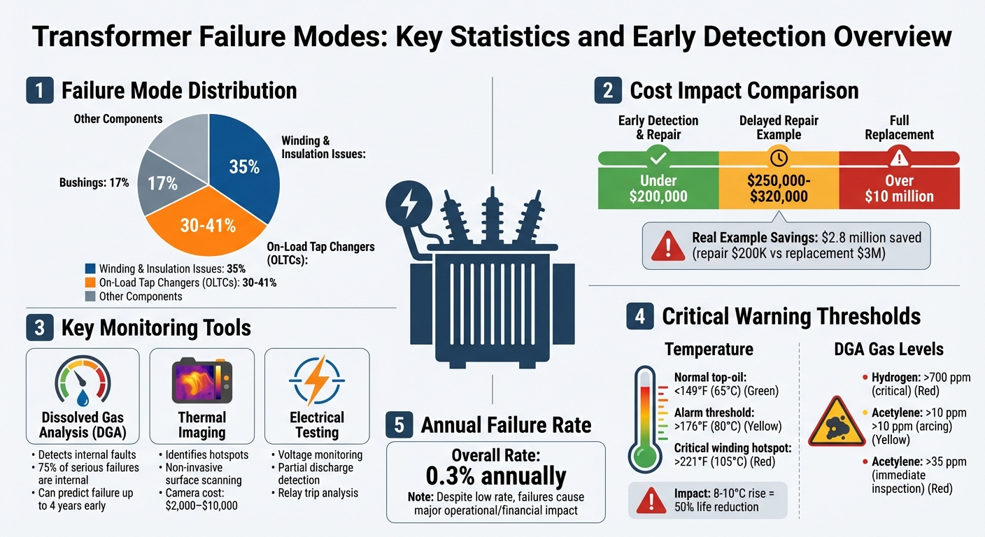
- Statistics: Winding and insulation issues cause ~35% of failures; On-Load Tap Changers (OLTCs) contribute 30-41%.
- Cost Impact: Repairs identified early can cost under $200,000, while replacements may exceed $10 million.
Proactive monitoring, regular inspections, and diagnostic tests like DGA and thermography are essential to maintaining transformer health and avoiding major failures.
Transformer Failure Modes: Statistics, Costs, and Early Detection Methods
Common Transformer Problems and Troubleshooting Tips
sbb-itb-501186b
Visual and Audible Warning Signs
Our senses often offer the first hints of trouble in transformers. Failures typically announce themselves through sight, sound, or even smell.
Visual Indicators
Oil leaks are a common red flag. Look for damp gaskets, stains on the tank, or puddles under the transformer - these are signs that seals are wearing out or corrosion is taking hold. Bubbling oil in the conservator is another clue, often pointing to internal gassing.
Physical changes in the transformer's structure can also signal problems. Bulging panels or tank covers might mean internal pressure is building up from gas or mechanical stress. Cracked or discolored bushings, surface tracking, and soot or burn marks often indicate arcing or insulation failure. Similarly, discolored paint, smoke, or even steam could be signs of overheating or internal arcing.
For example, during a 2012 thermography inspection of a 3,000 kVA transformer, a casing hotspot over 212°F (100°C) revealed internal arcing. Repairs costing about $70,000 prevented what could have been a $250,000 failure. Monthly visual checks - or inspections after severe weather or seismic events - are essential. Document findings with photos and thermal scans to monitor changes over time. These visual clues are invaluable for catching problems early and planning maintenance before issues escalate.
Audible Indicators
Transformers typically produce a steady, low-frequency hum caused by magnetostriction (50–60 cycles per second). But if that hum shifts to a harsh buzzing, it could mean core saturation, unbalanced loads, or displaced windings. Rattling or uneven buzzing often points to loose bolts or core clamps. Crackling, popping, or sizzling sounds suggest partial discharge, moisture in the insulation, or the corona effect. A high-pitched whining noise might indicate resonance in the windings or issues with the tap changer. A sudden "bang", on the other hand, could mean a short circuit, arc flash, or even a tank rupture.
"A failing transformer speaks - the key is knowing how to listen." - Taishan Transformer
Acoustic sensors or directional microphones can help pinpoint the source of unusual sounds. Any changes in the transformer's "acoustic signature" should be logged immediately, as these shifts are often the earliest signs of core or electrical problems. Recognizing these sound patterns early can lead to timely repairs and prevent larger issues.
Odors and Other Sensory Alerts
Smells can also reveal transformer issues. A sharp, acrid odor often signals insulation breakdown within the windings. The smell of burnt oil usually points to severe overheating or internal arcing, which breaks down the dielectric fluid. Strong chemical odors might indicate electrical stress and insulation failure.
If you notice smoke, visible flashing, or strong burnt odors, it’s critical to isolate the power or reduce the load immediately to avoid a catastrophic failure. When you detect a burnt smell but no visible smoke, infrared thermography can help confirm the presence of hot spots. Routine walk-throughs should train personnel to differentiate between normal heat and the distinct smell of degrading insulation.
"Odor is often the clearest sensory sign of a transformer fault." - Taishan Transformer
A surface that feels unusually hot or radiators that are excessively warm can confirm that a burnt odor is linked to internal overheating. Often, faults progress through subtle changes - starting with unusual sounds, followed by detectable odors, and finally visible signs like smoke or a tripped relay. These sensory observations, when combined with electrical and thermal testing, provide a comprehensive approach to early fault detection.
Electrical and Thermal Failure Indicators
Visual, audible, and odor cues might give you a heads-up about potential issues, but when it comes to pinpointing problems early, electrical and thermal measurements are the real game-changers. These indicators often highlight faults long before they become apparent in other ways.
Electrical Indicators
Voltage inconsistencies are one of the first signs of trouble. Problems like voltage sags, imbalances greater than 2% between phases, or flickering can point to insulation wear, changes in load configurations, or core and winding issues.
Protective relay trips are another critical sign. For example, differential protection activations could indicate internal winding faults, while a Buchholz relay trip might mean gas is building up due to internal arcing. Other signs, like blown high-voltage fuses or unusual phase readings - such as one phase showing zero while the others are abnormally high or low - shouldn't be ignored.
Partial discharge (PD) is another red flag. Caused by insulation voids, contamination, or defects, PD leads to localized damage that can grow into a major failure. Tools like UHF sensors or ultrasonic scanners can detect PD during routine checks, especially in high-voltage equipment. Reviewing logs from protection devices, such as differential, Buchholz, and overcurrent relays, can also help spot emerging issues before they escalate.
Thermal measurements, on the other hand, provide a different but equally important perspective, revealing internal conditions that aren't visible to the naked eye.
Thermal Indicators
Thermal imaging is a go-to method for diagnosing problems. Hotspots on transformer tanks, bushings, or cable terminals often mean loose connections, high contact resistance, or internal arcing. If these hotspots exceed alarm thresholds, they could signal serious issues like poor oil circulation or internal arcing, requiring immediate attention.
Top-oil temperature is another critical metric. If it rises during load conditions, it might indicate cooling issues like clogged radiators or malfunctioning pumps. Ideally, top-oil temperatures should stay under 149°F (65°C), with anything above 176°F (80°C) posing a significant risk. Winding hotspot temperatures are another key factor - normal values are below 185°F (85°C), but readings over 221°F (105°C) are considered critical. For bushings, surface temperatures should generally remain within 27°F (15°C) of the ambient temperature, with a rise of more than 54°F (30°C) signaling trouble.
"A temperature rise of 8-10 degrees Celsius beyond the maximum working value (if sustained) can halve the life of the transformer!" - Saira Dar, Level III Thermographer, 3i Condition Monitoring Consultancy, LTD
Thermal imbalances across radiator fins are another warning sign. If one radiator is noticeably cooler than the others or cooling fans are running non-stop, it could indicate blocked oil circulation. Regular thermographic inspections, especially during peak loads or in high ambient temperatures, are essential for spotting these issues. Conducting a baseline thermal scan right after installation provides a reference point for future comparisons, making it easier to detect trends. Additionally, fiber optic sensors offer real-time monitoring of winding hotspots, unaffected by electromagnetic interference, making them a reliable alternative to traditional methods.
Main Transformer Failure Modes to Monitor
Transformers are complex systems, and understanding their key failure modes can help prevent costly outages. Data shows that winding and insulation issues are behind roughly 35% of major failures, while on-load tap changers (OLTCs) contribute between 30% to 41%.
Winding Failures
Winding failures are often caused by extreme mechanical and electrical stress. Short-circuit impulses generate high electromagnetic forces, which can deform conductors - leading to buckling, telescoping, or loosening. These forces increase exponentially with the current, so even brief fault events can leave lasting damage.
Electrical stress from lightning strikes, switching surges, or overvoltages can push insulation beyond its limits, causing turn-to-turn breakdowns or flashovers. Additionally, overloading and poor cooling accelerate the aging of cellulose insulation, making it brittle and prone to cracking. Weak manufacturing practices, like poor axial compression or faulty wire joints, can also lead to overheating during normal operation.
"Winding failures are the most common contributors to major transformer failures, and they account for most of them in terms of mechanical faults such as winding loosening and deformation." – Rugged Monitoring
To monitor winding health, tools like Frequency Response Analysis (FRA) can detect shifts after major events, while Dissolved Gas Analysis (DGA) identifies arcing through hydrogen and acetylene spikes. Routine insulation resistance tests are also helpful in spotting shorted turns. A real-world example from September 2025 illustrates this: a 500 MVA, 400 kV transformer in India was saved when DGA flagged rising acetylene and hydrogen levels. Infrared thermography confirmed a hotspot, and FRA detected winding displacement - saving over $8 million in replacement costs.
Bushing Failures
Bushings, which connect high-voltage windings to external circuits, are responsible for about 17% of transformer failures, with more than half resulting in catastrophic fires or explosions. Failures often stem from electrical stress, moisture ingress, or physical damage that compromises insulation.
Visual inspections and infrared scans can catch early signs like oil leaks, cracks, or carbon tracking, which indicate loose connections or hotspots. Electrical testing is equally critical - a capacitance shift above 5% from baseline signals internal insulation problems.
"Bushing degradation is a leading cause of catastrophic transformer failures." – Qualitrol Corp
A solid monitoring routine includes monthly visual checks, quarterly infrared scans, and annual electrical tests for capacitance and power factor. For older bushings (15–20 years or more), inspections should become more frequent to address accelerated insulation aging.
On-Load Tap Changer (OLTC) Failures
OLTCs regulate voltage while the transformer remains operational, but they are prone to wear and are linked to 30% to 41% of transformer failures. Common issues include contact erosion from arcing, mechanical wear, poor lubrication, and oil contamination.
Warning signs include voltage instability, flickering, or unusual clicking sounds during tap changes. Arcing in the diverter switch may cause carbon deposits and sludge, which show up as hotspots on infrared scans. Online DGA is invaluable here - acetylene levels above 35 ppm signal the need for immediate inspection.
For example, in July 2025, a 63 MVA, 132/33 kV transformer was saved when online DGA detected acetylene rising from 6 ppm to 43 ppm in just seven days. Infrared scans confirmed a hotspot near the OLTC compartment, enabling timely repairs that avoided over $250,000 in costs and weeks of downtime. To maintain OLTCs, detailed inspections every 25,000 operations or 3–5 years, along with oil filtration every 2–3 years, are recommended.
Insulation Degradation
Insulation degradation tends to progress slowly, often going unnoticed until failure occurs. Moisture ingress through faulty seals or breathers reduces dielectric strength and promotes partial discharge. Aging cellulose insulation becomes brittle and cracks over time, eventually leading to short circuits.
"The difference between a transformer that lasts 40 years and one that fails in 10 often comes down to the quality of seals and gaskets." – Giga Energy
DGA is a key tool for monitoring insulation health. Carbon monoxide (CO) indicates cellulose breakdown, while hydrogen points to partial discharge. Advanced techniques like Polarization-Depolarization Current (PDC) and Frequency Domain Spectroscopy (FDS) can detect early moisture issues that standard tests might miss. Regular oil sampling, paired with power factor testing, provides a reliable picture of insulation health before irreversible damage sets in.
Diagnostic Tests for Early Detection
Identifying transformer issues early can prevent costly failures. By using diagnostic tools like Dissolved Gas Analysis (DGA), thermal imaging, and other methods, potential problems can be spotted before they escalate.
Infrared thermography is a non-invasive way to detect surface temperature anomalies. It identifies localized hotspots, loose connections, and cooling system blockages without requiring equipment shutdowns. Even a consistent 14–18°F rise above the maximum rating can cut a transformer's lifespan in half. For instance, in 2012, Saira Dar used a FLIR T640 to scan a 3,000 kVA transformer and found a hotspot at 212°F - far exceeding the 176°F threshold. Immediate repairs costing $90,000 prevented a failure that could have cost over $320,000.
"The beauty of thermography is that it is so visual. I knew it would be hard for anybody to see those images and walk away from the situation." – Saira Dar, Level III Thermographer, 3i Condition Monitoring Consultancy, LTD
Dissolved Gas Analysis (DGA)
DGA stands out for its ability to predict transformer faults. It measures nine key gases - hydrogen (H₂), methane (CH₄), ethane (C₂H₆), ethylene (C₂H₄), acetylene (C₂H₂), carbon monoxide (CO), carbon dioxide (CO₂), nitrogen, and oxygen - produced when insulating materials break down. Each gas points to specific issues: acetylene indicates high-energy arcing, while carbon monoxide suggests cellulose insulation degradation. Internal faults, which DGA is designed to detect, are responsible for about 75% of serious transformer failures.
DGA results are interpreted using tools like the Duval Triangle, Rogers Ratios, and the Key Gas Method. The Duval Triangle, which analyzes methane, ethylene, and acetylene levels, classifies faults with 96% accuracy. However, since different methods can sometimes yield conflicting results, it's best to confirm findings with at least two techniques. A study of 700 cases found the Three Ratios Technique to be the most accurate at 99.21%, compared to 81.52% for the Duval Triangle and 48.91% for IEC ratios.
Critical gas thresholds include hydrogen levels above 700 ppm and acetylene levels exceeding 10 ppm. Beyond absolute levels, monitoring how quickly gas levels rise is crucial, as sharp increases often signal active problems. While DGA is typically done annually for standard transformers, critical units may require quarterly testing.
| Gas | Primary Fault Indication |
|---|---|
| Hydrogen (H₂) | Partial discharge, electrolysis of water, or severe arcing |
| Methane (CH₄) | Low-temperature thermal oil decomposition (<572°F) |
| Ethane (C₂H₆) | Medium-temperature thermal oil decomposition (572–1,292°F) |
| Ethylene (C₂H₄) | High-temperature thermal oil decomposition (>1,292°F) |
| Acetylene (C₂H₂) | High-energy electrical arcing |
| Carbon Monoxide (CO) | Cellulose insulation degradation |
| Carbon Dioxide (CO₂) | Overheating or normal aging of cellulose insulation |
Thermal Imaging and Hotspot Detection
Thermal imaging uses infrared cameras to identify temperature anomalies without physical contact. For accurate results, ensure proper camera settings, including emissivity, Reflected Apparent Temperature (RAT), and ambient temperature. Scans should be performed during peak load times to highlight issues under maximum stress.
Key areas to inspect include power cables, bushing connections, cooling radiators, and oil levels, which can be inferred from the tank’s thermal profile. Comparing temperatures across phases can reveal irregularities like high-resistance joints or internal faults. Cross-checking thermal images with physical temperature gauges can also identify sensor errors or localized hotspots missed by fixed sensors.
Thermal scans can uncover blocked cooling fins or malfunctioning fans and pumps, which may indicate deeper issues like arcing contacts or winding faults. Investing in an infrared camera, priced between $2,000 and $10,000, can avert failures that might otherwise cost over $150,000.
Other Diagnostic Methods
Other tests complement gas and thermal analyses for a more comprehensive approach. Sweep Frequency Response Analysis (SFRA) detects mechanical shifts in windings or core damage by analyzing electrical responses across frequencies. Performing SFRA upon installation establishes a baseline for future comparisons.
Oil quality testing evaluates the Dielectric Breakdown Voltage (BDV) for moisture and particulates, acidity levels for oxidation, and Interfacial Tension (IFT) for polar contaminants. A typical oil test costs $150–$300 and can prevent failures exceeding $150,000. Warning signs include dielectric strength below 30 kV, water content over 30 ppm, and acid numbers above 0.3 mg KOH/g.
Furan analysis measures cellulose insulation degradation by detecting furfural compounds in the oil. Furan levels above 1.0 ppm indicate severe insulation aging. Partial Discharge (PD) monitoring uses acoustic or UHF sensors to detect low-energy discharges before they escalate into arcing. Advanced methods like Polarization-Depolarization Current (PDC) and Frequency Domain Spectroscopy (FDS) can identify moisture issues that standard tests might miss.
"DGA is often expressed as the holy grail of electrical oil analysis... it can identify a potential failure of a transformer up to 4 years before it occurs." – Adam, Oil Analysis Lab Expert
Preventive Maintenance Strategies
A consistent maintenance routine is key to keeping transformers running smoothly for decades - sometimes exceeding 40 years. Regular checks and upkeep help identify and address potential problems before they escalate. Weekly visual inspections should focus on spotting oil leaks, bulging panels, cracked bushings, and any unusual sounds, which can signal loose windings or core issues.
Routine Monitoring and Inspections
After identifying early warning signs through diagnostic tests, regular visual and operational inspections help maintain transformer reliability. For example, check dehydrating breathers and replace silica gel once it shows saturation. During service interruptions, operate off-circuit tap changers to prevent contacts from sticking.
Annual DGA (Dissolved Gas Analysis) tests are essential, but for transformers rated above 10 MVA, quarterly testing is recommended. Use infrared thermography every 2–3 years under full load conditions to identify hotspots and ensure proper cooling. Keeping cooling systems clean and functional is critical to avoiding overheating. Additionally, always adhere to the nameplate loading limits, as consistent overloading is a primary cause of insulation failure.
"An increased operating temperature of only 8 to 10°C will reduce transformer life by one-half." – Manuel Bolotinha, Senior Consultant
Sourcing Reliable Replacement Parts
When replacing parts, use only UL-listed and ANSI/IEEE-compliant components. Ensure suppliers provide proper engineering oversight and transparent manufacturing processes. This guarantees compatibility with your transformer's voltage, K-factor, and cooling class. For quick access to quality transformers and parts, Electrical Trader (https://electricaltrader.com) is a reliable resource. If considering refurbished units, always request the DGA history to confirm there are no ongoing arcing or thermal issues.
Choosing dependable parts is just as important as regular maintenance, as both contribute to a solid long-term strategy.
Establishing a Long-Term Maintenance Plan
Detailed records of tests and inspections are invaluable for spotting trends and planning future maintenance. Small transformers (≤1 MVA) should undergo oil testing every 2–3 years, medium units (1–10 MVA) annually, and critical transformers (>10 MVA) biannually with quarterly DGA tests, adjusting based on operating conditions.
Budget for comprehensive overhauls every 8–10 years. After major events like short circuits, transport, or seismic activity, schedule electrical tests (such as insulation resistance, TTR, and winding resistance) and mechanical assessments like SFRA (Sweep Frequency Response Analysis). For continuous monitoring, consider IIoT sensors to track DGA levels, partial discharge, and hotspots in real time.
Conclusion
Catching problems early can stop small issues from turning into expensive disasters. While transformers are generally dependable, with an annual failure rate of just 0.3%, failures can still cause serious operational and financial setbacks. Most transformer breakdowns stem from key areas like windings, insulation, and OLTCs. The silver lining? Many issues develop gradually, offering warning signs if you know what to watch for.
These statistics highlight the importance of staying ahead with fault detection. Combining tools like visual inspections, dissolved gas analysis (DGA), thermal imaging, and electrical testing gives you a complete picture of your transformer's condition. Pay extra attention to components prone to failure, such as windings, bushings, and OLTCs. Even a small, sustained temperature rise of 8–10°C (14°F to 18°F) above design limits can slash your transformer's life expectancy by half.
Regular monitoring and timely maintenance are the cornerstones of transformer reliability. As mentioned in the diagnostic tests section, condition-based monitoring using real-time sensors is a game-changer. Shifting from a fixed schedule to condition-based monitoring allows you to spot problems early. Tools like real-time sensors and trend analysis can catch signs like increasing acetylene levels or emerging hotspots while they’re still manageable. For instance, a utility in South America saved $2.8 million by identifying a localized arcing fault through DGA before visible symptoms appeared. The repair cost less than $200,000, avoiding a potential $3 million replacement.
Investing in modern monitoring systems and regular testing pays off. And when it’s time to replace parts, working with dependable suppliers like Electrical Trader ensures you get high-quality components that meet industry standards. Pairing reliable parts with a strong maintenance plan, detailed records, and quick action on warning signs can help your transformers remain operational for decades. This proactive approach not only saves money but also ensures long-term reliability.
FAQs
What warning signs indicate a transformer should be shut down immediately?
Certain warning signs signal that a transformer requires immediate attention and shutdown to avoid severe consequences. These include:
- Unusual noises: If you hear abnormal humming or buzzing sounds, it could point to internal electrical or mechanical issues.
- Excessive vibrations: Transformers operating under normal conditions should not vibrate excessively. This could indicate internal damage or loose components.
- Overheating: Temperatures rising beyond acceptable levels suggest potential problems with cooling systems or internal faults.
- Visible issues: Look for oil leaks, discoloration, or other physical abnormalities. These might indicate insulation failure, structural damage, or other serious issues.
Addressing these problems quickly can help prevent further damage, costly repairs, or unexpected outages.
How do I choose the right DGA testing frequency for my transformer?
To determine how often to perform DGA testing, you’ll need to look at a few key factors: the transformer’s age, its working environment, and the likelihood of faults. For transformers in stable condition, annual testing usually does the job. However, if the transformer is older or under stress, you might want to test it every 3–6 months. For high-priority equipment, continuous monitoring systems can offer real-time insights. The goal is to tailor the testing schedule to the transformer's specific condition, helping you catch potential issues early and plan maintenance accordingly.
What’s the fastest way to confirm a suspected hotspot or internal arcing?
The fastest way to verify a suspected hotspot or internal arcing in a transformer is by using Electrical Signature Analysis (ESA). This non-intrusive technique relies on sensors like Current Transformers and Voltage Transformers to track real-time current, voltage, and harmonic patterns. ESA allows you to detect problems like hotspots or arcing without shutting down the transformer, making it possible to identify internal issues early on.