
Thermal Resistance Standards Explained
Thermal resistance standards help engineers manage heat in electronic components. These standards ensure components operate safely by providing consistent ways to measure and compare heat dissipation. Key points include:
- Thermal resistance (Rθ) measures how much a component resists heat flow, expressed in °C/W. Lower values mean better heat dissipation.
- JEDEC standards like JESD51-12 ensure manufacturers provide comparable thermal data.
- Datasheets often list metrics like RθJA (junction-to-ambient) and RθJC (junction-to-case) for design calculations.
- More accurate parameters, like Ψ (thermal characterization), account for multiple heat paths, improving real-world temperature estimates.
- PCB design (e.g., copper thickness, thermal vias) significantly affects thermal performance beyond datasheet values.
- Standards also cover thermal interface materials (TIMs), highlighting their role in reducing heat resistance.
Understanding these metrics and standards helps you design efficient, heat-safe systems.
Key Thermal Resistance Concepts
What Is Thermal Resistance?
Thermal resistance (R<sub>θ</sub>) is a measure of how much a material or component resists the flow of heat between two points. It works similarly to Ohm's Law but applies to heat transfer: ΔT = P × R<sub>θ</sub>, where ΔT is the temperature difference, P is the power dissipation, and R<sub>θ</sub> is the thermal resistance. A lower R<sub>θ</sub> indicates better heat flow efficiency.
The units for thermal resistance are °C/W or K/W, as one degree Celsius equals one Kelvin in this context. For example, an LM7805 in a TO-220 package has an R<sub>θJA</sub> of about 50°C/W. At 1.44 W of power dissipation, the junction temperature will rise approximately 72°C (around 130°F) above the ambient temperature unless a heatsink is used.
This concept is fundamental to understanding other thermal parameters used in electronics.
Thermal Resistance vs. Related Thermal Metrics
In addition to thermal resistance, datasheets often include other metrics like thermal conductivity and thermal characterization parameters (Ψ), which offer more nuanced insights.
- Thermal conductivity is a material property that indicates how well a material conducts heat, independent of its size or shape. In contrast, thermal resistance depends on both the material's properties and its physical dimensions, such as thickness and cross-sectional area.
- Thermal characterization parameters (Ψ) provide a more realistic picture of how heat flows in actual applications. While thermal resistance assumes a single heat path, Ψ accounts for multiple heat flow routes - such as through the case, leads, and PCB. This makes Ψ parameters more accurate for estimating the junction temperature in practical designs.
For example, Richtek Technology analyzed the RT6253A, a 3A buck converter in a TSOT-23-6 package. Using the JEDEC-standard θ<sub>JC(Top)</sub> value of 76.9°C/W, they calculated a junction temperature of 104.83°C. However, by using the Ψ<sub>JB</sub> parameter (31.53°C/W) and a measured board temperature of 51.6°C, they arrived at a more accurate junction temperature of 79.98°C - closely matching the measured 79.83°C obtained via the diode method. As Richtek noted:
"The results show that using the psi- thermal parameters to calculate the junction temperature is much more accurate than when using the JEDEC thermal resistance values."
This highlights why Ψ parameters are often more reliable for real-world designs.
Common Thermal Resistance Reference Points
Thermal resistance values in datasheets are typically defined between specific physical points. Understanding these reference points ensures proper application of the data:
| Parameter | Symbol | What It Measures |
|---|---|---|
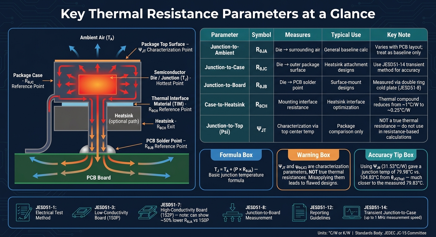
| Junction-to-Ambient | R<sub>θJA</sub> | Total resistance from the semiconductor die to the surrounding air; varies with PCB layout and test conditions |
| Junction-to-Case | R<sub>θJC</sub> | Resistance from the die to the outer package surface; relevant when attaching a heatsink directly |
| Junction-to-Board | R<sub>θJB</sub> | Resistance from the die to the PCB solder point; important for surface-mount designs |
| Case-to-Heatsink | R<sub>θCH</sub> | Resistance across the mounting interface; thermal compound can reduce this from ~1°C/W to ~0.25°C/W |
| Junction-to-Top (Ψ) | Ψ<sub>JT</sub> | Characterization parameter using the temperature at the package's top center |
The junction (T<sub>J</sub>) is the hottest point inside the device, located at the silicon die. The ambient (T<sub>A</sub>) represents the surrounding air temperature. The thermal path includes the case, board, and heatsink. As Siva Uppuluri, Applications Engineer at Diodes Incorporated, explains:
"Trying to measure the thermal resistance of a specific heat flow path like junction-to-case or junction to lead is complicated by the fact that the power dissipated at the semiconductor junction leaves the package through a number of parallel heat flow paths."
It's important to note that R<sub>θJA</sub> values in datasheets are derived from standardized JEDEC test boards. Your actual PCB layout - affected by factors like copper thickness, layers, and thermal vias - can significantly alter these values. Treat datasheet R<sub>θJA</sub> as a baseline rather than a guaranteed performance metric.
Webinar: Understanding Datasheet Thermal Parameters and IC Junction Temperatures
Thermal Resistance Standards Overview
Thermal Resistance Parameters Compared: Symbols, Reference Points & Use Cases
Standardized measurement methods make it easier for engineers to compare the thermal performance of various components. This consistency is crucial for ensuring effective thermal management, especially in compact and high-performance electrical designs. These standards help engineers choose the right components for dense applications with confidence.
JEDEC Thermal Resistance Standards

The JEDEC JC-15 committee is responsible for creating thermal standards widely used across the industry. Their primary objective is to ensure consistent test results, regardless of the laboratory conducting the tests. Jesse Galloway, a Member of Technical Staff at ON Semiconductor, emphasizes this point:
"The primary purpose for adopting and following a standard is to impose a common set of testing conditions so that equivalent results will be measured when the same packages are tested by different labs."
This uniformity ensures engineers can compare components from different manufacturers fairly, knowing that thermal performance data reflects actual design differences rather than testing discrepancies. The JESD51 series forms the backbone of these standards, covering everything from electrical testing methods (JESD51-1) to specific board designs and package configurations.
The choice of test board can significantly impact thermal resistance measurements. For instance, a high-conductivity 1S2P board (as defined in JESD51-7) can show a junction-to-ambient thermal resistance nearly 50% lower than a low-conductivity 1S0P board (JESD51-3) for the same package. This variation underscores the importance of referencing the correct board standard when interpreting datasheet values.
| Standard | Focus Area | Description |
|---|---|---|
| JESD51-1 | Electrical Test Method | Standard method for determining thermal characteristics of single IC devices |
| JESD51-3 | Low-Conductivity Board | Test board design for 1S0P configurations (single signal layer, no planes) |
| JESD51-7 | High-Conductivity Board | Test board design for 1S2P configurations (one signal layer, two internal planes) |
| JESD51-8 | Junction-to-Board | Conditions for measuring R<sub>θJB</sub> using a double ring cold plate |
| JESD51-12 | Reporting Guidelines | Common basis for reporting and using electronic package thermal information |
| JESD51-14 | Junction-to-Case | Transient dual interface method for measuring R<sub>θJC</sub> in single heat-path devices |
One standout standard is JESD51-14. Traditional steady-state methods for measuring R<sub>θJC</sub> often fall short because thermocouples placed on the case can disrupt heat flow. JESD51-14 addresses this by using high-speed transient temperature measurements - up to 1 MHz - allowing engineers to capture the thermal wave electrically before it exits the package, avoiding interference from thermocouples.
While JEDEC focuses on component-level thermal measurements, separate standards exist for evaluating thermal interface materials (TIMs).
Standards for Thermal Interface Materials
Thermal interface materials (TIMs) - like greases, pads, and phase-change films - have their own set of standards, distinct from JEDEC specifications. ASTM D5470 defines a guarded hot-plate method to measure both bulk thermal conductivity and overall thermal resistance under controlled conditions, such as bond-line thickness and applied pressure.
TIM performance is heavily influenced by bond-line thickness (BLT) and applied pressure. Since thermal resistance increases with BLT, even minor variations during assembly can significantly affect real-world results. Non-destructive methods like Scanning Acoustic Microscopy (SAM) or X-ray tomography are often used to verify BLT.
Thermal conductivity values for TIMs vary widely. For example:
- Greases and phase-change materials: 3–12 W/m·K
- Sintered metal films (used in high-power applications): 200–400 W/m·K
Qualification tests for TIMs also include reliability checks for issues like pump-out, oil bleed, and delamination. Failure is usually defined as a 10–20% increase in thermal resistance after thermal cycling.
sbb-itb-501186b
Using Thermal Resistance Standards in Compact Designs
Calculating Junction Temperature from Datasheets
The starting point for thermal calculations is the junction temperature formula: T₍j₎ = T₍a₎ + (P × R₍θJA₎). Here, T₍a₎ represents the ambient temperature, P is the power dissipation, and R₍θJA₎ is the junction-to-ambient thermal resistance. To find the maximum safe power dissipation, the formula can be rearranged as: P₍max₎ = (T₍j(max)₎ − T₍a₎) / R₍θJA₎.
Let’s break it down with an example. For a device with a maximum junction temperature of 150°C (302°F), an R₍θJA₎ of 150°C/W, and an ambient temperature of 25°C (77°F), the maximum power dissipation is approximately 0.83 W. This simple calculation forms the basis for understanding the more detailed thermal metrics discussed below.
Reading Datasheet Thermal Metrics
Datasheets present thermal metrics in two primary ways, as defined by the JEDEC standard JESD51-12.
- Method 1: This approach forces nearly all heat dissipation through a single path by using a large heatsink, providing a true thermal resistance value (R₍θJL₎).
- Method 2: This method accounts for total power dissipation without assuming a single heat flow path, resulting in a characterization parameter (like ψ₍th(JC)₎). However, ψ₍th(JC)₎ can appear deceptively low and may not be suitable for resistance-based calculations.
Siva Uppuluri, Applications Engineer at Diodes Incorporated, explains:
"For calculating junction temperature in real applications, Rth(JL) is unlikely to provide an accurate answer and more often gives the 'best case' result associated with maximum heat sinking."
This highlights the importance of understanding that relying solely on R₍θJA₎ or R₍θJL₎ can lead to inaccuracies, especially in real-world scenarios where heatsink configurations vary significantly.
PCB Design for Better Thermal Performance
Once you’ve grasped the thermal metrics, the next step is optimizing your PCB design to manage heat effectively in compact systems. One key strategy is enlarging the copper area around the device's lead frame tab beyond the Minimum Recommended Pad (MRP). This reduces R₍θJA₎ and lowers the device's junction temperature. It’s essential to align your PCB layout - factors like copper thickness, pad size, and via count - with the test conditions outlined in the datasheet.
Siva Uppuluri emphasizes:
"The differences in heatsink arrangements (volume and conductivity of the heatsink connected to the lead frame tab of the device) can cause significant errors when estimating the junction temperature using Rth(JA)."
To further improve thermal performance, consider these techniques:
- Add thermal vias under exposed pads to transfer heat to inner copper planes.
- Use thicker copper layers (e.g., 2 oz. instead of 1 oz.) to reduce spreading resistance.
- Measure the case temperature at the package surface center and correlate it with junction temperature using ψ₍th(JC)₎ for better accuracy.
These design adjustments often have a greater impact on thermal performance than the choice of components alone.
Common Mistakes and Best Practices
When working with thermal metrics, it's crucial to steer clear of common errors that can lead to inaccurate thermal management. Understanding the nuances of these metrics and their applications can make all the difference.
Misreading Standardized Metrics
One frequent mistake is misinterpreting thermal characterization parameters like ψ₍th(JC)₎ as actual thermal resistances. Let’s be clear: ψ₍th(JC)₎ is not a thermal resistance. Instead, it’s a characterization parameter designed for comparing different packages. Siva Uppuluri, Applications Engineer at Diodes Incorporated, explains:
"This value [ψ₍th(JC)₎] should not be treated as a true thermal resistance but only a thermal parameter and therefore should only be used for comparison between various packages."
This parameter can vary with temperature due to localized airflow, making it unsuitable for resistance-based calculations. Before using any metric, check if the datasheet adheres to JEDEC Method 1 (true thermal resistance) or Method 2 (characterization parameter). Misapplying these values can lead to flawed thermal designs.
Ignoring Interface and Mounting Conditions
Datasheet thermal resistance values are often tied to specific test setups, such as copper area, board size, and heatsink configurations. If your PCB layout differs from these conditions, your junction temperature estimates may be way off.
Another common error is misusing R₍θJL₎. This metric is derived under controlled conditions, like forcing heat through a single path with a large heatsink - scenarios that rarely reflect real-world PCB setups. Using R₍θJL₎ as a standalone calculation tool can result in overly optimistic predictions. For more accurate results, measure the case temperature at the center of the package surface and correlate it with junction temperature using ψ₍th(JC)₎, which tends to remain more consistent across various cooling setups compared to R₍θJA₎.
Omitting Transient Thermal Behavior
Steady-state metrics such as R₍θJA₎ are helpful for constant power conditions but fail to account for brief temperature spikes during switching events. These transient spikes can push the junction temperature beyond the device's maximum rated T₍j(max)₎, even if the long-term average seems acceptable.
Transient thermal behavior is influenced by both thermal resistance and thermal capacitance - essentially, the material's ability to store heat. To address this, standards like IEC 63378-6:2026 (published February 4, 2026) define compact thermal models using RC network topologies. These models are designed to predict how junction temperatures change over time under dynamic loads. Incorporating an RC-based transient model is especially important for power semiconductors in compact enclosures, as it helps anticipate dynamic junction temperatures during pulsed loads. This approach complements steady-state metrics, offering a more rounded perspective on thermal management.
Conclusion
Thermal resistance standards play a key role in ensuring safe and dependable compact electrical designs. They give engineers a consistent way to predict, compare, and manage heat effectively.
As Abdul Wassay, Electrical Engineer, explains:
"Temperature rise directly affects insulation life, operational safety, reliability, and long-term performance. Excessive heating can lead to premature failure, fire hazards, and costly downtime."
Understanding the difference between actual thermal resistance and characterization parameters, considering the effects of mounting conditions, and accounting for transient behaviors are all critical for creating designs that work as intended. These principles, outlined in this article, are the foundation for every stage of compact electrical system development.
When sourcing components, having clear thermal ratings is essential. Platforms like Electrical Trader provide a wide range of components that align with these standards.
FAQs
Which thermal metric should I use for my design: RθJA, RθJC, or Ψ?
The right metric to use depends on your specific design and environment. RθJA works well when comparing IC packages under standardized conditions, but it can vary significantly based on your board design and airflow. For power semiconductors equipped with a heat sink, RθJC is more relevant as it measures heat conduction directly to the case. To estimate junction temperature in practical applications, rely on Ψ (Psi) parameters like ΨJT, as these account for actual heat flow paths in real-world scenarios.
Why don’t datasheet Rθ values match my PCB’s real temperatures?
Datasheet RθJA values often don’t match real-world PCB temperatures. Why? Because they are influenced by factors such as PCB layout, copper density, substrate material, and airflow conditions. These values are typically calculated using JEDEC standards in controlled test setups that rarely mirror actual designs.
Since 70-95% of heat dissipation happens through the PCB, any differences in your specific setup can lead to junction temperatures that deviate significantly from what the datasheet predicts.
When do I need transient thermal modeling instead of steady-state Rθ?
Transient thermal modeling is essential for assessing how temperatures fluctuate over time and evaluating dynamic thermal performance. Unlike steady-state Rθ, which deals with equilibrium conditions, transient modeling considers thermal capacitance. This allows it to track heat flow during the initial stages of operation - down to microseconds before heat reaches the mounting base. This method is particularly important for time-sensitive simulations, such as those performed using the DXRC technique.


