Thermal Management Strategies for Power Generators
If a generator can’t move heat out, it loses output, wears parts faster, and may shut down when you need it most. I’d boil this article down to one point: thermal control is not just about cooling parts - it’s about protecting uptime, load capacity, and service life.
Here’s the short version:
- A generator turns only 35–45% of fuel into electricity. The rest becomes heat.
- Heat hits engines, alternators, bearings, and controls at the same time.
- Winding life can drop by about 50% for every 18°F (10°C) above its design temperature.
- Hot U.S. sites, indoor rooms, altitude, and air recirculation can eat up thermal margin fast.
- Air-cooled units fit smaller, lighter-duty jobs. Liquid-cooled units fit longer runtime and hotter sites.
- Large indoor sets may need remote radiators or heat exchangers instead of a unit-mounted radiator.
- Good installs depend on one-way airflow, low static pressure, correct coolant piping, and no hot-air loopback.
- A 500 kW indoor diesel unit often needs about 35,000–40,000 CFM of ventilation air.
- The main warning signs are high coolant temp, room heat, odd radiator ΔT, and rising oil temp.
- Before buying, I’d check ambient rating, derating curves, insulation class, radiator airflow, static limits, and coolant flow - not just kW.
How Generator Cooling Systems Work | Generator Source Tech Talk

sbb-itb-501186b
Quick Comparison
| Topic | What matters most | Common mistake |
|---|---|---|
| Cooling method | Match runtime, load, and site heat | Choosing by price alone |
| Generator room airflow | Keep air moving one way, out of the room | Letting hot discharge air recirculate |
| Radiator setup | Match fan and duct path to site layout | Ignoring static restriction |
| Coolant loop | Keep flow steady and vent air out | Long runs with too much pressure drop |
| Monitoring | Watch coolant, oil, room temp, and winding temp | Trusting one bad sensor reading |
| Equipment selection | Size for actual site conditions | Using nameplate output as-is |
If you want the article in one sentence: pick a generator and cooling setup for your hottest day, your highest load, and your site layout - not for lab conditions.
Core cooling methods and when to use them
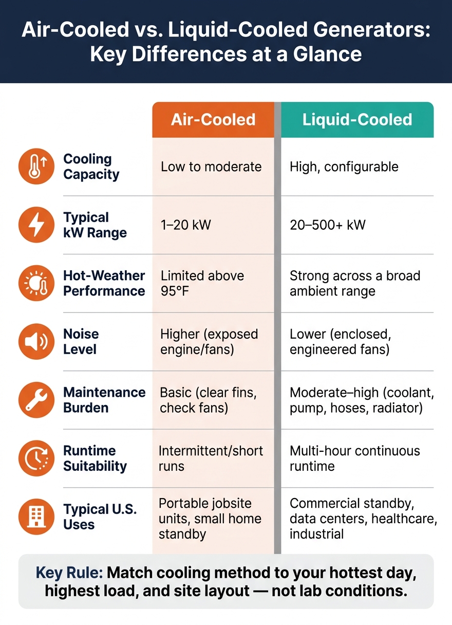
Air-Cooled vs. Liquid-Cooled Generators: Key Differences at a Glance
Air-cooled vs. liquid-cooled generator systems
Once you know the temperature limits, the next call is simple in theory but important in practice: how will the generator get rid of heat? At that point, cooling becomes a site-design issue. The right choice depends on unit size, runtime, site temperature, and how much upkeep the site team can handle.
Air-cooled generators shed heat by moving air over fins and exterior surfaces. Fans push that airflow across the engine and other hot parts. The setup is simpler, costs less, and is easier to service, which is why it works well for portable units and smaller residential standby generators - usually in the 1–20 kW range - that run now and then rather than all day. The tradeoff shows up in hot weather. As outdoor temperature climbs, cooling capacity drops and operating temperatures go up. Under continuous or heavy load, cylinder head and winding temperatures can climb enough to add wear and shorten insulation life.
That simple setup also limits how much heat the unit can handle. So when generator size grows, runtime stretches out, or the site stays hot for long periods, air cooling starts to run out of room.
Liquid-cooled generators handle heat in a closed loop. A water-glycol coolant moves through the engine block, picks up heat, travels to a radiator, and then releases that heat with the help of one or more fans before cycling back. A thermostat helps keep engine temperature steady as load moves up and down. In plain terms, this setup keeps temperatures more even across changing outdoor conditions, supports longer runtimes, and fits larger standby and industrial units better. It does come with more parts - hoses, a pump, a thermostat, and a radiator - and those parts need routine checks.
For multi-hour runtime or places that are hot on a regular basis, liquid-cooled systems are the better fit.
The table below shows where each method tends to work best.
| Cooling Method | Cooling Capacity | Typical kW Range | Noise | Maintenance Burden | Hot-Weather Performance | Typical U.S. Uses |
|---|---|---|---|---|---|---|
| Air-cooled (natural/forced) | Low to moderate | 1–20 kW | Higher (exposed engine/fans) | Basic (clear fins, check fans) | Limited above 95°F | Portable jobsite units, small home standby |
| Liquid-cooled | High, configurable | 20–500+ kW | Lower (enclosed, engineered fans) | Moderate–high (coolant, pump, hoses, radiator) | Strong across a broad ambient range | Larger homes, commercial standby, data centers, healthcare, industrial |
Remote radiators, heat exchangers, and cooling for large generators
When a generator sits inside a building - think data centers, hospitals, or industrial plants - heat rejection stops being just a machine issue. It becomes a layout issue too. A unit-mounted radiator works fine outdoors or in a basic room with a short, direct duct path to the outside. But once the room is fully enclosed, the duct run gets long, or noise rules tighten up, that setup starts to hit a wall.
Remote radiators shift the heat rejection surface outside, usually to a rooftop or ground-level pad, and connect back to the generator with coolant piping. That sounds clean on paper, but the pipe design matters a lot. If pipe sizing, routing, or pump selection is off, flow drops and temperature rises. On larger systems or taller buildings, a booster pump or separate circulation pump is often added to keep flow where it needs to be. In colder parts of the U.S., venting, expansion tanks, and freeze protection also matter.
Some sites already have chilled water systems or cooling towers. In those cases - common in hospitals, campuses, and large industrial plants - a shell-and-tube or plate heat exchanger can take the radiator’s place. The generator’s primary coolant loop dumps heat into the building’s secondary cooling loop, which helps keep hot air and big radiator fans out of the generator room.
At the utility scale, the cooling setup changes again. Hydrogen cooling is used in roughly the 250–450 MW range because hydrogen has high thermal conductivity and low density, which cuts windage losses and moves heat better than air. The largest machines, up to about 1,800 MW, pair hydrogen cooling for the rotor with water-cooled hollow stator conductors. These systems need sealed enclosures, constant checks of hydrogen purity and pressure, carbon dioxide (CO2) purging during startup and shutdown, and staff with special training.
The table below compares the main cooling configurations used in U.S. generator installations and where each one fits best.
| Configuration | Space Needs | Installation Complexity | Typical U.S. Uses | Thermal Advantages / Constraints |
|---|---|---|---|---|
| Unit-mounted radiator | Adjacent to generator; clear duct path to outdoors | Low (integrated package) | Small to medium commercial outdoor sets, schools, light industrial sites | Predictable, integrated performance; limited by duct length and room static pressure |
| Remote radiator | Rooftop or ground pad; coolant piping runs | Medium–high (hydraulic design, structural support, insulation) | Large commercial and industrial indoor rooms, data centers, high-rise buildings | Flexible placement, separates heat and noise from occupied areas; requires booster pumps for tall or long runs |
| Heat-exchanger-based | Mechanical room space; piping manifolds and control valves | High (integrated with building cooling systems) | Major hospitals, industrial plants, campuses with central chilled water or process cooling loops | High efficiency, uses existing cooling capacity; needs coordination with building systems and enough secondary loop capacity |
Even the best cooling setup fails if the site can’t support the heat path. In the end, cooling choice only works when airflow, piping, and radiator placement all line up with the layout.
Installation practices that prevent overheating
Once you pick the cooling method, the next step is where many setups go wrong: installation. A system can look fine on paper and still run hot if the room, airflow path, or coolant loop isn't laid out the right way.
Generator room ventilation, airflow path, and heat rejection
Ventilation has one job: move heat out of the room instead of letting it build up. That means the room should support one-way airflow. Put intake louvers low at the alternator end, and place discharge openings high at the radiator end.
Just as important, don't let radiator discharge air circle back into the room. That hot-air recirculation is a common cause of overtemperature shutdowns. A flexible canvas or rubber bellows duct that connects the radiator shroud straight to the discharge wall opening helps stop hot air from spilling back inside.
Airflow should be sized from the generator's heat-rejection data, not from room size. Use this formula:
CFM = Heat Rejection (BTU/hr) ÷ (1.08 × ΔT °F)
A good target is a room temperature rise of 10–18°F above outdoor intake temperature. In hot climates, aim tighter at 5–10°F. The point is to keep room temperature below the 95–104°F limit that most manufacturers set for full-rated output. For a useful reference point, a 500 kW diesel genset installed indoors typically requires 35,000–40,000 CFM of ventilation air.
Then there's static pressure, which often gets missed. Louvers, filters, grilles, and ductwork all add resistance. Most standard engine-driven radiator fans are rated for a maximum external static restriction of about 0.2 in. H₂O - roughly 120–150 Pa - across the full intake-to-discharge path. Go past that limit and airflow falls off, which is when temperatures start creeping up.
| Design Parameter | Typical Target Value | Notes |
|---|---|---|
| Required ventilation airflow | 35,000–40,000 CFM (500 kW diesel) | Use CFM = BTU/hr ÷ (1.08 × ΔT); scale by unit size |
| Allowable static restriction | ≤0.2 in. H₂O (intake + discharge combined) | Confirm against the genset data sheet; add a high-static fan option if needed |
| Room temperature rise | 10–18°F above outdoor intake; 5–10°F for hot climates | Keep room below 95–104°F to avoid derating |
| Exhaust radiant heat load | Varies; add to total BTU/hr for ventilation sizing | Insulate exhaust components inside the room to reduce this load |
| Altitude airflow adjustment | +10% per 2,500 ft above sea level | Accounts for reduced air density at elevation |
Exhaust piping inside the room adds another heat load, and it doesn't come from the radiator. Uninsulated manifolds, turbochargers, and flex connections all throw heat into the space. That extra BTU load needs to be added to the total heat rejection used in the ventilation calculation. Insulating exhaust parts inside the room helps cut that load down.
Coolant circuit layout, radiator placement, and heat recovery
Room airflow deals with ambient heat. After that, the coolant circuit has to carry engine heat away without trapping air or asking too much from the pump.
Coolant layout has a direct effect on heat transfer and air removal. The surge tank should sit at the highest point in the system so it can collect air and keep the coolant column full as the loop warms from startup to operating temperature. Every high point in the circuit needs either a vent or a line back to the surge tank so the system can fully deaerate during initial fill.
Pipe size and routing matter more than people think. Long pipe runs, small diameters, and too many fittings all add friction. If total pressure drop goes beyond what the engine-driven pump can handle, coolant flow drops and engine temperature goes up. With remote radiators on tall buildings or on long horizontal runs, a booster pump is often the better fix than trying to make every pipe bigger. Designers also need to factor in elevation difference between the engine and radiator, since vertical lift adds static head on top of friction losses.
This gets even more important when the radiator is remote or when the loop also supports heat recovery. In CHP systems, a plate or shell-and-tube exchanger can recover jacket-water and exhaust heat for building hot water, process heating, or space heating. But the engine still needs a path to dump heat when that recovery side can't take the load. That's why a three-way thermostatic valve and bypass loop need to be in place so heat can still go to the radiator.
Exhaust heat recovery has its own limit: backpressure. The total exhaust system restriction - including silencers, piping bends, and the recovery unit - has to stay within the engine manufacturer's maximum allowable value. If it doesn't, power output drops, exhaust temperatures go up, and engine damage can build over time. The only dependable way to check this is during commissioning, with measurements taken at rated load.
Monitoring, maintenance, and troubleshooting cooling performance
Once the cooling system is in place, day-to-day performance comes down to watching the right temperatures and stepping in before a warning turns into a shutdown.
Sensors, alarms, controls, and protective shutdowns
Cooling only works when the right points are being monitored. Track coolant temperature, engine oil temperature, room temperature, radiator inlet and outlet temperatures, and winding RTD readings on larger units.
Of those, coolant temperature is the main early warning sign. Many diesel generator controls issue a high-temperature warning before shutdown. Shutdown is often set near 221°F (105°C). Winding alarms and trips should be based on the allowed insulation temperature, while the coolant high-temperature warning should be treated as the first point to act, well before the 221°F shutdown limit.
Radiator ΔT gives you a fast read on heat transfer. At rated load, a radiator ΔT of 27–45°F is normal. If it drops below 18°F, look for blockage or loss of airflow. If it climbs above 54°F, low coolant flow, a weak pump, or a stuck thermostat is more likely.
On most diesel engines, thermostats start opening around 176–185°F (80–85°C) and are fully open near 203°F (95°C). For hot sites or high-altitude locations, use the manufacturer’s derating curves.
It also helps to send these signals into SCADA or BMS. That gives you alerts, trend logs, and condition-based maintenance data.
Common overheating faults and maintenance checks
Most overheating cases come from a short list of root causes. The way temperature builds usually tells you where to look first. Fast spikes at startup or at low load often point to coolant loss, a failed pump, or a thermostat stuck closed. Slow temperature climbs over several hours at moderate load usually mean blocked radiator fins, dirty intake vents, or poor room ventilation.
A few routine checks prevent most of these problems:
- Clean radiator fins with low-pressure compressed air from the engine side outward so trapped debris gets pushed clear.
- Test thermostats in hot water to make sure they begin opening at 176–185°F. A thermostat stuck closed can cause fast overheating, while one stuck open keeps the engine from reaching normal operating temperature.
- Keep the right water/antifreeze/inhibitor mix to limit scale and corrosion.
- Flush the coolant system about every 2 years or 500 operating hours, based on OEM guidance.
The table below covers the fault patterns seen most often in U.S. commercial and industrial facilities:
| Symptom | Likely Cause | Recommended Check |
|---|---|---|
| Rapid coolant temperature spike at startup or low load | Low coolant, pump or thermostat failure | Inspect coolant level; check for leaks; verify pump belt tension and thermostat operation |
| Gradual temperature rise at moderate load | Blocked fins, dirty vents, poor ventilation | Check radiator and intake vents for debris; clean fins; confirm louvers are fully open |
| Room temperature above 104–113°F | Undersized ventilation, closed dampers, or hot-air recirculation | Measure intake and discharge airflow; check louver actuators; verify discharge air is not recirculating |
| Reduced radiator ΔT at normal load | Fouled fins, internal blockage, or poor airflow | Clean radiator externally; check coolant flow rate; flush if internal scale is suspected |
| High oil temperature with normal coolant temperature | Oil cooler restriction or increased internal friction | Inspect oil cooler airflow path; check for signs of increased internal friction |
| Frequent high-temp alarms in summer only | Insufficient derating for ambient or altitude | Apply manufacturer derating curves; verify alarm thresholds match site conditions |
| Erratic or implausible temperature readings | Faulty sensor, wiring fault, or miscalibrated input | Inspect sensor connectors for corrosion and loose terminals |
One sensor spike by itself should be treated with caution until nearby readings back it up. If a single alarm appears out of place, verify it with an IR thermometer before calling it overheating. Real overheating shows up across multiple readings at once - coolant temperature, oil temperature, and room temperature - not just one odd signal.
These same readings also tell you if a generator has enough thermal margin for the site.
Selecting thermally suitable equipment and key takeaways
What to check before buying generators and cooling components
Once installation and maintenance checks are done, the last step is simple: buy equipment that can handle the load in your actual site conditions.
That matters because thermal limits only count if the unit you buy can still deliver the output you need where it will run. Nameplate kW doesn't show real output at your site. A unit rated at sea level and 77°F can lose 10%–20% at 104°F and 5,000 ft, depending on the derating curve. So before you buy, check the derating curve for your worst-case ambient temperature and elevation, then confirm the unit's continuous kW at those conditions.
Use these datasheet items to screen out undersized or poorly matched equipment:
| What to check | Why it matters |
|---|---|
| Maximum ambient temperature rating | Confirms whether the unit can run at full load during summer heat waves at your site |
| Derating curves for temperature and altitude | Shows how available kW changes as ambient temperature rises or elevation increases |
| Insulation class and temperature rise | Match insulation class and temperature rise to your site's heat load and required service life. Higher insulation class and lower temperature rise give more thermal margin and longer winding life in hot climates. |
| Radiator airflow (CFM) and heat rejection capacity | Determines whether the cooling system can handle the heat load under the installed ductwork and enclosure conditions |
| Allowable static restriction | Sets the maximum duct and grille resistance the radiator fan can tolerate before airflow drops below what's needed |
| Coolant volume and flow rate | Ensures the pump and radiator can maintain stable temperatures at peak load without localized hot spots |
If you're sourcing equipment through Electrical Trader, compare the full thermal datasheet, not just kW and voltage. That's where buyers get tripped up. Two units can look the same on paper, yet have very different cooling limits.
For marketplace purchases, check the cooling package, enclosure changes, and fan/static limits against the original datasheet. Make sure the radiator, fans, and pumps are intact. Also confirm that no enclosure or silencing changes push static restriction past the manufacturer's allowable limit.
Conclusion: The thermal management points that matter most
That's the core idea behind thermal management: it isn't only about avoiding trips. It's about protecting usable capacity.
Choose thermal margin first. A low-price unit stops being cheap if it derates, trips, or wears out early. Better thermal management means fewer shutdowns, longer component life, and more predictable operating cost.
FAQs
How do I know if my generator is losing power from heat?
Watch for small but steady shifts in performance, especially rising lube oil or engine temperatures, even when they remain below alarm limits. Those small changes can be early signs that something’s off.
Real-time monitoring can also spot unusual patterns in temperature, vibration, and airflow. That matters because heat issues don’t always show up as one big spike. Sometimes they show up as a pattern that slowly drifts in the wrong direction.
Other warning signs include:
- Reduced cooling flow
- Restricted airflow
- Higher power use by compressors or cooling parts
These signs often point to heat-management problems that can cut generator output.
When should I choose a remote radiator instead of a unit-mounted one?
Choose a remote radiator when the installation environment calls for targeted heat control. It’s an active cooling option that works well when natural ventilation can’t deal with the equipment’s heat load.
It’s especially useful for high heat loads in primary distribution systems or in enclosed spaces where airflow needs to be pushed away from the equipment.
What should I verify before buying a generator for a hot or high-altitude site?
Check that the generator is rated for de-rating conditions at high elevations and in extreme heat. As air gets thinner, the unit loses efficiency, and fuel use can climb by 6% to 8% for every 3,280 feet of elevation.
With diesel generators, fuel consumption also goes up by about 2% for every 9°F above 95°F. That matters because a generator that looks fine on paper can struggle in hot, high-altitude conditions.
The goal is simple: make sure the generator can carry your required load without overheating or putting extra strain on the engine.