How to Test Soil Resistivity for Transformer Grounding
If I want a grounding system that works, I test the soil first. A simple four-pin Wenner test tells me how hard it is for fault current to move into the earth, and that drives choices like rod depth, grid size, and whether I may need extra treatment around electrodes.
Here’s the short version:
- Soil resistivity is measured in ohm-meters (Ω·m) and changes with moisture, temperature, and soil type.
- Low resistivity soil is easier to ground. High resistivity soil makes grounding harder and can push step and touch voltages higher.
- I use the Wenner four-pin method with equal stake spacing, then apply ρ = 2πaR.
- I test at multiple spacings - for example 3, 6, 16, 33, 50, 66, 100, and 165 ft - to get a picture of shallow and deeper soil.
- I repeat each reading three times and look for results within about 5% to 10% of each other.
- As rough guides, soil below 100 Ω·m is usually easier to work with, while soil above 1,000 Ω·m often needs more grounding effort.
- Before any test, I handle LOTO, PPE, utility locating, and weather checks.
This process is not just about getting a number. It helps me see whether deep rods, a horizontal grid, or added material around electrodes makes more sense for the transformer site. The goal is simple: get field data first, then build the grounding design around the soil that is actually there.
Soil Resistivity Testing Explained: Wenner Method & Polar Curve Analysis for Grounding System Design
sbb-itb-501186b
Tools, Test Setup, and Site Preparation
Get your gear together before you head into the field. That simple step helps you avoid delays, bad contact, and weak readings later on. For a Wenner four-pin soil resistivity test, you’ll need a four-terminal soil resistivity tester, four auxiliary ground stakes, insulated test leads and clips, a tape measure of at least 100 ft, a hammer or stake driver, and marking tools to lay out the stake positions along the test line.
Once the site is clear, set out the meter, stakes, leads, and layout tools so everything is ready to go.
| Equipment | What It Does |
|---|---|
| Soil Resistivity Tester | Injects current through the outer stakes and measures voltage at the inner stakes to calculate resistivity |
| 4 Ground Stakes | Creates the physical contact points with the soil |
| Insulated Leads | Connects the meter terminals (current and potential terminals) to each stake |
| Tape Measure (≥100 ft) | Ensures equal stake spacing required by the Wenner formula |
| Hammer/Driver | Drives stakes firmly into the ground for solid electrical contact |
| Marking Tools | Marks stake locations along the test line |
These tools support the Wenner method and help turn field readings into grounding design data.
Recommended Test Instruments and Accessories
Two testers you’ll often see on U.S. job sites are the Megger DET2/2 and the Fluke 1625-2. Both support the Wenner four-pin method. Before fieldwork, make sure the unit is calibrated based on the manufacturer’s recommendations.
Use the readings to place the test line where it best reflects the transformer site.
How to Choose Straight Test Lines That Represent the Site
Set the test lines as close as you can to the planned transformer grounding area so the readings match the soil the ground grid will sit in. The line should run straight across soil that reflects the area well, not across surface features that can throw the readings off.
Stay away from buried metal pipes, active ground grids, fences, and paved surfaces. Those can create low-resistance paths and skew the results. Keep the test line at least 100 ft from the transformer area so the reading reflects native soil.
If the soil is layered or uneven, run at least two test lines at 90-degree angles to each other. That gives you a better picture of uneven soil conditions.
With the line marked, you can move on to stake spacing and meter connections.
How to Perform a Wenner Four-Pin Soil Resistivity Test
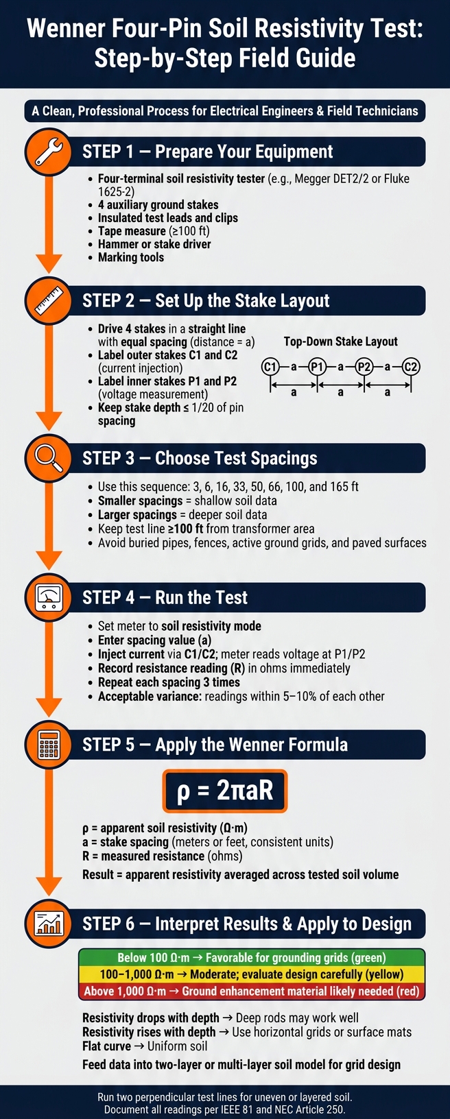
Wenner Four-Pin Soil Resistivity Test: Step-by-Step Field Guide
Once the test line is marked, run the Wenner sequence from the smallest spacing outward.
The Wenner four-pin method is the standard field test for transformer grounding because it gives you the data needed for grounding design. The setup is simple: drive four stakes in a straight line with equal spacing, labeled a. The two outer stakes, C1 and C2, send current into the soil. The two inner stakes, P1 and P2, measure the voltage drop that follows. Because current and voltage are handled by separate stakes, rod contact resistance is left out of the calculation.
Set Stake Spacing, Depth, and Meter Connections
Start with short spacings, then work outward. This helps map shallow and deeper soil layers. A practical sequence is 3, 6, 16, 33, 50, 66, 100, and 165 ft. Smaller spacings reflect shallow soil conditions, while larger spacings reflect deeper conditions.
Keep stake depth shallow, about 1/20 of pin spacing or less. Place the stakes in a straight, even line. Then connect C1 and C2 to the outer stakes and P1 and P2 to the inner stakes.
Run the Test and Repeat Readings for Consistency
Set the meter to soil resistivity mode, enter the spacing value, and run the test. The meter will show a resistance value (R) in ohms. Write it down right away with the spacing and the test line direction.
Run each spacing three times and average the results. The readings should stay within 5–10% of each other. If they jump around, improve stake contact or moisten the soil with water.
Apply the Wenner Formula and Use Multiple Spacings
Record each spacing and resistance reading before you calculate resistivity.
After you get a stable resistance reading (R) for a given spacing (a), calculate apparent soil resistivity with the simplified Wenner formula:
ρ = 2πaR
Here, ρ is apparent resistivity, a is the stake spacing, and R is the measured resistance. Use the same unit system all the way through the calculation.
What you get is apparent resistivity - an average across the soil volume tested. Those spacing patterns are then used to build the soil model for grounding design, which helps guide ground grid sizing and placement.
How to Read and Use Soil Resistivity Results for Grounding Design
Once you've converted the Wenner readings into resistivity, the next step is to turn that raw data into a soil profile. Put the electrode spacing, measured resistance, and calculated resistivity into a table, then plot resistivity against spacing. That chart helps you see what the soil is doing below the surface instead of just looking at a string of numbers.
Identify Soil Conditions and Layering From the Data
The shape of the curve tells the story.
If resistivity drops as spacing gets larger, the deeper soil is more conductive. In plain terms, that usually means deep-driven ground rods can work well. If resistivity climbs with spacing, you're probably hitting bedrock or dry, compacted material at depth. In that case, horizontal grids or surface mats tend to make more sense. If the curve stays mostly flat across all spacings, the soil is fairly uniform, although that doesn't happen often in the field.
A couple of rule-of-thumb ranges help here:
- Below 100 Ω·m, soil is usually favorable for grounding grids
- Above 1,000 Ω·m, you may need ground enhancement material to hit safe resistance targets
Use the resistivity data to shape the grounding design first. After installation, confirm the finished system with ground-resistance testing.
Connect Test Results to Ground Grid and Equipment Decisions
Wenner readings don't go straight into grid design as-is. Engineers usually fit the data to a soil model first. In many cases, they use computerized least-squares regression to build a two-layer or multi-layer model, then use that model to check step and touch voltage limits for the site. From there, the model affects major design choices like:
- Grid footprint
- Conductor spacing
- Rod depth
- Whether ground enhancement materials are needed
When resistivity is high and rods alone won't get resistance low enough, ground enhancement materials (GEM), such as bentonite or conductive concrete, can be placed around electrodes to improve contact with the surrounding soil.
It's also smart to run traverses in two perpendicular directions. This helps you spot site variation. If the two curves split far apart, subsurface metallic interference or geologic variation may be skewing the readings. Don't size the final grid until you know why that's happening. If you see a split curve or any interference, document it in the project file.
Troubleshooting, Documentation, and Final Takeaways
If the resistivity plot looks unstable, stop and check the setup before you trust the data. A shaky curve often comes from simple field issues: swapped or loose leads, poor stake contact, or loose clip connections. In plain terms, a small setup mistake can throw off the whole line.
Another common problem shows up when the outer current stake sits too close to the grounding system. When that happens, the curve may keep rising instead of leveling off. The fix is simple: move the stake farther out and run the test again. If readings jump around, check the setup first before assuming the soil is the problem.
Once you correct any bad readings, verify the spacing and make sure each point was measured right. A second traverse is only needed if the first line looks skewed by subsurface interference or uneven soil.
Check Readings and Keep Usable Field Records
Use the same format for every run so the engineer can compare lines and spacings without digging through messy notes. Good records also support compliance with NEC Article 250 and IEEE 81.
| Field | What to Record |
|---|---|
| Location | GPS coordinates or site address |
| Date/Time | MM/DD/YYYY format, with local time |
| Weather and soil | Recent rainfall or dry spells, soil moisture, temperature if relevant, and visible soil type (sandy, rocky, damp) |
| Instrument | Model, serial number, and calibration status |
| Test Direction | Compass bearing or reference to a fixed landmark |
| Stake Spacing | Each Wenner spacing used, in feet |
| Measured Resistance | Raw ohm reading at each spacing |
| Calculated Resistivity | Final Ω·m value from the Wenner formula |
These records also support soil modeling and compliance with NEC Article 250 and IEEE 81.
FAQs
When should I test soil resistivity for a transformer site?
Test soil resistivity before installing a new transformer site. This step matters because it helps you find the part of the site with the lowest soil resistivity, which can lead to the most cost-effective and effective grounding system.
Testing before construction also helps you figure out the right depth and placement for ground electrodes. It can also confirm that the site meets safety and performance requirements.
How many Wenner test lines should I run?
Run multiple Wenner test lines, or traverses, to get an accurate soil resistivity assessment. In most cases, at least three traverses across the site are a good idea. That helps confirm soil trends and spot stray readings or testing errors.
Take the traverses in different directions, like right angles and diagonals, so you can account for changes in the soil across the site. On larger sites, increase electrode spacing along these lines to check for deeper geological shifts.
What causes inaccurate soil resistivity readings?
Inaccurate soil resistivity readings usually come down to the site itself or the way the test is run. Buried metal, nearby structures, uneven ground, and electromagnetic interference can all skew the numbers.
Problems also show up when teams skip multiple perpendicular traverses, fail to resolve surface layers at short spacings, use too little probe spacing, or make mistakes during unit conversion.