




How Solar Plants Select Medium Voltage Transformers
Pick the transformer by plant role first, then check five things: load, voltage match, impedance and grounding, site heat, and code. If any one of those is off, you can end up with trips, overheating, poor load sharing, or a unit that does not fit utility rules.
Here’s the short version:
- I start with the one-line diagram, not the DC array size.
- I size from inverter AC output in kVA/MVA, then add about 10%–20% margin.
- I match LV/MV voltage, tap range, vector group, % impedance, and grounding to the collection system and relay scheme.
- I check site limits like 104°F (40°C) ambient design, altitude above 3,300 ft, cooling type, and enclosure rating.
- I verify NEC, IEEE C57, DOE efficiency, utility paperwork, and factory test reports before release.
A few numbers drive most of the decision:
- kVA = kW ÷ power factor
- A 3,000 kW inverter at 0.95 PF needs about 3,158 kVA
- Four of those units total about 12,632 kVA
- Add 15% margin and you land near 14,527 kVA, so I would move to a 15 MVA transformer
- Common impedance ranges are about 5%–10%, and that directly changes fault current and voltage drop
You also have to treat transformer types differently. An inverter step-up unit, a collector transformer, and a main interconnection transformer may all sit in the same solar plant, but they do different jobs and face different utility demands. That is where many buying mistakes start.
If you want the fast checklist, it’s this:
- Use AC nameplate data
- Round up to the next standard size
- Match voltage ratio and winding setup
- Check heat, altitude, cooling, and enclosure
- Review code, utility rules, and test documents
| Transformer role | Main job | What I check first |
|---|---|---|
| Inverter step-up | Moves inverter output to MV collection voltage | AC output voltage, kVA, vector group |
| Collector transformer | Combines feeder or block power | MV ratio, impedance, load sharing |
| Main interconnection | Steps plant MV to utility voltage | MVA, utility specs, fault duty, testing |
In other words: the right transformer is not just “big enough.” It has to fit the plant’s electrical setup, the site’s heat and altitude, and the utility’s rules before it is ordered.
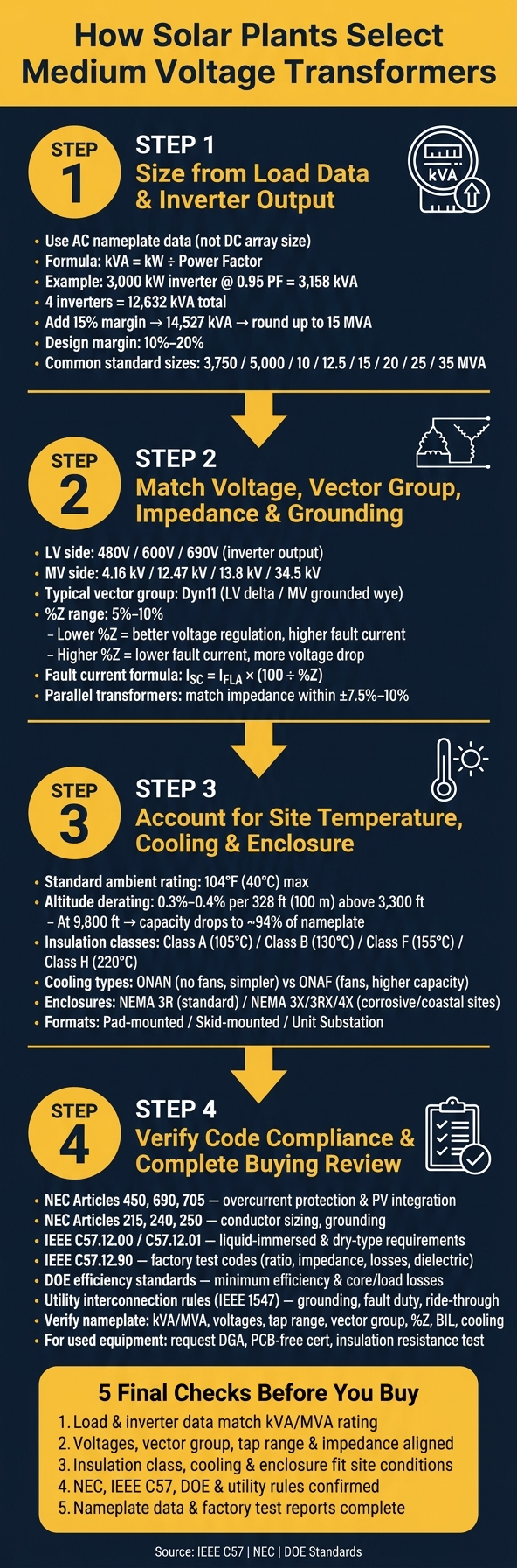
How to Select a Medium Voltage Transformer for Solar Plants: 4-Step Checklist
The Most Important Factors When Specifying a Transformer
sbb-itb-501186b
Step 1: Size the Transformer From Load Data and Inverter Output
Start with the AC nameplate data, not the DC array size. That’s the number that should drive transformer sizing.
For each inverter, record:
- kW or kVA
- AC output voltage
- power factor range
- how many inverters feed each transformer
Once you’ve set the kVA, make sure the transformer also matches the required voltage, vector group, impedance, and grounding.
Use Inverter AC Ratings, Duty Cycle, and Expansion Margin
If the datasheet lists kW and power factor, convert to kVA with kVA = kW ÷ PF. If the interconnection agreement calls for reactive power support, size to the worst-case power factor. For example, a 3,000 kW inverter at 0.95 PF needs about 3,158 kVA.
Use peak apparent power for sizing, not average output. Temporary overload limits can help in a pinch, but they should not be the basis for the transformer size.
After you add up the kVA for all inverters on the transformer, include a 10%–20% design margin before picking a standard size. Use the high end if you expect future expansion, hot site conditions, or frequent reactive power operation. For example, four 3,000 kW inverters at 0.95 PF total about 12,632 kVA. Add a 15% margin, and the result is about 14,527 kVA. That rounds up to a 15 MVA transformer.
Common standard sizes for pad-mount and collector transformers include 3,750 kVA, 5,000 kVA, 10 MVA, 12.5 MVA, 15 MVA, 20 MVA, 25 MVA, and 35 MVA. Always round up to the next standard size.
Before you lock in the number, check it against the inverter datasheets, the one-line diagram, and the interconnection documents. Small mismatches here can turn into expensive mistakes later. Say the one-line shows more inverters on a transformer than the sizing sheet assumed. In that case, fix the kVA total before procurement. After the size is set, verify the electrical fit and protection details.
Step 2: Match Voltage, Vector Group, Impedance, and Grounding
Once you've confirmed kVA size, the next step is making sure the transformer's electrical setup fits the rest of the system. In plain English: the voltage ratio, winding arrangement, grounding, and impedance all need to line up before you buy the unit.
Select the Correct Voltage Ratio and Tap Range
Start with the voltage ratio.
The transformer low-voltage side should match the inverter AC output, which is usually 480 V, 600 V, or 690 V, three-phase. The medium-voltage side should match the collector or interconnection voltage, usually 4.16 kV, 12.47 kV, 13.8 kV, or 34.5 kV.
In U.S. projects, 12.47 kV is a common distribution voltage. 34.5 kV shows up a lot in larger solar collector systems and utility tie points.
Utility voltage doesn't stay perfectly fixed, so the transformer also needs taps to make up for that drift. A common choice is ±5% off-circuit taps in 2.5% steps. The final tap position is then set during commissioning after the utility voltage is measured.
Check Vector Group and Percent Impedance Against Protection Needs
Connection type matters more than it might seem at first glance. Delta or wye, plus where the neutral sits, affects grounding, harmonics, and how protection relays behave.
For solar step-up transformers, a common setup is LV delta / MV grounded wye, often written as Dyn11. That arrangement does two big jobs:
- The delta winding helps isolate the inverter side from system ground and gives third-harmonic currents a circulating path, so they don't pass through to the utility.
- The grounded wye MV winding gives protection relays a neutral reference, which lets ground-fault functions like 51G and 67N operate the way they're supposed to.
Then there's percent impedance, or %Z. This number affects both fault current and voltage drop under load.
Lower impedance, around 5% to 6%, usually gives better voltage regulation. The trade-off is higher short-circuit current, which puts more stress on breakers and relays.
Higher impedance, around 8% to 10%, cuts fault current and can make protection coordination easier. But it also increases voltage drop, which can hurt inverter ride-through during grid disturbances.
The relationship is simple:
I_SC = I_FLA × (100 ÷ %Z)
So when impedance drops, fault current goes up. That's the give-and-take.
The table below lays out common voltage ratios, usual vector groups, and what lower versus higher impedance tends to mean in solar plant service:
| LV / MV Voltage Ratio | Typical Vector Group | Typical %Z Range | Lower Impedance | Higher Impedance |
|---|---|---|---|---|
| 480 V / 12.47 kV | Dyn11 (LV delta / MV grounded wye) | 5–8% | Better voltage regulation; higher fault current | Lower fault current; more voltage drop |
| 600 V / 13.8 kV | Dyn11 (LV delta / MV grounded wye) | 5–8% | Tighter voltage control at full output | Easier protection coordination |
| 690 V / 34.5 kV | Dyn11 (LV delta / MV grounded wye) | 6–10% | Strong fault current for reliable relay tripping | Helps meet utility fault current limits at POI |
If multiple transformers will share one MV bus, their impedance values need to be close. A common target is within about ±7.5% to 10% of each other. If they drift too far apart, one transformer can end up carrying more than its share of the load. So yes, matching impedance within ±7.5% to 10% is a practical way to keep paralleled transformers sharing load evenly.
After the electrical fit is nailed down, the next check is temperature, insulation class, cooling, and enclosure rating.
Step 3: Account for Site Temperature, Insulation Class, Cooling, and Enclosure
Once voltage and impedance are matched, thermal limits become the next filter. After those two items are set, check whether the transformer can deliver full output at the site's worst heat and altitude.
Adjust for Ambient Temperature, Altitude, and Insulation Limits
Most medium-voltage transformers are rated for a maximum ambient temperature of 104°F (40°C) and a 24-hour average of about 86°F (30°C). At desert and southern U.S. solar sites, long periods of high heat, direct sun, dust, humidity, and repeated daily load cycling can eat into thermal margin and speed up insulation aging.
Ambient temperature and winding temperature rise are not the same thing. At 86°F (30°C) ambient, a standard 65°C-rise transformer can reach a hot-spot winding temperature near 248°F (120°C). And each added 7°C in hot-spot temperature can roughly double the insulation aging rate. So the kVA size confirmed in Step 1 still has to work at the site's worst-case ambient temperature and altitude.
Altitude matters too. Above 3,300 ft (1,000 m), derate about 0.3% to 0.4% per 328 ft (100 m). By 9,800 ft (3,000 m), usable capacity can fall to around 94% of nameplate. In plain terms, thinner air means less cooling.
Representative insulation classes and temperature-rise ranges are shown below:
| Insulation Class | Max Winding Temp | Typical Temp Rise | Solar Project Fit |
|---|---|---|---|
| Class 105 (A) | 221°F (105°C) | 55°C rise | Temperate sites with moderate loading |
| Class 130 (B) | 266°F (130°C) | 80°C rise | Moderate climates |
| Class 155 (F) | 311°F (155°C) | 65°C rise | Hot sites with higher duty cycles |
| Class 220 (H) | 428°F (220°C) | 80–150°C rise | Desert utility-scale projects with limited ventilation |
These are representative values, and exact limits vary by manufacturer and design. For hot sites with heavy daily cycling, it usually makes sense to pair a higher insulation class with a lower temperature rise. Before approval, ask the vendor to confirm rated performance at your site's worst-case ambient temperature and altitude, and get any derating assumptions written into the purchase specification.
Choose a Cooling Method and Outdoor Enclosure Format
If the thermal class is fixed, cooling method becomes the next constraint.
ONAN (oil natural, air natural) is the simpler path: no fans, no controls, and less maintenance. It fits sites where the load stays within normal limits and airflow around the equipment is decent. ONAF (oil natural, air forced) adds fans to increase cooling capacity when ambient temperatures run high or the transformer needs more headroom for peak output. The trade-off is simple enough: more cost, fan controls, and another maintenance item to watch.
For indoor installations, inverter buildings, or any location where fire risk or oil containment is a concern, dry-type or cast-resin units are often the better fit. They reduce oil-spill risk and can line up better with permitting needs or owner standards that discourage liquid-filled equipment.
Enclosure format also affects layout and construction from day one:
| Enclosure Format | Installation Complexity | Maintenance Access | Best Environment | Typical Solar Use |
|---|---|---|---|---|
| Pad-Mounted | Moderate; requires concrete pad | Front-access cabinet | Outdoor, ground-level | Standard utility-scale arrays with underground feed |
| Skid-Mounted | Lower field labor; prefab-friendly | Open or enclosed access | Outdoor/industrial | Modular "power block" designs; remote sites |
| Unit Substation | Higher; integrated with switchgear | High; packaged access | Indoor or outdoor | Large plants requiring integrated MV switching |
NEMA 3R is a common starting point for rain and sleet protection. But if the site deals with windblown dust, sand, salt air, or other corrosive exposure, you may need NEMA 3X, 3RX, or 4X. The "X" suffix means corrosion-resistant construction, which matters at coastal or chemically aggressive solar sites.
Corrosion on bushings, radiator fins, and enclosure hardware is one of those slow-burn failures that's easy to miss during procurement and expensive to fix later in the field. Foundation weight, crane access, and working clearances should shape the enclosure decision early. Skid-mounted packages can cut field lifting at remote sites, but they still need a stable foundation and an access road rated for delivery loads. And when a transformer is hard to reach, every inspection, test, and replacement tends to cost more.
With temperature, cooling, and enclosure locked in, the final check is code and utility compliance.
Step 4: Verify U.S. Code Compliance and Complete the Buying Review
With thermal limits and enclosure type locked in, the last step is simple in theory: make sure the transformer meets every code, utility, and paperwork requirement before the purchase order is sent.
Run the Code and Utility Checklist Before Approval
In the U.S., each major code or standard ties back to a specific part of the transformer spec. Here's how the common ones line up:
| Code / Standard | Transformer Attribute Affected |
|---|---|
| NEC Articles 450, 690, 705 | Overcurrent protection sizing, PV system integration, transformer installation rules |
| NEC Articles 215, 240, 250 | Conductor sizing, fault protection coordination, grounding and bonding |
| NEC Article 110.26 | Working clearances and access space around equipment |
| IEEE C57.12.00 | General requirements for liquid-immersed transformers, including ratings, nameplate, and dielectric performance |
| IEEE C57.12.01 | Dry-type transformer requirements for units 601 V and above |
| IEEE C57.12.34 and C57.12.10/12.25 | Pad-mounted and compartmental transformer requirements |
| IEEE C57.12.90 | Factory and routine test codes, including ratio, impedance, losses, and dielectric tests |
| DOE energy conservation standards | Minimum efficiency levels and maximum allowable core and load losses |
| Utility interconnection rules (often based on IEEE 1547) | Grounding configuration, fault duty, voltage ride-through, and protection coordination |
Before approval, check that the nameplate matches the engineering spec item for item: kVA/MVA rating, primary and secondary voltages, tap range, vector group, percent impedance, temperature rise, insulation class, BIL, and cooling designation ONAN or ONAF.
Then review the factory test reports required under IEEE C57.12.90. Those should cover turns ratio, winding resistance, no-load losses, load losses, and dielectric tests. If the serving utility asks for impulse test results or a certain grounding setup, that paperwork needs to be included too.
Also check grounding drawings, neutral bonding, and the utility-required winding configuration against the interconnection study and NEC Article 250.
Once that review is done, the spec becomes your filter for sourcing.
Turn the Spec Into a Sourcing Search
After the spec is set, sourcing can start. Electrical Trader lists new and used medium voltage transformers and lets buyers sort by kVA/MVA rating, primary and secondary voltage, cooling type, insulation class, and enclosure style. Those are the same filters pulled straight from the engineering spec.
Use the final spec to narrow inventory by:
- kVA/MVA
- voltage
- cooling
- insulation class
- enclosure
- test documentation
For used equipment, ask for a nameplate photo, maintenance records, insulation resistance test results, turns ratio report, winding resistance data, and, for oil-filled units, a Dissolved Gas Analysis (DGA) and PCB-free certification.
If anything drifts from the original spec, stop and recheck it. For example, if impedance comes in at 6.5% instead of the specified 7%, rerun the short-circuit and protection review before approving the purchase.
Final Summary: The Main Checks Before You Buy
Before issuing the purchase order, confirm these five items:
- Load and inverter data match the kVA/MVA rating.
- Voltages, vector group, tap range, and impedance align with the collection system, inverter output, and utility interface.
- Insulation class, cooling method, and enclosure type fit the site's worst-case ambient temperature, altitude, and exposure.
- NEC, IEEE C57 series, DOE efficiency, and utility interconnection requirements are confirmed, with grounding, protection coordination, and clearances documented.
- Nameplate data, factory test reports, and any utility-required certifications are complete and match the engineering spec.
If even one item is missing or off, fix it before the order goes out. It's much easier to deal with gaps on paper than after the transformer is delivered and the interconnection clock is ticking.
FAQs
Why use inverter AC ratings instead of DC array size?
Use inverter AC ratings when sizing transformers. That’s the power the system actually sends to the grid, not the DC nameplate of the solar array.
If you size the transformer from DC array capacity, you can end up with a unit that’s too large. And that can mean lower efficiency and more losses. The inverter is what controls power flow and the thermal load, so it should drive the sizing decision.
A good rule is to size the transformer at least 1.25 times the inverter’s AC output. That helps keep operation safe and makes sure protection stays properly coordinated.
How much transformer sizing margin is enough?
For solar projects, a 15%–25% buffer above demand load is a common rule of thumb. It gives you some room for future growth and normal swings in operation.
Sometimes, that extra room needs to be bigger. If the site may add EV charging or switch to heat pumps, 30%–40% is often more appropriate.
For solar-specific sizing, a common rule is to use a transformer with a kVA rating of at least 1.25× the inverter AC output. That helps keep transformer loading in the usual 60%–80% efficiency range.
When should a solar project use ONAN vs. ONAF cooling?
For oil-immersed transformers, choose ONAN when natural oil and air circulation can handle the required load under standard self-cooled operation.
Choose ONAF when you need more capacity - often around 25% more - with the help of auxiliary fans. It’s a common choice in high-power outdoor substations, where forced cooling helps the transformer deal with heavier loads or hotter site conditions.





