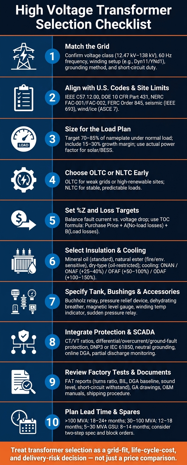
Checklist for Selecting High Voltage Transformers for Grids
A transformer spec can shape your project for years. If I get the voltage, impedance, cooling, protection, or test scope wrong, I can face utility delays, a 12–24+ month replacement wait, and higher lifetime cost from energy losses.
Here’s the short version: before I send an RFQ, I need to lock down the POI voltage, winding connection, grounding, fault-duty limits, MVA and tap-changer plan, loss targets, insulation and cooling, protection/SCADA points, and factory/site testing. I also need to check site limits like ambient temperature, altitude above 3,300 ft (1,000 m), access for delivery, and coating needs for coastal or industrial yards.
If I want a clean buying checklist, these are the points that matter most:
- Match the grid first: voltage class, 60 Hz, winding setup, grounding method, and short-circuit duty
- Check U.S. rules and utility specs: IEEE, DOE, NERC, FERC, seismic, wind, and site conditions
- Size for the load plan: use actual power factor and leave room for growth
- Choose OLTC or NLTC early: weak grids and high-renewable sites often need voltage control under load
- Set %Z and loss targets carefully: fault current, voltage drop, and lifetime cost all depend on this
- Pick insulation and cooling to fit the site: oil type, BIL, ONAN/ONAF/OFAF/ODAF, temperature rise, and noise
- Include the right hardware: relays, breather, level gauge, temperature indication, bushings, and tank details
- Tie it into protection and SCADA: CT/VT data, alarms, trips, grounding, protocol, and physical fit
- Review testing and documents before PO: FAT reports, drawings, O&M manuals, shipping plan, and commissioning checks
- Plan for lead time and spares: large units can take 18–24+ months, so schedule risk is part of the buy
Quick comparison
| Area | What I need to confirm | Why it matters |
|---|---|---|
| Grid match | Voltage, frequency, winding, grounding, fault duty | Utility approval and system fit |
| Ratings | MVA, growth margin, tap changer, %Z | Load handling, voltage control, fault levels |
| Cost | No-load and load losses, TOC | Long-term spend, not just PO price |
| Site fit | Temperature, altitude, seismic, coatings, access | Install limits and service life |
| Transformer build | Insulation medium, BIL, cooling class, accessories | Safety, capacity, upkeep, noise |
| Integration | Protection points, SCADA, bus/cable fit | Relay logic, alarms, field install |
| QA and schedule | Factory tests, documents, lead time, spares | Fewer delays at delivery and startup |
In other words: I should treat transformer selection as a grid-fit, life-cycle-cost, and delivery-risk decision - not just a price comparison.
High Voltage Transformer Selection Checklist for Grid Projects
Assess Grid Interconnection Requirements
Use the POI to lock the transformer interface before you compare design options.
Identify System Voltage and Connection Details
Start with the utility's stated primary and secondary voltage classes. In the U.S., common interconnection voltages run from 12.47 kV to 138 kV.
Before you stack one design against another, work through a short set of checks:
- Match the primary and secondary voltage classes to the utility's interconnection agreement
- Confirm the system frequency is 60 Hz
- Document the winding setup; many step-up applications use Dyn11 or YNd1, where the delta winding helps absorb harmonics and the wye side gives you a grounded neutral
- Confirm the grounding method - solid grounding, HRG, or NGR - as listed in the interconnection requirements
- Verify POI short-circuit duty so %Z limits fault current without nuisance trips
For solar and BESS projects, check whether a K-factor rating is required. Inverter harmonics can cause excessive core heating in a standard transformer.
Once the POI is nailed down, the next step is to check the code rules and site limits that can narrow the design fast.
Align with U.S. Codes, Utility Specs, and Site Limits
Code and site conditions can rule out a design long before pricing does. That’s why it helps to confirm these items early:
- Confirm compliance with IEEE C57.12.00 for general design, IEEE C57.110 for harmonic loading, and DOE 10 CFR Part 431 for federal efficiency standards
- Verify NERC FAC-001/FAC-002 and FERC Order 845 requirements for grid-scale projects
- Confirm the ambient temperature range in both °F and °C, since it affects cooling class selection
- Flag any site altitude above 3,300 ft (1,000 m), which calls for derating of both cooling capacity and dielectric strength
- Document seismic requirements under IEEE 693, wind and ice loading under ASCE 7, and hurricane wind ratings
- Note coastal or industrial sites that may need C4/C5 corrosion-resistant coatings on the tank and bushings
Site limits matter just as much during delivery and install. Check road weight limits, bridge clearances, and crane access before locking the transformer footprint.
sbb-itb-501186b
Define Electrical Ratings and Performance
Once the POI and site boundaries are set, the next job is to lock in the electrical ratings. This step shapes pretty much every design choice that follows.
Confirm MVA Rating, Loading Plan, and Tap Changer Needs
Set the MVA rating based on real power, actual power factor, and expected load growth. For solar and BESS projects, use the inverter’s actual power factor, not a default 0.8 assumption. A common target is 70% to 85% of nameplate under normal load, plus a 15% to 30% growth margin.
Tap changer choice matters too. The difference between an On-Load Tap Changer (OLTC) and a No-Load Tap Changer (NLTC) affects both cost and day-to-day operation.
| Feature | OLTC | NLTC |
|---|---|---|
| Voltage Regulation | Dynamic, adjusts while energized | Manual, requires de-energization |
| Initial Cost | Higher | Lower |
| Best Fit | Weak grids or high-renewable penetration areas | Stable, predictable loads |
If the project connects to a weak grid or a high-renewable system, confirm OLTC needs with the utility.
Verify Impedance, Losses, and Operating Limits
After sizing, set fault-current limits and life-cycle cost targets.
Percent impedance (%Z) affects both fault current and voltage drop. Lower %Z helps voltage regulation, but it also increases fault current. That can push downstream switchgear past its interrupting rating. Higher %Z limits fault current, but it can also lead to voltage sag and equipment trips. That tradeoff is why the fault-current study should be done before this value is locked.
Losses need the same kind of careful look. The purchase price alone usually doesn’t tell the full story. Use the Total Owning Cost (TOC) formula: TOC = Purchase Price + A(No-load losses) + B(Load losses). Here, A and B are the capitalized cost of each loss type over the transformer’s service life. In plain terms, compare bids on life-cycle cost, not just the sticker price.
Set the maximum sound level in dB(A) for sites near homes or other noise-sensitive areas. That limit should be treated as part of the substation placement constraint.
Next, line up insulation, cooling, and mechanical features with these ratings.
Select Insulation, Cooling, and Mechanical Features
Once the electrical ratings are set, the next step is to lock in the insulation, cooling method, and hardware for the site.
Choose the Insulation Medium and Dielectric System
Mineral oil is the standard choice for transmission service. Natural ester fits fire-sensitive or environmentally sensitive sites. Dry-type units make sense only where oil is not allowed.
| Feature | Mineral Oil | Natural Ester | Dry-Type |
|---|---|---|---|
| Grid Use Case | Standard transmission/substation | Renewables, environmentally sensitive sites | Indoor, rooftop, vault, or other oil-restricted locations |
| Fire Risk | Higher (lower flash point) | Lower (high fire point) | Lowest |
| Environmental Profile | Risk of soil/water contamination | Biodegradable, reduced environmental risk | Minimal environmental risk |
| Maintenance | Regular oil testing and DGA | Specialized sampling and handling | No fluid testing |
| Voltage Limit | Up to 1,200 kV | Typically up to 220 kV | Usually ≤ 36 kV |
There’s a simple way to think about this: mineral oil is the default, natural ester is the safer fit where fire or spill risk matters more, and dry-type is the niche option for places where liquid insulation is off the table.
Match BIL to the voltage class, and apply altitude derating to insulation and bushings above 3,300 feet.
Next, line up the cooling class with the load and the site temperature.
Define Cooling Class and Temperature Rise Limits
ONAN is the simplest setup. ONAF can add 25% to 40% more capacity, while OFAF and ODAF push capacity higher on large units.
| Cooling Class | Capacity Boost | Maintenance Burden | Noise Level |
|---|---|---|---|
| ONAN | Base rating | Lowest (passive) | Lowest |
| ONAF | +25–40% | Moderate (fan motors) | Moderate |
| OFAF | +50–100% | High (pumps + fans) | High |
| ODAF | +100–150% | Very high (complex controls) | High |
In plain terms, more cooling usually means more output, but it also brings more parts, more noise, and more upkeep. That tradeoff matters. A remote yard may tolerate extra fan and pump systems. A tight urban site may not.
For critical grid nodes, specify redundant fan or pump groups so a single component failure does not force a derating event. Also set top-oil and winding temperature rise limits to match the load profile, ambient conditions, elevation, and contingency duty.
Specify Tank, Bushings, and Required Accessories
The tank style, bushings, and accessories should line up with the cooling and protection scheme. Confirm whether the unit uses a conservator tank or a hermetically sealed tank, because that choice drives which breathers and gas relays are needed.
The table below covers the core accessories that should be considered in a grid transformer specification:
| Accessory | Function | Requirement |
|---|---|---|
| Buchholz Relay | Detects internal gas or arcing | Mandatory for conservator-type oil units |
| Pressure Relief Device | Vents internal pressure spikes | Mandatory for all liquid-filled units |
| Dehydrating Breather | Removes moisture from air intake | Silica gel or self-regenerating type |
| Magnetic Level Gauge | Monitors oil volume | Required with low-level alarm contacts |
| Winding Temp Indicator | Monitors thermal stress | Required for cooling control and tripping |
| Sudden Pressure Relay | Rapid internal fault detection | Recommended for large power transformers |
These parts can look like small details on paper, but they shape day-to-day operation. A missing relay or the wrong breather type can turn routine service into a headache.
For coastal sites, specify polymer-composite bushings and C5 coatings to reduce salt tracking and corrosion. Also verify that the tank includes lifting lugs, jacking pads, and earthing pads in accessible spots so installation and routine inspection stay simple.
After the mechanical package is fixed, verify protection and SCADA integration.
Verify Protection, Monitoring, and Substation Integration
With the mechanical package locked in, the next job is making sure the transformer can be protected, watched, and installed in the substation without ugly surprises later. The accessory points in the mechanical spec should feed straight into the protection and SCADA design.
Confirm Protective Functions and Monitoring Points
Specify differential, overcurrent, and ground-fault protection. Then make sure CT/VT ratios and accuracy classes line up with the relay requirements. The neutral grounding method also needs to match the grid protection scheme.
Tank alarms, pressure devices, and temperature indicators should tie into the relay logic. It’s also smart to state the maximum V/Hz ratio for overfluxing protection up front. For far-north sites, check whether Geomagnetic Induced Current (GIC) exposure is an issue. If it is, spell out the maximum magnitude and duration the transformer must withstand.
For condition monitoring, add:
- Online DGA
- Moisture monitoring
- Oil level indication
- Partial discharge monitoring
These points help with early fault detection and day-to-day asset health checks.
Check SCADA, Buswork, and Physical Interconnection Fit
Once the relay logic is set, map every alarm, trip, and status point to the utility SCADA system. Confirm the marshalling box gathers accessory wiring correctly, and check that local and remote alarm indications, remote data acquisition, and the communication protocol all line up with the utility SCADA system.
On the physical side, check that bushing terminals and their orientation match the planned bus or cable terminations. Verify that phase spacing and air clearances meet the applicable IEEE requirements. If the site needs a certain enclosure rating, such as NEMA or IP codes, confirm that too. And don’t overlook access: inspection covers and drain/sample valves need to be placed where field crews can actually reach them.
| Integration Check | What to Verify |
|---|---|
| CT/VT Interface | Ratios and accuracy classes match relay requirements for differential, overcurrent, and ground-fault protection |
| Neutral Grounding | Arrangement is solidly grounded, resistance grounded via NGR, reactance grounded, or ungrounded as required by the grid protection scheme |
| SCADA Protocol | DNP3 or IEC 61850 compatibility, with local and remote alarm indications and remote data acquisition |
| Bushing Terminals | Type and orientation match planned bus or cable terminations; phase spacing and air clearances meet applicable IEEE requirements |
| Maintenance Access | Marshalling box, inspection covers, and drain/sample valves are reachable for field crews |
| Surge Arrester Coordination | Ratings cover lightning impulse and switching surge levels |
Review Testing, Documentation, and Procurement Readiness
With protection and SCADA already defined, the next step is simple: check the test record, document set, and delivery plan before issuing the PO. This is where small misses can turn into big delays.
Review Factory Tests, Site Checks, and Compliance Records
Routine factory tests should cover turns ratio, winding resistance, insulation resistance, no-load loss, BIL, chopped-wave impulse, AC withstand, partial discharge, temperature rise, sound level, and short-circuit withstand.
It also helps to set a Dissolved Gas Analysis (DGA) baseline at the factory before the transformer ships. That gives you a clean starting point. When you compare that baseline with commissioning samples, you can spot shipping damage before energization.
Before approving the unit, make sure the documentation package is complete:
| Document | When Required | Purpose |
|---|---|---|
| Certified Test Reports | After FAT | Records actual performance vs. guaranteed values |
| Nameplate Datasheet | Before Manufacturing | Confirms ratings, BIL, and cooling stages |
| General Arrangement (GA) Drawing | Before Detailed Design Review | Confirms dimensions, weights, and terminal positions |
| O&M Manuals | At Delivery | Covers installation, maintenance, and spare parts |
| Packing & Shipping Procedure | Before Shipment | Documents nitrogen fill, shock monitoring, and preservation |
At the site, repeat insulation resistance and turns-ratio checks. Also verify oil quality records, and confirm that fans, pumps, and protection relays work as intended before energizing. This step may feel routine, but it’s often where transit issues first show up.
Confirm Lead Time, Spare Parts, and Sourcing Options
Once the unit is technically cleared, shift your focus to schedule risk and spare-parts support.
Lead times can be long, and they vary a lot by transformer type:
- Units above 100 MVA can take 18 to 24+ months
- Medium power transformers (30 to 100 MVA, 69 to 138 kV) often take 12 to 18 months
- GSU transformers (5 to 30 MVA, 34.5 kV) typically need 8 to 14 months
If the project schedule is tight, a two-step specification can help. In plain terms, you lock a manufacturing slot with a preliminary spec first, then finalize the technical details within 60 days. For jobs with multiple identical units, block orders may improve manufacturing priority. And on multi-unit projects, it makes sense to require locally stocked spares for critical components as part of the contract.
When bids come in, compare total owning cost, not just purchase price. A lower upfront number can look good on paper and still cost more later.
For new or used units, Electrical Trader can help source transformers and related power equipment.
FAQs
How do I choose between OLTC and NLTC?
Choose an OLTC when your grid sees frequent voltage swings or when you’re feeding critical loads that can’t afford downtime. It lets you adjust voltage while the transformer stays energized, and it can handle automatic regulation.
Choose an NLTC when the grid is stable and tap changes only come up once in a while, like during seasonal shifts. It’s simpler and costs less, but you have to de-energize the transformer before changing taps.
What transformer losses matter most over time?
The main losses to look at over a transformer's life are no-load losses, load losses, and auxiliary losses.
- No-load losses happen any time the transformer is energized, even if it isn't serving much load.
- Load losses show up in the windings and go up as current goes up.
- Auxiliary losses come from cooling gear, such as fans.
Looking at these losses by their dollar-per-kilowatt value gives you a better view of total cost of ownership, not just the purchase price. In plain terms, a lower upfront cost can lose its appeal fast if the unit wastes more power year after year.
Which site conditions can force a redesign?
Site conditions can force a design or spec change. The most common trouble spots are extreme temperatures, high altitude, and harsh environments like humidity, salt exposure, or pollution.
For example, installations above 3,300 feet or in temperatures over 104°F may need kVA de-rating or specialized cooling. And some job sites are just tougher on equipment than others. Mining, coastal, and renewable energy locations may call for changes to enclosure protection, corrosion resistance, or mechanical strength.