Medium Voltage Transformers for Offshore Wind Farms
If you want the short answer: offshore wind MV transformers must do three things well - step turbine output from about 690 V–1.2 kV up to 33 kV or 66 kV, survive salt, moisture, and vibration, and stay online because offshore repairs can cost a lot and take days or weeks.
If I strip the topic down to what matters most, it looks like this:
- At the turbine, the transformer moves generator voltage up to the array-cable level.
- At the offshore substation, another transformer steps power up again, often to about 220 kV, for the trip to shore.
- Placement matters: nacelle-mounted, tower-base, and platform-mounted units each have different weight, cooling, and service limits.
- 33 kV vs. 66 kV is a key project choice. For large turbines, 66 kV cuts current, lowers cable losses, and can reduce the number of strings and substation bays.
- Dry-type vs. liquid-filled usually comes down to location: dry-type is common inside turbines, while liquid-filled units are common at the offshore substation.
- Design checks must cover harmonics, short-circuit duty, LVRT, VFTO, insulation class, cooling method, and marine sealing.
- Distance to shore shapes export design: HVAC is common at shorter ranges, while HVDC often makes more sense farther out, especially past about 93–124 miles (150–200 km).
- Life-cycle cost matters more than purchase price, because vessel access, downtime, losses, and replacement logistics can hit hard offshore.
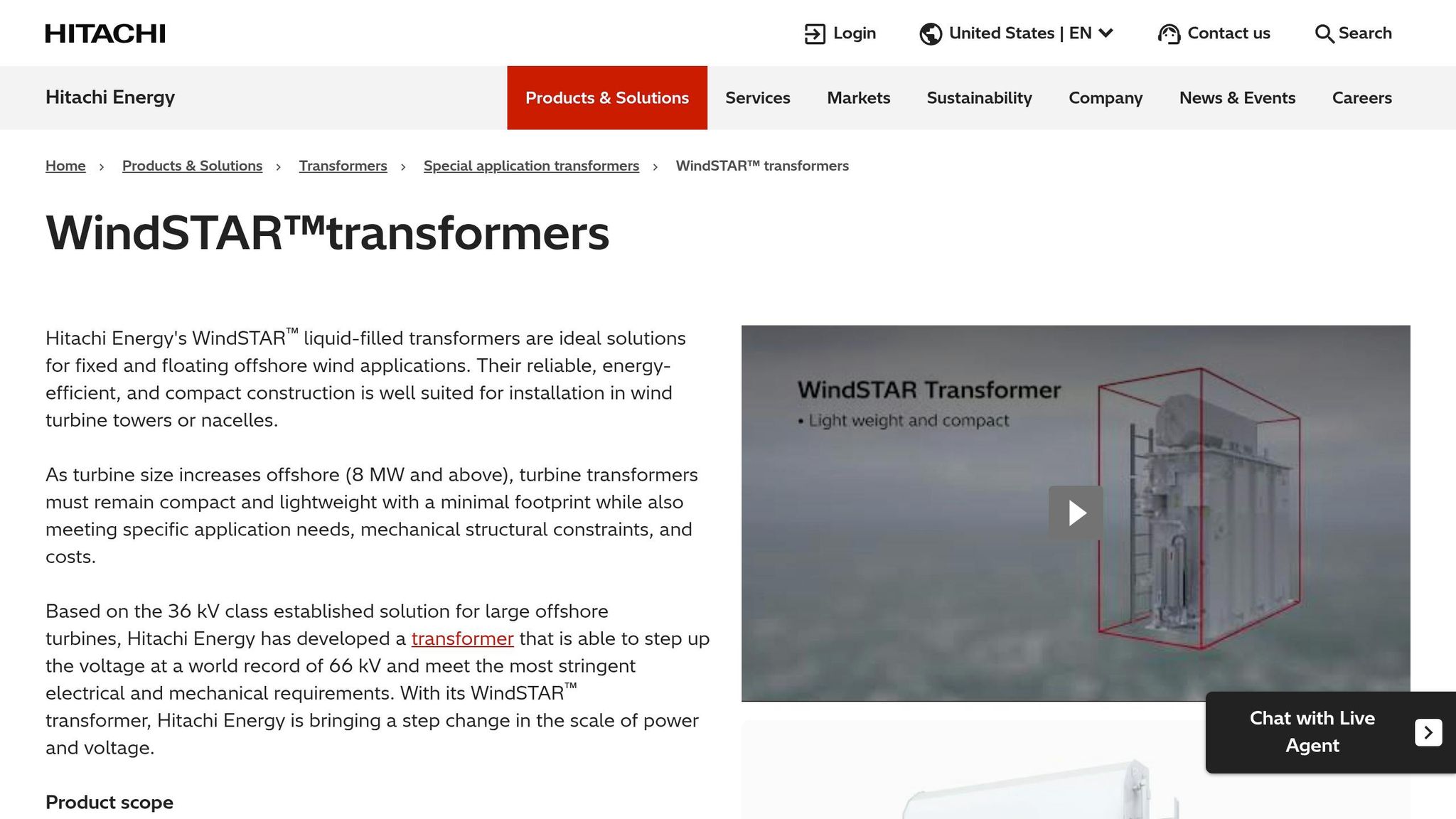
WindSTAR transformers enable the next generation of powerful offshore wind turbines
sbb-itb-501186b
Quick comparison
| Topic | Main point |
|---|---|
| Turbine voltage | Usually 690 V to 1.2 kV |
| Collection voltage | Usually 33 kV or 66 kV |
| Export voltage | Often around 220 kV |
| Common turbine transformer types | Dry-type cast-resin or compact liquid-filled designs |
| Common OSS transformer type | Large liquid-filled power transformer |
| Best use for 33 kV | Smaller turbines and shorter, less dense arrays |
| Best use for 66 kV | 10–20+ MW turbines and larger offshore layouts |
| Main offshore risks | Salt spray, humidity, vibration, hard access, long downtime |
| Key electrical stress points | Harmonics, thermal cycling, faults, VFTO, reactive power |
| Main buying lens | Total ownership cost, not just upfront price |
So if I were choosing an offshore MV transformer, I’d focus first on location, voltage class, cooling, marine sealing, and service access. Everything else follows from those decisions.
Roles and Configurations of MV Transformers in Offshore Wind
Turbine, Collection, and Offshore Substation Transformer Functions
Access limits and harsh offshore conditions push MV transformers into two clear roles: one at the turbine and one at the offshore substation. Inter-array cables link these points across the wind farm.
At the turbine, the MV transformer steps generator output up to 33 kV or 66 kV. At the OSS, larger transformers lift that collection voltage to export level. In practice, these OSS transformers often shape the platform itself. Their rating has a direct effect on platform weight, layout, and cost.
| Stage | Voltage In | Voltage Out | Primary Role |
|---|---|---|---|
| Turbine Transformer | 0.69–3.3 kV | 33–66 kV | Step up generator output to array grid |
| OSS Transformer | 33–66 kV | 132–245 kV | Step up for long-distance export |
Nacelle-Mounted, Tower-Base, and Platform-Mounted Designs Compared
Where the transformer sits changes almost everything: size, weight, cable length, and how hard it is to service.
Nacelle-mounted units are installed at the top of the tower beside the generator. That setup keeps cable runs short, which is a clear plus, but it also adds weight high up on the tower. Because of that, these transformers need to be compact, resistant to vibration, and practical to service during tight offshore access windows.
Tower-base transformers move the unit down to the bottom of the tower, which eases the weight issue. They still step voltage up to 33 kV or 66 kV, but they are easier to access and can be a bit larger. To fit inside the tower, these units often use a slender tank design.
Platform-mounted transformers at the OSS are in a different class. A typical 300 MVA, 230 kV offshore substation transformer weighs about 330 metric tons. Since crews usually reach them by vessel, they need strong cooling systems and marine-rated enclosures.
Winding Configurations and Voltage Regulation Options
Placement also affects winding design and voltage control. The winding type is chosen based on voltage level: layer windings for low voltage, disc windings for medium voltage, and continuous windings for high voltage. Offshore wind transformers also need to deal with converter-generated harmonic currents.
For voltage control, on-load tap changers (OLTCs) adjust output as wind production shifts. Shunt reactors help counter cable reactive power and limit voltage rise. Those operating needs set the stage for the design requirements discussed next.
Design Requirements for Offshore Medium Voltage Transformers
Those placement choices lead to the next hurdle: the transformer has to handle constant electrical cycling, harsh marine conditions, and the fact that maintenance access is often limited.
Electrical Performance Under Variable Load, Harmonics, and Faults
Offshore transformers move back and forth between light load and full load as wind output shifts. That constant cycling puts thermal and mechanical stress on the windings and the clamping structure.
Power electronics inside the turbine add another layer of stress. PWM inverters produce non-sinusoidal currents, so the transformer design needs to control harmonic losses and keep THD low. One common fix is to place grounded electrostatic screens between the primary and secondary windings. These screens filter high-frequency components before they reach the high-voltage side.
VFTO is another serious insulation risk. Switching from vacuum circuit breakers can produce VFTO spikes that hit the insulation system hard. During the design stage, engineers need to check for resonance so those spikes don't get amplified.
Short-circuit strength also matters. Offshore transformers must stay stable during external faults and meet LVRT requirements. To help with that, designers often use copper foil for low-voltage windings and semi-hard enameled flat wire for high-voltage windings.
Electrical stress is only one side of the story. The marine setting shapes the mechanical design just as much.
Marine Durability, Cooling, and Compact Construction
Salt spray, humidity, and vibration call for marine-grade coatings, stainless hardware, and sealed enclosures. In liquid-filled units, hermetically sealed construction is usually favored over standard conservator designs because it keeps moisture and salt out of the tank.
Transformers in nacelles and tower bases need to be compact, resistant to vibration, and light enough for the turbine structure. OSS units also need strong marine sealing, and weight stays a big concern because platform space is tight.
Cooling has to fit both the transformer location and its rating. Smaller units may use ONAN. Higher-rated units may need ONAF. Larger turbines often rely on forced liquid cooling.
Dynamic thermal rating can reduce oversizing and help trim platform weight.
Once the mechanical and thermal setup is defined, protection and compliance become the last big filters.
Protection, Fire Safety, and Standards Compliance
IEC 60076-16 is the main standard for wind turbine step-up transformers up to 72.5 kV. Thermal loading is covered by IEC 60076-7 and IEEE C57.91.
Key protection features include winding temperature sensors and insulation-condition monitoring.
Dry-type cast-resin transformers remove oil fire risk, which makes them a good fit for installations inside turbine towers where suppression systems are hard to maintain. When liquid-filled units are used, ester fluids such as MIDEL 7131 and FR3 offer better fire safety and environmental performance than mineral oil.
These requirements narrow the practical options for voltage class, cooling type, and transformer construction.
How to Select the Right MV Transformer for an Offshore Wind Project
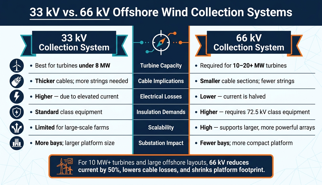
33 kV vs. 66 kV Offshore Wind Collection Systems: Key Differences
Match Transformer Specs to Project Electrical Requirements
Once the electrical, thermal, and marine limits are clear, transformer selection comes down to three main things: rating, insulation, and voltage class. Start by defining the generator voltage, collection voltage, short-circuit duty, harmonic distortion, and LVRT needs before you compare designs.
If the transformer will connect to a PWM inverter, it should have a harmonic-tolerant K rating. That helps it handle non-sinusoidal currents without speeding up insulation aging. VFTO withstand should also be checked early. Offshore cables and vacuum circuit breakers can increase the risk of high transient spikes, and those spikes can damage insulation if the transformer is not built for them.
Grid code duties finish out the electrical checklist. The transformer has to support LVRT, and the design may also need a no-load tap changer (NLTC) or an on-load tap changer (OLTC) for voltage control.
Dry-Type vs. Liquid-Filled and 33 kV vs. 66 kV: Key Tradeoffs
For installation location, the split is pretty clear. Dry-type cast-resin transformers are the default for nacelle and tower-base use because space is tight and spill risk has to stay at zero. Liquid-filled units fit offshore substation platforms better, where thermal performance matters more. So the voltage decision is tied to platform layout and cable design, not just the one-line diagram.
For larger turbines, 66 kV lowers current, cuts cable losses, and reduces the number of array strings.
| Feature | 33 kV System | 66 kV System |
|---|---|---|
| Turbine Capacity | Suited for turbines under 8 MW | Required for 10–20+ MW turbines |
| Cable Implications | Thicker cables; more strings needed | Smaller cable sections; fewer strings |
| Insulation Demands | Standard | Higher; requires 72.5 kV class equipment |
| Electrical Losses | Higher due to elevated current | Lower; current is halved |
| Scalability | Limited for large-scale farms | High; supports larger, more powerful arrays |
| Substation Impact | More bays; larger platform size | Fewer bays; more compact platform |
Total Cost of Ownership, Replacement Access, and Sourcing Options
Don’t stop at purchase price. Look at life-cycle cost, including no-load losses, load losses, maintenance intervals, and how easy it is to get vessel access if the unit has to be replaced.
Dynamic Thermal Rating (DTR) can play a big role here. Instead of sizing transformers around conservative nameplate assumptions, DTR uses actual wind load profiles. In some cases, that can reduce transformer rating by up to 35%, which cuts platform weight and lowers foundation costs. That matters because offshore transformer designs are often built for 40–45 years, while the wind farm itself may only run for 25–30 years. If you oversize the unit, you’re paying for more equipment life and capacity than the project may ever use.
For repowering or decommissioning, Electrical Trader can source new or used transformers. Those sourcing choices can also affect export-system cost and platform layout.
MV Transformers in Offshore Transmission Strategy and Key Takeaways
How MV Transformers Support HVAC and HVDC Export Systems
Once the transformer type and voltage are locked in, the export plan decides how the wind farm gets power back to shore.
The 33 kV or 66 kV collection grid feeds that export system. For projects within about 93 miles (150 km) of shore, HVAC export is usually the go-to option. In that setup, MV transformers step voltage up to around 220 kV at the offshore substation, and power then moves through a subsea cable.
The big issue with long AC cables is reactive power. That means offshore substations need shunt reactors for compensation, which adds weight and extra system complexity.
That same collection voltage also plays a big part in the HVAC-versus-HVDC choice. Once the distance moves past about 93 to 124 miles (150 to 200 km), HVDC export is usually preferred because it cuts transmission losses. MV transformers still step up voltage at a converter platform before AC-to-DC conversion. After that, the DC link avoids most of the reactive power problems that come with long HVAC cables.
Trends Shaping Future Offshore Transformer Specifications
These export limits are driving a few clear spec trends.
66 kV collection systems are becoming the default. When collection voltage doubles, current is cut in half. That trims losses and helps support larger 15–20 MW+ turbines with fewer offshore substations needed.
Digital condition monitoring is becoming standard. Sensors that track top-oil temperature, hot-spot temperature, moisture, and partial discharge give operators a much clearer view of thermal margin. Dynamic thermal rating can reduce oversizing and cut platform weight.
Further offshore, medium-voltage DC (MVDC) collection concepts are under study. These setups use DC/DC converters and medium-frequency transformers at each turbine, which may reduce the need for large offshore platforms.
High-temperature superconducting (HTS) transformers are also under review for offshore substations. Compared with conventional units, HTS designs can reduce the weight-to-capacity ratio by 32.15%, which matters when platform space and lifting limits are tight.
Conclusion: Core Selection Points for Offshore Wind Projects
Offshore transformer selection comes down to site location, electrical duty, marine exposure, and life-cycle cost. A nacelle-mounted unit faces a very different set of limits than a substation transformer on a fixed-bottom platform.
Teams should work through voltage class, harmonic tolerance, fault withstand, and cooling method early in the process. Marine exposure matters too. Salt mist, humidity, and vibration can wear down a transformer that was not built for offshore duty. It also helps to think ahead about replacement access and vessel logistics when weighing one option against another.
Electrical Trader can help teams source transformers that fit project, access, and budget constraints.
FAQs
How do I choose between 33 kV and 66 kV?
Choose based mainly on your offshore wind farm’s size and performance needs.
33 kV has long been the standard. The main reason is simple: the equipment is easy to source and fits inside turbine towers.
66 kV is becoming the go-to pick for larger wind farms. It can carry more power, cut the number of switchgear bays, and may lower total life-cycle costs.
Which transformer type is best offshore?
For offshore wind projects, dry-type resin-cast transformers are usually the best fit inside turbine nacelles or towers. They’re compact, fire-safe, resist moisture well, and need very little maintenance.
For larger offshore substations, oil-immersed transformers are also common. In many cases, they use biodegradable ester fluids to cut the risk of harm if a leak happens. Newer designs are also shifting from 33 kV to 66 kV to improve efficiency and save space on the platform.
What matters most besides purchase price?
Beyond purchase price, the factors that matter most are reliability, the ability to handle harsh conditions, and plain physical limits. Offshore transformers have to keep working in tough marine settings, where corrosion, salt, and heavy mechanical vibration are part of the job.
Weight, footprint, maintenance demands, and performance under load swings, harmonics, and efficiency requirements also shape long-term, stable grid transmission. Electrical Trader offers a centralized marketplace for sourcing these specialized components.