
Checklist for Electrical Skill Assessments
When preparing for an electrical skills assessment, the focus is on practical, hands-on capabilities rather than written exams. This checklist ensures you’re ready to demonstrate key skills like circuit isolation, wiring installation, fault identification, and adherence to safety protocols. Here’s what to know upfront:
- Preparation Matters: Align your documentation, tools, and references to industry standards (e.g., NEC, OSHA). Start gathering work logs and certifications (OSHA, First Aid/CPR) at least 4–8 weeks in advance.
- Safety First: Proper use of PPE, following lockout/tagout (LOTO) procedures, and maintaining a safe workspace are critical for success.
- Technical Skills: Be ready to size conductors, apply grounding and bonding techniques, and install/test devices like GFCIs and AFCIs.
- Testing & Troubleshooting: Show proficiency with tools like multifunction testers, follow systematic fault diagnosis, and verify repairs meet compliance.
This checklist helps candidates and assessors streamline the process, ensuring evaluations are thorough and meet current industry expectations.
Pre-Assessment Preparation Checklist
Careful preparation is key to ensuring a seamless assessment process. Before diving in, double-check that all standards, qualifications, and documentation are properly aligned.
Regulatory Compliance and References
Every assessment should align with the relevant codes. In the U.S., this typically includes the National Electrical Code (NEC/NFPA 70), NFPA 70E for workplace electrical safety, and applicable OSHA standards. Verify the specific NEC edition adopted by the Authority Having Jurisdiction (AHJ) - whether it's 2020, 2023, or 2026 - to avoid any missteps during testing.
In addition to national codes, assessors need to review equipment manufacturer specifications and any site-specific safety protocols. For assessments involving power generation, transmission, or distribution equipment, reference NETA's Acceptance Testing Specifications (ATS) or Maintenance Testing Specifications (MTS) as necessary.
Candidate Prerequisites and Training
Candidates must come prepared with well-organized documentation. For journeyman-level assessments, this typically includes:
- 8,000+ hours of documented supervised work experience
- Proof of completed apprenticeship training, often encompassing 144–800 hours of classroom instruction
- Valid OSHA compliance training and First Aid/CPR certification
"Whether you're studying for an electrical license, preparing for an inspector certification, or upgrading your skills as a working electrician, NEC knowledge is non-negotiable." - Dr. Lisa Patel, Certified Test Prep Specialist
It's a good idea to start gathering signed work experience logs and transcripts at least 4 to 8 weeks before the assessment date, as the review process can take longer than anticipated.
Once prerequisites and references are squared away, attention should shift to organizing the tools and documentation needed for the assessment.
Assessment Tools and Documentation
Having a well-organized assessment packet can save time and minimize errors. Assessors should prepare risk assessment documents and Schedules of Test Results, while candidates should bring tool calibration records and any required work instructions or diagrams relevant to the assessment.
| Document/Tool | Purpose |
|---|---|
| One-line power diagrams + Bill of Materials (BOM) | Provides installation reference for assessors and candidates |
| Assessment forms | Captures risk assessments and test results consistently |
| Tool calibration records | Verifies that testing equipment meets accuracy requirements |
| Circuit directories and panel schedules | Confirms labeling compliance (NEC Article 408.4) |
| Approved voltage testers (proved working) | Required for safe live-circuit verification |
To streamline the process, create a "proof bundle" - a single, consolidated folder containing the one-line diagram, BOM, and key component datasheets. This can help address assessor questions more efficiently.
sbb-itb-501186b
Safety Practices and PPE Checklist
8-Step Lockout/Tagout (LOTO) Process for Electrical Safety Assessments
When it comes to safety on the job, a candidate's ability to handle risks effectively is paramount. This section outlines what assessors should observe regarding the proper use of personal protective equipment (PPE), lockout/tagout (LOTO) procedures, and maintaining control over the work environment. These elements are key to evaluating practical skills during compliance assessments.
Proper Use of Personal Protective Equipment (PPE)
Candidates must demonstrate the ability to inspect and use PPE correctly, ensuring all items are rated for the specific nominal voltage of the equipment they are working on. Essential PPE includes voltage-rated gloves, arc-rated clothing, and insulated tools. Assessors should confirm that these items are in good condition and meet the required ratings.
It’s also critical that candidates remove conductive items - such as rings, watches, key chains, and metal-buckled belts - before approaching energized equipment. Additionally, any portable ladder used near live parts must have nonconductive siderails. For circuits exceeding 600 volts, candidates must verify the proper operation of test equipment both before and after testing.
Once PPE has been checked, assessors should observe the candidate's adherence to established LOTO procedures.
Lockout/Tagout and Hazard Recognition
LOTO is a fundamental skill in electrical work. OSHA emphasizes this with the following directive:
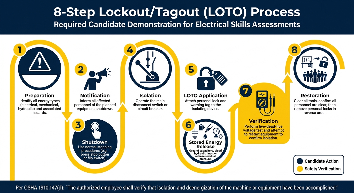
"The authorized employee shall verify that isolation and deenergization of the machine or equipment have been accomplished." - OSHA 1910.147(d)
Candidates are expected to follow an eight-step LOTO process. This includes identifying energy sources, notifying personnel, securing lockout devices, and verifying isolation using the live-dead-live method. The method involves testing a known live source, the deenergized circuit, and the live source again to confirm that the test equipment is functioning properly.
Assessors should also evaluate the candidate's ability to identify arc flash boundaries and incident energy levels, using information from equipment labels or one-line diagrams. Arc flashes can reach staggering temperatures of up to 35,000°F - four times hotter than the surface of the sun - and arc blasts can create pressure waves exceeding 2,000 pounds per square foot.
| LOTO Step | Candidate Action to Demonstrate |
|---|---|
| 1. Preparation | Identify energy types (e.g., electrical, mechanical) and associated hazards |
| 2. Notification | Inform affected personnel of the shutdown |
| 3. Shutdown | Use normal stopping procedures, such as pressing a stop button |
| 4. Isolation | Operate the main disconnect or breaker |
| 5. LOTO Application | Attach personal lock and tag to the isolating device |
| 6. Stored Energy | Ground capacitors or release residual pressure |
| 7. Verification | Perform a live-dead-live voltage test and attempt to start the equipment |
| 8. Restoration | Clear tools, ensure personnel are safe, and remove personal locks |
Maintaining a Safe Work Environment
After confirming PPE and LOTO compliance, assessors should focus on how candidates manage the work area. Maintaining control over the environment is a critical safety measure. Proper lighting is essential to avoid unintentional contact with energized parts. Any instance of working without clear visibility should be flagged.
Candidates must also adhere to OSHA's clearance requirements from live parts, such as maintaining a 2-foot clearance for voltages over 2 kV and a 3.5-foot clearance for voltages above 37 kV. During high-voltage or high-power testing, a test observer should always be present to deenergize the circuit immediately if necessary.
Finally, candidates should conduct a quick risk assessment before starting any task. This involves identifying potential hazards, understanding who might be affected, and taking appropriate precautions. This step reflects professional standards and demonstrates a candidate’s readiness for real-world scenarios.
Key Installation and Wiring Skills Checklist
Building on safety protocols and LOTO procedures, this section focuses on evaluating technical installation and wiring skills. Here, candidates showcase their ability to apply code knowledge to real-world installations that meet compliance standards.
Conductor and Wiring Practices
Proper conductor selection is a critical part of practical assessments. Candidates must size conductors based on actual ampacity, accounting for ambient temperature and bundling adjustments, as outlined in NEC Table 310.16.
Assessors need to ensure candidates avoid errors such as using the 90°C column incorrectly. According to NEC 110.14(C), conductors must align with the lowest terminal temperature rating. For instance, if a breaker is rated at 60°C, the 60°C column must be used.
"The insulation temperature rating of a conductor must be limited to an operating temperature that prevents damage to the conductor's insulation." - Mike Holt
Other key practices to verify include:
- Leaving at least 6 inches of free conductor at outlets or junction boxes.
- Using correct color coding (e.g., white or gray for neutrals, green or bare for equipment grounding conductors).
- Sealing raceways that pass between temperature zones to prevent condensation.
Ampacity adjustments for conductors in raceways are also essential, as shown below:
| Number of Conductors in Raceway | Ampacity Adjustment Factor |
|---|---|
| 4–6 | 80% |
| 7–9 | 70% |
| 10–20 | 50% |
Once conductor selection is verified, assessors should evaluate grounding, bonding, and overcurrent protection to ensure compliance with NEC standards.
Grounding, Bonding, and Overcurrent Protection
The next step is assessing candidates' ability to correctly implement grounding, bonding, and overcurrent protection. These elements are essential for safety and system reliability:
- Grounding provides a reference voltage and a path for lightning or static discharge.
- Bonding ensures metallic parts are connected to create a low-impedance fault-current path, enabling overcurrent protective devices (OCPDs) to trip effectively.
"The grounding electrode and earth route is a high impedance circuit and does not meaningfully contribute to clearing a fault compared to equipment grounding conductors and properly routed grounded service conductors." - NTT Training
Key points to assess include:
- Ensuring the main bonding jumper (MBJ) is installed only at the service disconnect. Bonding neutral to ground at a subpanel creates parallel neutral current paths, which is a common error.
- Using NEC Table 250.66 to size grounding electrode conductors (based on service conductor size) and NEC Table 250.122 for equipment grounding conductors (based on OCPD rating). These are distinct tables with different inputs.
- Matching OCPD ratings to conductor ampacity per NEC 240.4. For example, 14 AWG copper is limited to 15A, 12 AWG to 20A, and 10 AWG to 30A. Oversized breakers for a given wire size should be flagged, as this is a common inspection failure.
Special Locations and Device Testing
In addition to standard wiring practices, candidates must demonstrate the ability to handle specialized installations. Wet, damp, or hazardous locations require specific wiring methods and appropriately rated devices, which candidates should apply correctly during assessments.
Candidates are also expected to install and test GFCI and AFCI devices to confirm proper operation. Untested devices should be treated as failures. For aluminum conductors, candidates must ensure the use of AA-8000 series alloy with AL-rated termination devices and apply anti-oxidant compounds. Standard copper termination practices are not suitable in these cases.
Testing, Troubleshooting, and Verification Checklist
Once candidates have demonstrated their installation and wiring skills, the next step is proving their ability to test, troubleshoot, and verify that systems meet required standards.
Basic and Advanced Testing Skills
Candidates need to show proficiency with their testing tools, especially the multifunction tester (MFT). This device is essential for performing various tests, including continuity, insulation resistance, earth fault loop impedance, prospective fault current, and RCD performance.
Before conducting live tests, candidates must adhere to the prove-test-prove method. This involves using a GS38-compliant two-pole voltage indicator to confirm the circuit is de-energized, completing the required tasks, and re-checking to ensure the circuit remains dead before re-energizing.
"Safe isolation is not optional - it is a mandatory procedure that must be followed every time you work on an electrical circuit." - M. Davies, Electrical Engineering Instructor, Total Skills UK
Insulation resistance testing is another crucial step. Circuits in good condition should show readings of at least 200 megohms when tested at 500V DC. If the reading drops below 1.0 megohm, the issue must be flagged immediately. Additionally, all testing equipment should have been calibrated by an accredited lab within the past 12 months.
Once basic testing is complete, candidates must move on to diagnosing faults effectively.
System Performance and Fault Diagnosis
A structured approach to fault diagnosis is essential. Assessors should evaluate candidates on their ability to follow a 6-step process: gather information, perform a visual inspection, check basic causes, test and measure, interpret results, and verify repairs.
"A systematic approach follows a logical sequence: gathering information, inspecting, testing, interpreting results, and verifying the repair." - M. Davies, Electrical Engineering Instructor, Total Skills UK
The first step is always a visual inspection. Scorch marks, loose connections, or damaged insulation are often visible signs of trouble. For harder-to-detect issues, the half-split method is a reliable strategy. By testing at the circuit's midpoint, this method quickly narrows down the fault's location. On a ring final circuit, it typically identifies the problem within three to five splits.
Candidates must also differentiate between various fault types - open circuits, short circuits (line-to-neutral), earth faults, and high-resistance joints. Each type produces unique test readings and requires specific corrective actions. Repairs are not considered complete until the original fault test is repeated, and the results confirm compliance.
Once the fault is resolved, the next step is sourcing the right replacement components.
Sourcing Compliant Components During Assessment
When replacing faulty parts, candidates must ensure the new components align with the original system's specifications and meet all relevant codes. Resources like Electrical Trader provide an extensive inventory of new and used components that comply with these requirements.
Conclusion: Key Takeaways for Running Effective Assessments
A well-structured checklist can be the difference between passing and failing. With the AM2's pass rate hovering around 70–75%, preparation often determines success. Common mistakes, like incomplete paperwork, inaccurate test readings, or unsafe isolation practices, can be avoided by following a clear framework.
This approach has earned praise from industry professionals.
"The AM2 has been the industry standard since it was introduced by the JIB to ensure that every qualified electrician can demonstrate practical skills under controlled conditions - not just classroom knowledge." - R. Thompson, Senior Electrical Assessor, Total Skills UK
The checklist doesn’t just help candidates - it also streamlines the process for assessors. It ensures all necessary documentation, techniques, and materials align with industry standards. For candidates, it eliminates uncertainty. Resources like the NET Readiness for Assessment Checklist and the TESP Skill Scan highlight areas for improvement before investing in an assessment that can cost around $1,200 plus applicable taxes.
Covering everything from preparation and safety gear to installation and testing, the checklist framework helps candidates build their skills step by step. Practicing under realistic, timed conditions using this method strengthens their abilities and boosts confidence ahead of assessment day.
Whether you're an assessor aiming to standardize evaluations or a candidate working toward certification, using a checklist consistently turns preparation into reliable, measurable competence.
FAQs
What should I bring to a hands-on electrical skills assessment?
For most practical electrical assessments, such as the AM2, you generally won’t need to bring your own tools. Testing centers typically supply calibrated instruments, tools, and materials necessary for the tasks. However, it’s always a good idea to confirm the specific rules with your testing center, as some may restrict personal items like notepads. If you're looking for electrical components and equipment for your work outside of assessments, Electrical Trader has a wide range of options to support your professional needs.
How do I prove a circuit is safe to work on during the assessment?
To ensure a circuit is safe to work on, follow a safe isolation procedure carefully:
- Confirm the circuit is fully isolated and locked out by disconnecting all energy sources.
- Use a reliable two-pole voltage indicator (avoid non-contact testers) to check for the absence of voltage.
- Test the voltage indicator on a known live source both before and after checking the circuit to confirm it’s functioning correctly.
- Check all possible conductor combinations - Line-Line, Line-Neutral, Line-Earth, and Neutral-Earth - to verify there’s no voltage present.
This process ensures the circuit is completely de-energized and safe for work.
What test readings or mistakes most often cause failures?
Assessment failures often stem from a mix of documentation errors and technical oversights. On the documentation side, missing test results or unsigned forms are common culprits. These small administrative mistakes can have a big impact.
On the technical side, frequent errors include:
- Recording incorrect Zs values
- Skipping null tests for leads
- Testing in the wrong sequence
- Failing to isolate circuits properly
Additional problems arise when sensitive equipment is left connected during insulation resistance tests or when polarity checks are overlooked. Measuring Ze without accounting for parallel paths can also lead to inaccurate results. Lastly, poor time management can amplify these issues, leaving tasks incomplete or rushed.


