




Smart Grid Equipment for DER Integration
DER growth is moving fast: the DOE expects 262 GW of added DER and demand flexibility from 2023 to 2027. If I’m buying or specifying gear for a U.S. DER project, I need to check seven things first: breakers, relays, reclosers and switches, meters, transformers, gateways/RTUs, and control panels.
Here’s the short version:
- At the PCC, I need the right breaker, relay, and revenue meter
- On feeders, I need reclosers, sectionalizers, load-break switches, and line sensors
- Between voltage levels, I need transformers that can handle bidirectional power flow
- For site visibility and utility comms, I need gateways, RTUs, and time sync
- For local control, I need UL 508A control panels with room for added I/O
- For approval, I need to match IEEE 1547-2018, utility rules, fault duty, CT/VT ratios, protocol support, and enclosure ratings
A few points stand out right away:
- Power can now flow back toward the substation, not just to the load
- That changes protection coordination, reclosing, metering, and voltage control
- Used gear can save time, but I’d still want test reports, nameplate checks, and documentation
- Location matters: indoor LV panels, MV switchgear, pad-mount gear, and feeder devices do not have the same voltage, enclosure, or communications needs
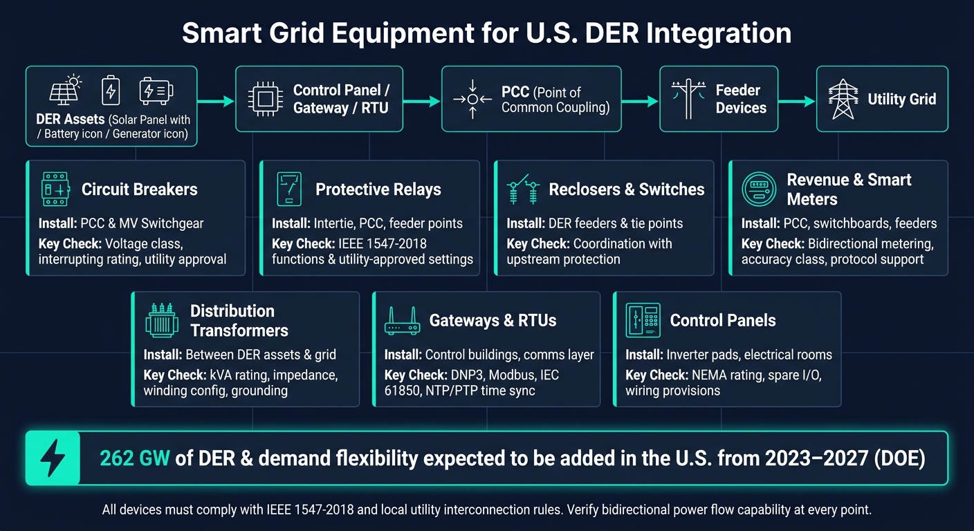
Smart Grid Equipment for DER Integration: 7 Key Device Types at a Glance
Quick Comparison
| Equipment | Main job | Common install point | What I’d check first |
|---|---|---|---|
| Circuit breakers | Fault clearing and isolation | PCC, MV switchgear, service entrance | Voltage class, continuous current, interrupting rating |
| Protective relays | Trip logic and abnormal condition detection | PCC, intertie, switchgear | IEEE 1547 functions, utility settings, directional elements |
| Reclosers / switches | Feeder fault clearing or section isolation | Feeders, tie points, DER taps | Reclose coordination, transfer trip needs, voltage/current rating |
| Revenue / smart meters | Billing and interval data | PCC, switchboards, panels | Bidirectional metering, accuracy class, protocol support |
| Transformers | Voltage step-up/step-down | Service points, buildings, substations | kVA, impedance, grounding, reverse-flow thermal limits |
| Gateways / RTUs | Data collection and protocol conversion | Control cabinets, control buildings | DNP3, Modbus, IEC 61850, NTP/SNTP/PTP support |
| Control panels | Local automation and dispatch | Electrical rooms, inverter pads | NEMA rating, spare I/O, panel space, wiring room |
Bottom line: if I want a DER site to pass utility review and run safely, I start at the PCC, work outward, and verify that every device is rated, coordinated, and able to handle two-way power flow.
sbb-itb-501186b
Protection and Switching Equipment
DER backfeed changes fault coordination at the PCC and across the feeder. That shifts the sizing and settings work too. In most cases, the first devices to review are the breaker and relay at the PCC, then the feeder automation devices farther out on the line. Settings that made sense on a one-way feeder may no longer work once power can flow in both directions. The goal is simple: clear faults selectively without tripping DER when it should stay online.
Circuit Breakers at the PCC and in Medium-Voltage Switchgear
At the PCC, the circuit breaker is the main isolation and fault-clearing device between the customer’s DER and the utility distribution system. The breaker itself depends on protective relays or electronic trip units for sensing and trip logic, so selection usually comes down to three basics: system voltage class, continuous current, and interrupting rating. PCC breakers are commonly installed in medium-voltage switchgear or used as stand-alone interconnection devices.
The breaker also needs the right relay or trip unit behind it. That protection should cover overcurrent, ground fault, voltage and frequency functions, plus directional overcurrent for reverse power flow.
Utilities may also ask for synchronism-check relays or transfer-trip inputs at the PCC to deal with reclosing and anti-islanding risk. Intertie relays, sometimes called interconnection monitor relays, can supervise the PCC breaker and connect into utility control schemes.
Move farther down the feeder, and coordination depends on reclosers and sectionalizing devices.
Reclosers, Sectionalizers, and Load-Break Switches on DER Feeders
A recloser opens when it sees a fault, waits through a set dead time, and then recloses. If the fault stays on the line, the device makes several attempts and then locks out on a permanent fault.
With DER on the feeder, that timing has to line up with anti-islanding behavior. IEEE 1547-2018 requires DER to detect islanding and disconnect within 2 seconds of feeder separation. Some utilities also require reclose blocking or direct transfer trip for larger DER projects.
Sectionalizers are installed downstream of breakers or reclosers. They count upstream fault-clearing operations and open during the de-energized interval. They do not interrupt fault current on their own. Load-break switches are switching and isolation devices. They can make and break load current, usually up to about 600 A, but they are not rated to interrupt fault current. Used together, these devices split long feeders into smaller sections and reduce how much of the line is affected by a fault.
Protective Relays and Intertie Controls
Relays provide the sensing and logic for breaker and recloser operation. In DER interconnections, common functions include phase and ground overcurrent, directional overcurrent, over/undervoltage, over/underfrequency, anti-islanding, reverse power, breaker failure, and synchronism-check where reclosing is part of the scheme.
Utility guidance often starts with the default trip settings in IEEE 1547-2018, but local interconnection rules determine the final values.
At the PCC, the device should be set wider than the DER ride-through window so backup protection does not operate first.
The table below compares each device by function, location, and DER use:
| Device | Primary Function | Typical Location | DER-Specific Use |
|---|---|---|---|
| Circuit breaker | Interrupts fault current and isolates equipment | PCC, switchgear lineups, service entrance | Main disconnect for DER interconnection; must match interrupting rating to site fault current |
| Recloser | Clears temporary faults and automatically recloses | Distribution feeders, overhead lines, PCC | Feeder automation; may require reclose blocking or direct transfer trip with DER present |
| Sectionalizer / load-break switch | Segments feeders and isolates faulted sections | Mid-feeder, DER taps, tie points | Creates smaller line sections; relies on upstream devices for fault interruption |
| Protective relay | Detects abnormal conditions and issues trip commands | PCC, switchgear, control panels | Overcurrent, voltage, frequency, anti-islanding, directional, and breaker failure logic |
These devices only work as intended when the metering and control hardware is right, which the next section covers.
Metering, Transformers, and Power Conversion Support
After protection and switching are in place, metering and transformers help confirm how energy is moving and help keep voltage in check when DERs send power both ways.
Smart Meters, Revenue Meters, and Line Sensors
Once trip settings and switching are set, metering shows what DERs are doing to site load, export levels, and feeder conditions.
At the PCC, utilities usually want revenue-grade meters for import/export billing, net metering, and interconnection checks. Many rely on 15-minute or hourly interval data, along with utility telemetry.
Inside the facility, submetering at switchboards and critical panels helps track:
- Peak demand
- Power factor
- Inverter harmonics
That data supports load studies and day-to-day performance checks.
Line sensors, mounted on poles or placed in feeder cabinets, measure voltage, current, and flow direction. That makes it easier to spot reverse power flow, faults, and local loading issues before they turn into a bigger headache.
Distribution and Substation Transformers for DER Interconnection
Once you can see the flow, transformers become the main lever for voltage control across the DER interconnection.
They sit at each voltage boundary. Step-up transformers move inverter output up to feeder voltage, while step-down transformers serve loads and inverter-connected equipment.
Reverse power flow is one of the big reasons utilities take a close look at transformers before approving interconnection. They review thermal loading, losses, and protection settings to make sure the unit can handle power moving upstream instead of just downstream.
On-load tap changers (OLTCs) on substation transformers matter even more in DER-heavy areas, where feeder voltage can swing with DER output. In practice, different transformer types fit different jobs:
- Pad-mounted transformers work well for underground-fed sites
- Dry-type transformers fit indoor installations
- Substation transformers handle feeder voltage regulation
Where to Source Retrofit and Replacement Equipment
DER retrofits and capacity expansions often call for transformers, meters, breakers, and switchgear that match existing infrastructure and utility interconnection rules. Electrical Trader supplies new and used power distribution equipment, including transformers, medium-voltage breakers, and revenue meters.
If you're buying used gear, don't just glance at the label and hope for the best. Check nameplate ratings, test reports, tap ranges, and OLTC settings to make sure the equipment is fit for bidirectional flow.
The table below sums up where each device is usually installed and what to check before buying:
| Equipment | Function | Typical Installation Point | Key Buying Considerations |
|---|---|---|---|
| Revenue-grade meter | Billing, NEM compliance, import/export measurement | PCC | Interval data capability, bidirectional measurement, utility protocol support |
| Smart meter / sub-meter | Demand tracking, power quality, load study data | Main switchboard, critical panels | Harmonic monitoring, interval logging, communication protocol support |
| Line sensor | Feeder voltage/current monitoring, fault detection, reverse flow detection | Distribution feeders, laterals, DER taps | Measurement accuracy, outdoor rating, DMS/ADMS integration, sync capability |
| Pad-mounted transformer | Voltage transformation for underground-fed DER sites | Commercial/industrial service points | kVA rating, impedance, tap range, thermal limits for reverse power |
| Dry-type transformer | Indoor voltage transformation and isolation | Buildings, data centers, indoor battery/solar systems | Fire rating, voltage class, inverter compatibility |
| Substation transformer with OLTC | Feeder voltage regulation under bidirectional flow | Distribution substations | OLTC reverse-flow compatibility, tap range, firmware version, thermal study documentation |
Gateways, RTUs, and Control Panels
With protection and metering set, the next layer is communications and control.
Gateways and RTUs for Protocol Conversion and Data Collection
After protection and metering are in place, the communications layer makes the DER site visible to SCADA and DERMS. Gateways and RTUs gather data from mixed-vendor field equipment and send it upstream in a standard format.
In the U.S., DNP3 is still the default utility protocol for distribution automation. But field devices often speak Modbus RTU/TCP, proprietary inverter protocols, or IEC 61850. That’s where a gateway comes in. It sits between those device-level protocols and the utility system, collecting data on one side and presenting a clean DNP3 interface to SCADA or DERMS on the other.
This setup works well when older meters or relays need to live beside newer DER assets. Instead of ripping out legacy gear, the gateway adds IP connectivity and helps the whole site speak the same language.
RTUs and gateways use NTP, SNTP, or IEEE 1588 PTP to align event logs.
The right choice depends on where the device sits in the system:
- Use an RTU when hardwired I/O and utility-grade durability matter most.
- Use a gateway when protocol conversion and mixed-vendor integration matter most.
In many U.S. DER projects, both show up in the same design. The RTU acts as the SCADA endpoint, while a gateway inside the control panel handles protocol conversion for inverters, meters, and PLCs. That data path then feeds the control panel, where site commands are carried out.
Control Panels for Inverters, Switchgear, and Site Automation
Once data reaches the site controller, the control panel turns it into action: trips, starts, alarms, and dispatch commands.
A DER control panel brings several functions into one enclosure. It usually includes protection, metering, PLC/HMI control, backup power, and communications hardware. Each part has a clear job. Relays trip breakers based on protection settings. The PLC manages sequences like generator start/stop, islanding transitions, and load shedding. The HMI shows local alarms and DER status. The gateway passes data and commands to SCADA and DERMS.
Panels are commonly built to UL 508A, with NEMA enclosure ratings chosen for the installation environment.
Where the panel goes depends on the project. Utility-scale plants often place panels in control buildings or on inverter pads. C&I microgrids usually use electrical rooms. Industrial sites often tie these panels into plant SCADA or DCS.
It’s smart to size panels with spare I/O and communications ports. DER projects have a habit of growing over time, and running out of panel capacity can become a headache fast. Standard point naming and data models also make future DERMS integration much easier.
How to Select Equipment for U.S. DER Projects
Start with the serving utility's DER technical specification manual and approved device list. That's usually the fastest way to narrow the field. Most utilities line up with IEEE 1547-2018 and spell out which relay models, breaker ratings, and meter classes they accept. Use those utility rules to screen every device, starting at the PCC and moving outward.
Next, review the one-line from the PCC outward. At the PCC, match the voltage class and interrupting rating to the utility fault study. That includes contribution from the inverter, battery, and generator. On feeders, reclosers need to coordinate with upstream protection so the DER clears faults without interfering with reclosing. For transformers, check impedance, winding configuration, grounding, and harmonic tolerance against the inverter-based load.
Then look at the site itself. Electrical fit isn't enough if the gear can't handle the setting. Outdoor switchgear, reclosers, and control panels usually need NEMA 3R or 4/4X. Indoor gear can use NEMA 1. At coastal or industrial sites, corrosion-resistant finishes matter. Rooftops and containers can run hot, so factor in thermal derating and ventilation from the start.
Cost and timing matter just as much as nameplate ratings. Custom medium-voltage switchgear and specialty transformers can come with lead times of several months. Ordering early, based on preliminary approved designs, can help keep the project on schedule. When supply is tight, used or surplus equipment may cut lead time. Electrical Trader carries new and used breakers, transformers, and power distribution gear for retrofit or replacement work. If used equipment is part of the plan, it should go through dielectric testing, primary injection, and a documentation review before installation. That helps confirm the gear still meets current ratings and code requirements.
Key Takeaways by Equipment Type and Installation Point
The table below cuts the selection process down to the factors that usually decide approval and installation.
| Equipment Type | Primary Installation Point | Key Selection Driver |
|---|---|---|
| Circuit breakers | PCC, medium-voltage switchgear | Voltage class, interrupting rating, utility approval |
| Protective relays | Intertie, PCC, feeder protection points | IEEE 1547 functions and utility-approved settings |
| Reclosers & switches | DER feeders, feeder tie points | Voltage rating; coordination with upstream protection |
| Revenue & smart meters | PCC, main switchboards, feeders | Utility accuracy class, CT/VT ratio, interval data, and protocol support |
| Distribution transformers | Between DER assets and grid voltage | kVA rating, impedance, winding configuration, grounding |
| Gateways & RTUs | Communications layer, control buildings | Protocol support (DNP3, Modbus, IEC 61850), time sync (NTP or PTP) |
| Control panels | Inverter pads, control buildings, electrical rooms | NEMA rating, spare I/O, space and wiring provisions |
These seven equipment classes do most of the heavy lifting. When they're properly rated and coordinated, DER assets can operate as a safe, utility-compliant system.
FAQs
What is the PCC?
PCC stands for Point of Common Coupling.
It’s the exact electrical connection point where a customer facility, or a distributed energy resource system, ties into the utility’s distribution grid.
This is the formal interconnection point. That means grid standards, safety rules, and protection requirements apply here. It should also be clearly marked on the single-line diagram.
Why does bidirectional power flow change protection settings?
Static relay settings usually assume power moves in one direction. Once DERs enter the picture, that assumption can fall apart.
Here’s the problem: fault current from DERs may be lower than many standard protection schemes expect. When that happens, relays may not “see” the fault the way they should. The result can be relay blinding and wrong operation.
With two-way power flow, protection has to get smarter. Systems often need adaptive protection, along with directional or negative-sequence functions, to keep selectivity in place. Smart switchgear and digital relays help too, since they track system conditions in real time.
Can used DER equipment still pass utility approval?
Yes, but only if it passes the same technical checks and paperwork rules as new equipment.
Electrical Trader notes that used transformers should come with recent oil DGA and similar test records. Used switchgear and breakers also need to line up with the updated DER fault current study, including AIC ratings.
You’ll also want to confirm protocol and certification fit, such as IEEE 2030.5 or SunSpec, where applicable.





