Short-Circuit Testing for Circuit Breakers
If a circuit breaker can’t clear a fault and survive the stress, it should not go back into service.
I’d boil this topic down to five points: check the breaker ratings first, use the right U.S. test standard, know the difference between lab short-circuit tests and field primary injection, follow safe setup and inspection steps, and judge results against the manufacturer’s trip curve, not guesswork.
Before I test anything, I want answers to these questions:
- Does the breaker’s interrupting and withstand rating match the available fault current?
- Am I working under UL 489, IEEE C37, NETA ATS/MTS, or NEMA AB 4?
- Do I need primary injection to check the breaker, CTs, wiring, and trip path?
- Has the breaker passed visual, insulation, and contact checks first?
- Did the measured pickup and trip time land within the published tolerance band?
A few numbers matter right away:
- Icu = max fault current the breaker can interrupt once
- Ics = fault current it can interrupt and still remain in service
- Icw = short-time current it can carry, often for 1 or 3 seconds
- Icm = peak current it can close onto during a fault
- Ics is often listed as 25%, 50%, 75%, or 100% of Icu
- For insulation checks, readings under 1 megohm need follow-up
- For contact resistance, use 10 A DC on breakers under 100 A and 100 A DC on breakers rated 100 A and above
- During pickup checks, technicians often start at about 70% of expected pickup and increase in steps
- Many procedures call for about 15 minutes between injections unless memory reset is available
Quick Comparison
| Item | What it tells me | Common use |
|---|---|---|
| Icu | Max interrupting duty, one time | Fault-clearing limit |
| Ics | Interrupting duty with breaker still usable | Service duty check |
| Icw | Current the breaker can carry for a set time | Short-time withstand and coordination |
| Icm | Peak making duty | Closing onto a fault |
| Primary injection | Checks trip unit, CTs, wiring, and mechanism | Field performance test |
| Secondary injection | Checks trip logic only | Trip unit check |
One point I would not miss: a high Icu does not mean the breaker can handle timed short-time duty. If the gear calls for 40 kA for 1 second, the breaker’s Icw has to meet that number.
From there, the job is simple in principle: isolate the breaker, lock it out, inspect it, test it with rated gear, record the current and trip time, and only pass it if the data matches the maker’s curve and the breaker shows no heat damage, cracks, welded contacts, or insulation failure.
Standards and Test Methods Used in the United States
U.S. short-circuit testing follows different standards for factory certification and field verification, and the right one depends on the breaker type and how it's installed.
UL, IEEE, NEMA, and NETA Requirements That Guide Testing
UL 489 applies to molded-case circuit breakers (MCCBs) and molded-case switches sold in the U.S. It sets the rules for safety certification and factory interrupting tests.
The IEEE C37 series applies to low-voltage and medium-voltage power circuit breakers and switchgear assemblies. It covers short-circuit current and transient recovery voltage requirements.
For work in the field, ANSI/NETA ATS and MTS guide technicians during commissioning and periodic maintenance on installed systems. NEMA AB 4 deals with field inspection and preventive maintenance for MCCBs.
| Standard | Equipment Type | Primary Use |
|---|---|---|
| UL 489 | MCCBs and molded-case switches | Safety certification and factory interrupting tests |
| IEEE C37 Series | Power circuit breakers and switchgear | Short-circuit and transient recovery requirements |
| ANSI/NETA ATS/MTS | Installed electrical systems | Field acceptance and maintenance testing |
| NEMA AB 4 | MCCBs (field use) | Inspection and field-testing guidelines |
Use the standard that fits the equipment in front of you. That matters because the ratings you need to confirm, such as Icu, Ics, Icw, and Icm, tie back to the standard used for that breaker. Match the standard to the breaker type before you pick test equipment or set current levels.
These standards tell you what has to be proven. The next part is how that proof is done.
Lab Interruption Tests vs. Field Primary Injection Tests
Factory interruption tests prove the breaker’s rating claims. Field primary injection checks how the installed breaker performs.
Manufacturers run type tests in specialized labs before the product goes to market. Under UL 489, electronic trip and thermal-magnetic circuit breakers go through a set test sequence to show that the breaker can handle its maximum rated fault current at full rated voltage.
"Precisely controlled factory testing conditions are used to establish the characteristic trip curves." - Schneider Electric
Field primary injection tests happen on-site. They use a high-current, low-voltage AC power supply to check whether the installed breaker operates in line with its published time-current curves. Technicians apply a controlled test current above trip pickup to confirm the trip unit logic and the breaker’s mechanical operation, without putting the system through an actual fault.
That distinction matters. Primary injection checks the CTs, trip unit, and mechanical trip path. Secondary injection checks only the trip unit logic. So if you need to confirm that the CTs and their wiring are doing what they should, primary injection is the test that gives you that answer.
Primary injection also checks that the breaker trips under the same protection logic it uses in service. It’s a much closer look at installed performance than a logic-only test.
Before short-time or ground-fault delay checks, disable zone-selective interlocking. If you leave ZSI on, its logic will affect the test and skew the results for those functions.
Equipment and Pre-Test Setup
With the standard and test method locked in, the next job is getting the breaker and test gear ready.
Test Sets, Meters, and Supporting Instruments
Once you know the breaker rating and the test method, gather the tools that confirm trip performance. The main piece of equipment here is a primary injection test set. It applies a known, calibrated current straight to the breaker so you can verify that it trips within the specified limits. The test set has to fit the job, so check its current output, lead rating, and duty cycle against the breaker’s test current.
You’ll also want a full set of supporting instruments:
- Insulation resistance tester - checks pole-to-pole and pole-to-ground insulation. Readings below 1 megohm need follow-up
- Contact resistance meter (DLRO) - measures resistance across closed contacts in micro-ohms. Use 10 A DC for breakers under 100 A and 100 A DC for breakers rated 100 A and above
- Timing recorder - records trip time
- Calibrated ammeter - confirms the applied current matches the set value
Use calibrated instruments, and apply NETA MTS acceptance limits.
Pre-Test Inspection, Lockout/Tagout, and Safety Controls
Once the test set is in place, make sure the breaker is safe to test.
Carry out testing only during a planned outage, after de-energization and LOTO are complete.
After LOTO is confirmed, do a full visual and mechanical inspection. Look for wear, corrosion, contamination, loose terminations, and dried-out lubrication on the operating mechanism. Those are common failure points, and they can make a breaker bind or trip late. Check that all terminations are tight, then run the insulation resistance test before you apply high current.
Pick PPE based on the equipment arc-flash label. If the breaker fails to trip, incident energy goes up.
When Replacement Parts or Correctly Rated Breakers Are Needed
If the inspection or early test results show damage, stop before full injection testing.
A breaker with eroded contacts, failed insulation, a seized mechanism, or a trip unit that does not respond as it should should not be tested further or put back into service.
"If any test fails, do not put the circuit breaker into service and contact the local sales office for factory authorization service." - Schneider Electric
Treat breakers that have been unused for five years or more as suspect, since their trip performance is unknown. If replacement is needed, use the original frame size, interrupting rating, and voltage class. Never downrate the breaker.
sbb-itb-501186b
How to Perform Short-Circuit and Primary Injection Testing
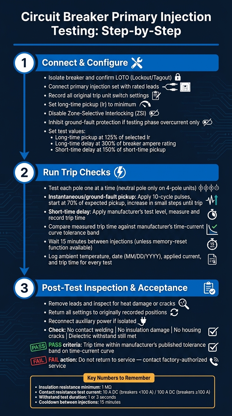
Circuit Breaker Short-Circuit Testing: Step-by-Step Process
Step 1: Connect the Breaker and Set the Target Test Current
Once the breaker is isolated and inspected, you can start the primary injection test. After isolation is confirmed, connect the primary injection set using rated leads. Stick with clean, undamaged connectors and rated cables.
Before you change anything, record every original trip unit switch setting. Then set the long-time pickup (Ir) to its minimum position and disable Zone-Selective Interlocking (ZSI) if the breaker has it. If the test is limited to phase overcurrent, inhibit ground-fault protection as well.
Next, set the long-time pickup, long-time delay, and short-time delay to the test values given by the manufacturer. Use these reference points:
- Long-time pickup verification: 125% of the selected long-time pickup
- Long-time delay check: 300% of the breaker ampere rating
- Short-time delay verification: 150% of the short-time pickup setting
Step 2: Run Instantaneous and Short-Time Trip Checks
With the current set, test each pole one at a time. Test the neutral pole only on four-pole units. For instantaneous and ground-fault pickup, use the pulsed current method: apply about 10-cycle pulses, begin at 70% of the expected pickup, and increase in small steps until the breaker trips. This gives you a clean way to find pickup points without overheating the unit.
For short-time delay, use the manufacturer's test level and compare the measured trip time with the published curve. Record the actual measured current and trip time for each test. Then compare those results against the manufacturer's time-current curve. To pass, the results need to land within the curve's tolerance band.
"Primary injection testing can be used to ensure that all trip system connections have been correctly made." - Schneider Electric
For each entry, log the ambient conditions and the date in MM/DD/YYYY format, such as 07/07/2026. Also, wait 15 minutes between injections unless the breaker has a memory-reset function.
Step 3: Review Lab Short-Circuit Test Sequences and Post-Test Condition
After the pickup and delay checks, inspect the breaker again and confirm that it still meets the test standard. Use the lab rating data as your benchmark, then check the breaker for any damage after field injection.
Withstand tests apply a specified fault current, usually for 1 or 3 seconds, followed by inspection for contact deformation, insulation damage, and mechanical integrity. A passing breaker should show no major erosion, no housing cracks, and it should hold the post-test dielectric withstand voltage without breakdown.
After any field injection test, remove the leads, inspect for heat or damage, and return all settings to the recorded positions. Reconnect auxiliary power if it was isolated.
Acceptance Criteria, Records, and Final Takeaways
How to Judge Pass or Fail Results
After the final trip check and inspection, use the test data to decide if the breaker can go back into service.
A breaker passes when its measured trip time stays within the manufacturer's published tolerance band on the time-current curve. For short-time withstand checks, the breaker must trip within the curve, show no contact welding or insulation damage, and return to service after cool-down. It should also still meet dielectric requirements after testing.
One point matters here: do not use contact resistance alone to reject a breaker.
If a result lands outside the tolerance band, stop before calling it a failure. First, verify the test current, connections, and source voltage. Also record the test supply voltage during the run. That detail can help explain a result that looks off at first glance.
What to Include in the Test Report
Your report should show the exact numbers used to make the pass-or-fail call. Include the following:
| Category | Required Information |
|---|---|
| Identification | Breaker type, series, catalog number, serial number |
| Ratings | Voltage class, ampere rating, interrupting rating (kA) |
| Test Parameters | Test current, test voltage |
| Results | Actual trip time (cycles or seconds), pickup levels, resistance values (micro-ohms) |
| Conditions | Ambient temperature (°F), date (MM/DD/YYYY), technician name |
| Setup | Test equipment, connection method, and applicable standard |
For U.S. projects, match the report format to IEEE C37.09 for high-voltage equipment or UL 489 for molded-case breakers. Also note the pre-test and post-test condition of the apparatus, including any visible damage and any settings changed during the procedure.
Conclusion: Core Points for Safe and Useful Short-Circuit Testing
A clean report closes out the test record and makes the next maintenance cycle much easier.
Short-circuit testing comes down to a few habits you can't skip:
- Verify ratings before making any connection
- Use properly rated equipment
- Follow a documented procedure
- Compare results against the manufacturer's time-current curves and the applicable standard
If a breaker fails, or if its ratings do not match the application, replace it with a correctly rated unit.
For replacement breakers, Electrical Trader offers new and used circuit breakers and related power distribution equipment. Before buying, confirm that the interrupting rating and voltage class match your system specs.
The test report is your paper trail. Keep it accurate, keep it complete, and file it where it can be found for the next inspection cycle.
FAQs
When should I use primary injection instead of secondary injection?
Use primary injection when you need a full check of the entire current path, including current sensors, internal wiring, contact integrity, and the trip unit.
This is the go-to method for making sure the breaker will trip the way it should during a fault or overload. It’s also required for newly installed ground-fault protection systems under NEC standards.
How do I know if a breaker’s Icu, Ics, and Icw ratings are enough for my system?
First, run a short-circuit study to find the maximum available fault current at the installation point.
For Icu and Ics, pick a breaker with a rating equal to or higher than that number.
Use Ics for critical loads that need service continuity after a fault. If the fault current is higher than Ics, an Icu-rated breaker may still operate, but it could need replacement after a single interruption.
For time-delayed coordination, also check that Icw can handle the fault current for the required duration.
What should I do if the breaker trips outside the manufacturer’s curve?
First, check your test conditions, equipment, and procedure to make sure the reading is correct for that breaker type.
If the breaker still trips outside the manufacturer’s tolerance band, that can point to a mechanical fault, bad sensors, or internal damage. At that point, the unit should be checked for replacement.