
How to Test Overcurrent Protection Devices
Testing overcurrent protection devices ensures they work when needed to prevent electrical damage or failure. These include molded case circuit breakers (MCCBs), fuses, and fusible switches, which protect circuits by interrupting excessive current flow. Regular testing is crucial for safety, compliance with the National Electrical Code (NEC), and maintaining reliable electrical systems.
Key Steps to Testing:
- Visual/Mechanical Checks: Inspect for cracks, discoloration, or loose connections. Operate handles to confirm smooth movement.
-
Electrical Function Tests:
- Insulation Resistance: Use a megohmmeter; readings below 1 MΩ may indicate issues.
- Contact Resistance: Measure voltage drop across contacts; high values suggest degradation.
- Trip Verification: Simulate overcurrent to confirm the breaker trips within manufacturer specifications.
- Safety Precautions: Always de-energize equipment, follow lockout/tagout (LOTO) procedures, and wear appropriate PPE as per NFPA 70E.
Tools You’ll Need:
- Digital Multimeter (DMM)
- Megohmmeter
- Primary Injection Test Set
- Torque Wrench
- Manufacturer Software for electronic trip units
Testing frequency varies by setting, but critical systems like hospitals should undergo annual checks. Proper documentation of test results helps track device performance and ensures compliance. Always reset devices to their original settings after testing and confirm safe operation before returning them to service.
Device Types and Testing Limits
Devices Covered in This Guide
This guide focuses on the most common overcurrent protection devices found in commercial and industrial systems: Molded Case Circuit Breakers (MCCBs), Miniature Circuit Breakers (MCBs), fuses, and fusible switches.
MCCBs are a key component in industrial setups. They come in three main types: thermal-magnetic, magnetic-only, and electronic-trip, each with specific testing requirements. On the other hand, MCBs are smaller, DIN rail-mounted devices with ratings up to 125A.
Fuses operate differently. They use a metal element that melts when an overcurrent occurs, meaning they must be replaced after activation. Testing for fuses primarily involves checking continuity, unlike circuit breakers, which require operational trip tests. Fusible switches combine a mechanical disconnect with fuse protection in one unit, offering a compact solution for overcurrent protection.
"A circuit breaker that looks right, feels solid, and carries the correct markings but hasn't been properly tested is not a circuit breaker - it is a packaging box." - TradeAider
By understanding these devices, we can better explore the specific testing procedures that ensure their reliable operation.
Levels of Testing
Testing these devices involves several evaluation levels, each tailored to the unique characteristics of the components listed above.
| Level | Parameters Assessed | Key Measurements |
|---|---|---|
| Visual/Mechanical | Physical condition and operation | Housing integrity, terminal tightness, handle movement |
| Functional | Trip mechanism performance | Mechanical latch release using the "Test" button |
| Insulation Resistance (IR) | Insulation quality | Leakage current with 500–1,000V DC; target >1 megohm |
| Contact/Pole Resistance | Connection quality | Voltage drop across contacts; target <100 micro-ohms |
| Primary Injection | Full operational performance | Response to high-current injection through the main power path |
The first step in any inspection is the visual and mechanical check. Studies show that these initial checks can identify about 30% of potential MCCB issues before moving on to more detailed electrical tests. Functional tests follow, ensuring the trip mechanism works as intended. More advanced evaluations, such as insulation resistance and contact resistance tests, provide a deeper understanding of electrical performance.
Primary injection testing is considered the most thorough method. It involves injecting high current through the breaker’s main power path to assess the entire protection chain. For electronic-trip MCCBs, secondary injection testing is a quicker alternative, using low-level signals to evaluate the trip unit. While this method is practical for routine maintenance, primary injection testing is recommended annually for critical circuits, such as those in hospitals or emergency systems. For standard commercial setups, a basic inspection every three years, combined with advanced testing every five to ten years, is usually adequate.
sbb-itb-501186b
Safety Precautions and Tools Needed
Safety Steps to Follow Before Testing
Before starting any testing, fully de-energize and lock out the equipment. This means following lockout/tagout (LOTO) procedures for all energy sources connected to the device. Don’t stop at electrical energy - address mechanical energy stored in springs and any pneumatic pressure as well.
Once LOTO is in place, confirm zero energy using the "Test-Check-Test" method. Here’s how it works: first, test your voltage-sensing device on a known live source to confirm it’s functioning properly. Next, check the equipment to ensure there’s no voltage. Finally, re-test your voltage-sensing tool on the live source again. This process ensures both the equipment is safe to work on and your tool is reliable.
"Always use a properly rated voltage sensing device to confirm power is off." - Schneider Electric Field Testing & Maintenance Guide
Choose your personal protective equipment (PPE) according to NFPA 70E guidelines. This involves considering factors like short-circuit current, fault clearing time, and work distance. If these values are unclear, calculate them before proceeding. At a minimum, wear arc-rated clothing, insulated rubber gloves (Class 00 or 0), and safety glasses or an arc-rated face shield.
Don’t forget additional safety steps: set up barricades around your work area to prevent accidental entry, and clearly tag or label the specific device being serviced. As Paul Chamberlain, Safety Manager at Asplundh Electrical Testing, LLC, emphasizes, "The person doing the work must recognize and understand the hazards that may be encountered while performing the tasks."
With safety covered, let’s move on to the tools you’ll need.
Tools Required for Testing
Having the right tools on hand can make testing safer and more efficient. Below is a table of essential equipment and their specifications.
| Tool | Primary Use | Key Specification |
|---|---|---|
| Digital Multimeter (DMM) | Voltage, continuity, resistance checks | CAT III or CAT IV rated (600V minimum) for panel work |
| Megohmmeter | Insulation resistance testing | 500–1,000 Vdc capacity; investigate any reading below 1 MΩ |
| Micro-ohmmeter / DLRO | Contact resistance measurement | 10A DC for breakers under 100A; 100A DC for 100A and above |
| Primary Injection Test Set | Trip-curve verification | High-current, low-voltage AC supply through the main power path |
| Secondary Injection Test Kit | Electronic trip unit testing | e.g., UTS3; simulates fault signals without high primary current |
| Torque Wrench | Terminal connection tightness | Match manufacturer specs - typically 20–35 in-lb for smaller units |
| Manufacturer Software / Interface | Trip unit configuration and reporting | e.g., EcoReach, EcoStruxure Power Commission via Mini USB |
Here are a few practical tips for using these tools effectively:
- Disconnect control circuits and Voltage Power Supply (VPS) modules before performing high-voltage insulation tests on modern electronic breakers. Skipping this step could damage the trip unit permanently.
- Clean the breaker thoroughly before insulation resistance testing. Surface contamination can lower readings below 1 MΩ, leading to false failure results.
- Perform an instantaneous primary injection test before checking contact resistance. The high-current pass removes oxidation from contacts, ensuring more accurate resistance measurements afterward.
How to Test Overcurrent Protection Devices
How to Test Overcurrent Protection Devices: Step-by-Step Guide
Visual and Mechanical Checks
Start with a careful visual inspection, ensuring all safety protocols and tools are in place. As one industry expert explains: "Inspection, exercising, and testing are three different activities, and confusing them is a common maintenance mistake". Skipping this step can lead to missed issues that are often visible to the naked eye.
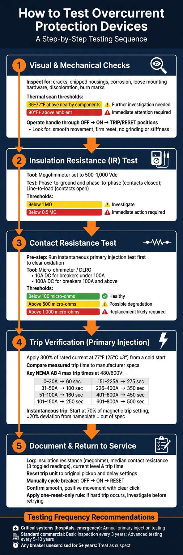
Inspect the device methodically. Check for cracks, chipped housings, corrosion on terminals, loose mounting hardware, and any signs of discoloration or burn marks that might indicate overheating or arc damage. Even slight scorching near a terminal could signal a loose connection that's been generating heat under load. During a thermal scan, temperature differences between 36–72°F above nearby components should prompt further investigation, while differences of 90°F or more above ambient temperature require immediate attention.
Once the visual inspection is complete, move on to mechanical checks. Operate the handle through its OFF, ON, and TRIP/RESET positions, noting any unusual resistance or feedback. The movement should feel smooth and consistent, with a firm reset. If the handle feels stiff, produces grinding sounds, or fails to hold the reset position, it could indicate internal corrosion or mechanical wear. As C&H Electric points out: "A breaker that trips electrically but sticks mechanically is just as dangerous as one that fails to detect a fault".
After confirming the device’s visual and mechanical integrity, proceed to electrical function tests for a full evaluation.
Electrical Function Tests
Electrical tests are essential for verifying the device's performance after completing the initial checks. These tests typically follow this sequence: insulation resistance (IR), contact resistance, and trip verification.
For IR testing, use a megohmmeter set between 500–1,000 Vdc. Test phase-to-ground and phase-to-phase with contacts closed, then test line-to-load with contacts open. Any reading below 1 MΩ should be investigated, and readings under 0.5 MΩ often require immediate action. Before measuring contact resistance, perform an instantaneous primary injection test to clear oxidation from the contacts, which improves accuracy. Healthy contacts should show resistance below 100 micro-ohms. Readings above 500 micro-ohms may indicate degradation, and values exceeding 1,000 micro-ohms typically call for replacement.
For trip characteristic testing, apply 300% of the rated current at 77°F (25°C ±3°) from a cold start. Compare the measured trip time to the manufacturer's specifications. The table below outlines the maximum allowable trip times according to NEMA AB 4:
| Rated Continuous Current | Max Trip Time (240V) | Max Trip Time (480/600V) |
|---|---|---|
| 0–30 A | 60 sec. | 60 sec. |
| 31–50 A | 80 sec. | 100 sec. |
| 51–100 A | 140 sec. | 160 sec. |
| 101–150 A | 200 sec. | 250 sec. |
| 151–225 A | 230 sec. | 275 sec. |
| 226–400 A | 300 sec. | 350 sec. |
| 401–600 A | N/A | 450 sec. |
| 601–800 A | N/A | 500 sec. |
For instantaneous (magnetic) trip testing, start at 70% of the magnetic trip setting and gradually increase the current until the breaker trips. If the trip current deviates by more than ±20% from the nameplate value, the device is out of spec. For devices with electronic trip units, use secondary injection testing to verify long-time, short-time, and instantaneous protection settings. Ensure these settings align with your facility’s coordination study.
Reviewing Results and Next Steps
How to Read and Record Test Results
Once you've wrapped up testing, getting the documentation right is just as important as the testing itself. Before you even started, you should have noted all the pickup and delay settings on any electronic trip unit. This ensures you can reset the device back to its original configuration when you're done.
For every test, make sure to log specific values like:
- Insulation resistance (in megohms)
- Median contact resistance (from three toggled readings)
- Current level and trip time (to compare against the manufacturer's trip curve)
The table below serves as a quick guide to determine whether results meet acceptable thresholds or require further investigation:
| Test Type | Threshold | Action |
|---|---|---|
| Insulation Resistance | < 1 megohm | Investigate |
| Contact Resistance | > Manufacturer's max micro-ohms/pole | Investigate |
| Trip Time | Outside trip curve tolerance band | Evaluate test conditions first |
| 1,200A+ Adjustable Breakers | No arc-energy reduction documentation | Non-compliant per NEC 240.87 |
If results fall outside the acceptable range, don't rush to reject the device. According to NEMA AB 4: "The millivolt drop of a circuit breaker pole can vary significantly due to inherent variability in the extreme low resistance of the electrical contacts and connectors. Such variations do not necessarily predict unacceptable performance and shall not be used as the sole criteria for determination of acceptability". Instead, double-check the ambient conditions and equipment setup to rule out external factors. For accurate readings, ensure your test cables are at least 4 feet long per connection and sized according to NEC Table 310.16.
As more facilities adopt condition-based maintenance, keeping detailed records becomes even more crucial. Comparing current test results with historical data can reveal whether a borderline reading is stable or worsening over time. This approach provides more context than relying on a single test result.
Once everything is recorded, you’re ready to safely return the device to service.
Returning a Device to Service
After documenting everything, confirm that all test results meet the required thresholds. Reset the trip unit to the exact pickup and delay settings you recorded before testing. Next, manually cycle the breaker through its OFF, ON, and RESET positions. Pay attention to how it feels - smooth, positive movement with a clear click is what you want. If it’s stiff, grinding, or doesn’t hold the ON position, the device isn’t ready for service.
When removing test leads and clamps, check the terminals for any signs of scoring or damage. If you notice an ozone smell or see discoloration near the lugs, stop and investigate immediately.
In industrial settings, follow a one-reset-only rule: if a breaker trips immediately upon reset (a "hard trip"), stop and investigate for a permanent fault or insulation issue before trying again. As Weisho Electric explains: "If a breaker is in a 'Center/Tripped' position, it has detected a fault; if it is 'OFF', it was operated manually." This distinction is key to understanding whether the trip was incidental or points to an unresolved fault.
Conclusion
Testing overcurrent protection devices is critical for distinguishing dependable systems from those that could fail under stress. As Bowtie Engineering aptly states:
"Circuit breakers are your electrical system's last line of defense. When a fault occurs, the breaker is what stands between a manageable incident and a catastrophic arc flash event."
This sentiment aligns with the detailed testing and inspection practices discussed throughout this article.
The key points to remember? Prioritize safety, conduct thorough testing, and maintain detailed documentation. Always follow safety protocols: de-energize equipment, confirm a zero-energy state, and use both visual and functional tests to identify potential issues. Combining these tests - like insulation, contact, and injection testing - provides a complete evaluation, uncovering problems such as calibration drift or dried-out lubrication. These steps not only ensure immediate safety but also help shape effective long-term maintenance plans.
For industrial settings, test critical circuit breakers every one to three years. Any breaker left unexercised for more than five years should be treated as suspect. The 2023 edition of NFPA 70B underscores the importance of regular breaker inspection and testing.
If you're looking for overcurrent protection devices, replacement breakers, or testing equipment, check out Electrical Trader. They offer a wide range of new and used electrical components from trusted brands like Siemens, ABB, GE, Square D, and Eaton.
FAQs
What’s the difference between primary and secondary injection testing?
Primary injection testing involves sending current through the entire protection system, including the breaker’s primary path, CT wiring, and trip unit. This method ensures a complete check of the system's functionality. However, it requires more time, specialized expertise, and larger equipment to perform.
On the other hand, secondary injection testing focuses solely on the trip unit's logic. By simulating fault currents on the CT’s secondary side, this approach is faster, easier to carry out, and relies on portable equipment, making it a more cost-effective option.
When should a breaker or fuse be replaced instead of retested?
A fuse is a one-time-use device, so it needs to be replaced every time it blows. Circuit breakers, on the other hand, should be replaced if you notice any of the following issues: the test button doesn’t work, the housing shows signs of damage, discoloration, or a burnt smell, the handle feels loose, it trips often without a clear reason, it’s been in use for over 15–20 years, or it has gone through a major short-circuit accompanied by sparks or loud noises.
How do I choose the right PPE level for breaker testing?
To choose the right personal protective equipment (PPE) for breaker testing, start by assessing the potential incident energy exposure using arc flash calculations. Be sure to follow safety standards like NFPA 70E, OSHA, or CSA regulations, and confirm that all PPE is Arc Rated (AR).
When working on live panels, use test instruments rated for CAT III or CAT IV, depending on the equipment and environment. Additionally, wear voltage-rated gloves, eye protection, and arc-rated clothing appropriate to the hazard level determined by your calculations. Safety should always come first!


