
Ultimate Guide to MCCB Maintenance
Molded Case Circuit Breakers (MCCBs) are critical for electrical safety in industrial and commercial systems. Regular maintenance ensures they function properly, preventing costly failures and hazards. Here's a quick breakdown:
- Why It Matters: MCCBs protect against overloads and short circuits. Poor maintenance can lead to failures, downtime, and safety risks.
-
Key Maintenance Areas:
- Visual Inspections: Look for cracks, discoloration, or overheating signs.
- Mechanical Testing: Toggle switches and trip functions to ensure smooth operation.
- Electrical Testing: Check insulation resistance, contact resistance, and trip mechanisms.
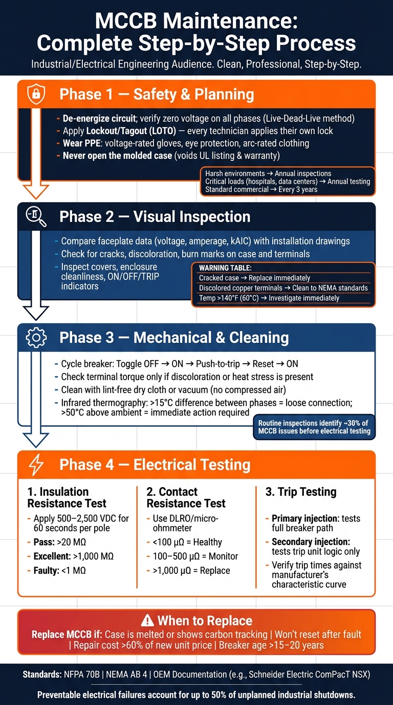
- Safety First: Always de-energize circuits, follow lockout/tagout (LOTO) procedures, and wear proper PPE.
- Standards to Follow: Refer to NFPA 70B and NEMA AB 4, but always prioritize OEM guidelines.
Neglecting MCCB maintenance can lead to 50% of preventable electrical failures in industrial setups. Regular checks, proper cleaning, and timely replacements are essential for reliability and safety.
MCCB Maintenance Checklist: Step-by-Step Guide
Safety and Planning for MCCB Maintenance
Safety Protocols and Best Practices
When servicing an MCCB, the first step is to de-energize the equipment. This involves opening the upstream disconnect or feeder breaker and verifying zero voltage on all phases using a properly rated meter. Always follow the "Live-Dead-Live" method to ensure safety.
Lockout/Tagout (LOTO) is a critical safety measure and a legal requirement under OSHA standards. Every technician working on the equipment must apply their own lock and tag to the disconnecting device to prevent accidental re-energization.
Personal protective equipment (PPE) is non-negotiable. Technicians should wear voltage-rated gloves, eye protection, and arc-rated clothing whenever working near energized components.
Another key rule: never open the molded case of an MCCB. Doing so voids the UL listing, warranty, and calibration.
"The molded case of an MCCB must never be opened because it protects factory-calibrated parts that cannot be restored in the field without specialized equipment and training." - Conor, Author, Oohmage
By ensuring de-energized conditions, technicians can safely evaluate how environmental and load factors affect the breaker.
Factors That Affect Maintenance Schedules
Once safety protocols are in place, understanding the operating environment and load conditions is essential for determining maintenance schedules.
Environmental factors can greatly influence how often an MCCB requires attention. For instance:
- High humidity speeds up insulation wear.
- Conductive dust and chemical vapors lead to oxidation and can jam mechanical parts.
- Continuous vibration gradually loosens connections.
Load conditions are equally important. A breaker operating near its thermal limit daily endures heat stress, which can warp its casing and damage wire insulation. Similarly, breakers left in the "ON" position for extended periods risk mechanical issues due to dried lubricants and accumulated dust.
The criticality of the circuit also plays a role. Systems like hospital emergency circuits or data center power feeds - where failures could have severe consequences - require annual, comprehensive testing. On the other hand, standard commercial circuits typically only need testing every three years.
| Factor | Impact on Maintenance Frequency |
|---|---|
| Harsh environment (dust, humidity, vibration) | Annual inspections and frequent cleaning/exercising |
| Clean, climate-controlled environment | Extended intervals - 2 to 3 years for exercising |
| Critical loads (life safety, data centers) | Annual comprehensive testing, including injection testing |
| Standard commercial loads | Basic testing every 3 years |
"Electrical testing tells you whether a breaker should work. Exercising tells you whether it can still move when asked to." - Oohmage
Using OEM Documentation for Maintenance Planning
In addition to environmental and load considerations, OEM documentation provides essential details for planning effective maintenance.
OEM guidelines are the definitive source for MCCB maintenance specifics, including torque values, lubrication points, and conditions that may require accelerated servicing. While industry standards like NFPA 70B offer general guidance, OEM documentation tailors recommendations to the unique design of each breaker model.
For example, Schneider Electric's ComPacT NSX User Guide outlines optimal operating conditions, such as:
- An average annual temperature below 77°F (25°C) outside the switchboard
- Relative humidity under 70%
- Loading kept below 80% of rated current continuously
Exceeding these thresholds shortens the breaker's lifespan and increases the likelihood of malfunctions.
"The maintenance programs apply to optimum environmental and operating conditions. Outside these limits circuit breakers are subject to accelerated aging which can quickly lead to malfunctions." - Schneider Electric
Some OEMs also specify component replacements that go beyond routine maintenance. Schneider Electric, for instance, requires certain parts, like MN/MX trip releases, to be replaced every 5 years, regardless of their condition. Such details emphasize the importance of referring directly to the manufacturer's documentation for accurate maintenance planning.
sbb-itb-501186b
How to Test Breakers ep1: Thermal Magnetic Trip Units
Routine Inspection and Preventive Maintenance
Once safety measures are in place and scheduling is sorted, routine inspections become the next step. These involve basic visual and mechanical checks, which can identify roughly 30% of MCCB (Molded Case Circuit Breaker) issues before moving on to electrical testing. This step plays a key role in avoiding unexpected breakdowns and keeping operations safe. Routine inspections pave the way for more detailed mechanical and electrical evaluations.
Visual Inspection Checklist
Start by comparing the breaker's faceplate data - voltage, amperage, and interrupting capacity - with the installation drawings and coordination studies. Any discrepancies here could signal a problem that needs addressing before it escalates.
Next, examine the breaker's physical condition:
- Look for cracks or physical damage on the molded case. A cracked case compromises short-circuit protection and calls for immediate replacement.
- Check for discoloration or burn marks on the case, terminals, or insulation - these are warning signs of overheating.
- Ensure all covers are intact, the enclosure is clean and dry, and that the ON/OFF/TRIP indicators are visible and functioning properly.
- For units with Visi-Trip LEDs, pay attention to the flash patterns. A quick two-second flash indicates low battery (20% remaining), while a slower flash lasting six hours signals the breaker requires inspection.
"Visual inspections during operation can be performed any time electrical workers or maintenance personnel are in the vicinity of the electrical equipment." - Schneider Electric
Here’s a quick guide to common inspection findings and how to address them:
| Inspection Finding | Potential Issue | Required Action |
|---|---|---|
| Cracked molded case | Reduced short-circuit integrity | Immediate replacement |
| Discolored copper terminals | Overheating | Clean and dress to NEMA standards |
| Discolored aluminum connectors | Severe overheating | Replace connector and damaged conductor |
| Temperature > 140°F (60°C) | Overload or poor connection | Investigate cause immediately |
| Pitted I-Line jaws | Connection failure | Replace circuit breaker (jaws are not field-replaceable) |
Mechanical Cycling and Torque Checks
Once the visual inspection is complete, test the breaker's mechanical operations to confirm reliable performance.
Cycle the breaker by toggling the handle OFF, then ON, and use the push-to-trip button to trigger a trip. Reset it and return it to the ON position. This ensures the mechanical linkages move freely and the trip function is responsive. Schneider Electric advises performing this test at least once a year, as inactivity can lead to dust, moisture, or dried lubricants seizing the mechanism - right when you need it most.
When performing maintenance, check terminal connection tightness using a calibrated torque wrench. However, if there’s no discoloration or heat stress, it’s often better to leave the connections undisturbed. Re-torquing unnecessarily can weaken a stable joint.
Cleaning and Infrared Thermography
Proper cleaning is key to maintaining the breaker’s functionality. Use a lint-free dry cloth or vacuum to remove dust and debris. Avoid compressed air, as it can push contaminants deeper into the mechanism instead of clearing them. For terminal pads and bus bars, stick to non-abrasive cleaners to prevent stripping the plating, which could speed up joint deterioration.
Infrared thermography is a powerful tool for spotting developing issues while the breaker is still in operation. Allow the energized breaker to stabilize for about three hours before scanning. A temperature difference of more than 15°C between phases often points to loose connections or deteriorating contacts. A reading that exceeds 50°C above ambient temperature is a serious warning sign that demands immediate action.
Electrical Testing for MCCBs
Electrical testing ensures that a breaker will function correctly under fault conditions, helping to identify issues like degraded insulation or worn contacts before they lead to failure.
Insulation Resistance Testing
Insulation resistance testing uses a megohmmeter to apply high DC voltage across the breaker's insulation and measure leakage current. Before starting, always de-energize the circuit and disconnect surge protection devices or power electronics. Safety gear, including high-voltage gloves and safety glasses, is essential during this process.
To perform the test:
- Connect the high-voltage lead to one pole while grounding the remaining poles, including the frame, line, and load sides.
- Repeat this process for each pole.
- Apply the test voltage (commonly 500 VDC, 1,000 VDC, or 2,500 VDC based on the breaker's rating) for 60 seconds.
- Watch for rapid reading fluctuations, which may indicate insulation breakdown.
How to interpret the results:
| Insulation Condition | Resistance Reading |
|---|---|
| Excellent / New | >1,000 MΩ (1 GΩ) |
| Acceptable | 20 MΩ to 1,000 MΩ |
| Minimum (IEC, >120V systems) | >1 MΩ |
| Faulty / Deteriorating | Below 1 MΩ or manufacturer threshold |
"A passing test should be at a minimum of 20 MΩ. We recommend values higher than 1000 MΩ." - Julia Klein, Product Manager, BARTEC
Factors like heat, humidity, and dust can degrade insulation over time. For most cases, annual testing is sufficient, but harsher environments may require testing every three to six months.
After verifying insulation, the next step is to assess contact integrity using resistance testing.
Contact Resistance and Millivolt Drop Testing
This test, also known as a millivolt drop or pole resistance test, measures the resistance of the breaker's closed conductive path, including contacts, terminals, and internal connections. It helps detect oxidation, contamination, or erosion that might not be visible during a visual inspection.
For accurate results, use a DLRO or micro-ohmmeter instead of a standard multimeter. Recommended test currents are:
- 10 A for breakers rated below 100 A
- 100 A for breakers rated above 100 A
Limit the test current to one minute to prevent overheating the contacts and skewing the results.
Resistance values and actions:
| Resistance Value | Condition | Recommended Action |
|---|---|---|
| < 100 micro-ohms | Healthy | Routine maintenance |
| 100–500 micro-ohms | Marginal | Monitor and trend |
| 500–1,000 micro-ohms | Warning | Investigate for oxidation or wear |
| > 1,000 micro-ohms | Critical | Immediate repair or replacement |
If resistance is unexpectedly high, try cycling the breaker two or three times and retest - it may clear minor surface contamination. A 50% difference in resistance between poles is a red flag that requires further investigation.
"A good rule of thumb to follow is to investigate any breaker whenever a 50% deviation of resistance values appears between any pole." - John Shanks, Product Manager, AVO International
Trip Testing and Functional Verification
Once insulation and contact resistance are verified, the next step is to test the trip functions to ensure the breaker's protective mechanisms work as intended. Trip testing checks both thermal and magnetic triggers to confirm they operate within the manufacturer's specified parameters. There are two main methods: primary injection and secondary injection.
- Primary injection: Sends a high current through the entire breaker path, including contacts and the trip unit, simulating real fault conditions. This method tests both the mechanical trip mechanism and the trip unit's response.
- Secondary injection: Injects a signal directly into the trip unit, bypassing the contacts. It checks the trip unit logic but does not assess contact integrity.
For thermal trigger testing, apply a preset overload current and confirm the breaker trips within the time frame specified by its characteristic curve. For magnetic trigger testing, use current pulses to simulate high-fault conditions. For example, a Type C breaker typically trips at 5 to 10 times its nominal rating (_I_n). Always consult the manufacturer's characteristic curve to determine the acceptable pass/fail thresholds.
Keep in mind that repeated high-current pulses during magnetic testing can wear down some MCCB designs. Ensure the breaker is rated for multiple fault simulations before proceeding.
Troubleshooting and Replacing MCCBs
Common MCCB Problems and How to Diagnose Them
MCCB (Molded Case Circuit Breaker) problems often come with clear warning signs. By combining visual inspections with mechanical checks, you can catch many issues early, even before diving into electrical testing. These methods work hand-in-hand with routine maintenance to ensure timely repairs or replacements.
| Symptom | Likely Root Cause | Recommended Action |
|---|---|---|
| Overheating / burning smell | High contact resistance or loose lugs | Use thermal imaging and perform contact resistance testing |
| Nuisance tripping | Overload, harmonics, or incorrect settings | Measure load current and verify settings |
| Won't reset / won't close | Internal mechanical failure or shock damage | Check mechanical operation; replace if binding occurs |
| Handle feels "spongy" | Damaged internal linkages or springs | Cycle mechanically and inspect for internal binding |
| Carbon tracking (soot) | Escaping arc gases / dielectric failure | Perform a visual inspection; replace immediately |
One commonly misunderstood issue is nuisance tripping. Before assuming the breaker is defective, consider whether harmonics from variable frequency drives (VFDs) or high motor inrush currents might be the real culprits. A load study can help confirm whether the breaker is responding correctly to broader system conditions rather than malfunctioning.
Thermal imaging is another powerful diagnostic tool. A temperature rise of about 18°F (10°C) above ambient is generally acceptable. However, if the rise exceeds 122°F (50°C), immediate action is required.
Spotting these warning signs early can help you decide whether repair or replacement is the safest path forward.
When to Replace an MCCB
Certain conditions make replacing an MCCB non-negotiable. If the case is melted, shows carbon tracking, emits a persistent burning odor after a fault, or won’t reset following a fault, the breaker has sustained internal damage that field repairs cannot fix.
It’s crucial to understand the limitations of MCCB repair. The molded case is factory-sealed to safely contain arc energy during operation. This design means internal components like contacts, arc chutes, and springs cannot be serviced in the field. Opening the case not only voids the UL safety certification but also shifts liability to the technician. However, external accessories - such as shunt trips, auxiliary contacts, terminal lugs, and modular electronic trip units - can be replaced if needed.
As a general rule, if repair costs exceed 60% of the cost of a new breaker, or if the breaker is more than 15–20 years old, replacement is the better option.
Once a replacement is necessary, the next step is sourcing the right unit.
How to Source a Replacement MCCB
Before ordering a replacement MCCB, double-check the specifications of the unit being replaced. The new breaker must match the original’s continuous current rating, short-circuit interrupting capacity (kAIC), voltage rating, and trip characteristic (thermal-magnetic or electronic). A mismatch in any of these areas could lead to inadequate protection or code violations.
For commonly used models, sourcing a replacement is usually straightforward. However, finding older or discontinued breakers can be more challenging. Platforms like Electrical Trader allow buyers to search for both new and used MCCBs from various brands, which is especially helpful when standard suppliers don’t have the required model in stock.
Once the replacement breaker is installed, it’s essential to perform insulation and contact resistance tests. Be sure to document the model, serial number, and test results. This record will serve as the foundation for future maintenance cycles.
Conclusion and Key Takeaways
Keeping MCCBs in good working order is simple when regular maintenance becomes a habit. Did you know that preventable electrical failures are responsible for up to 50% of unplanned industrial shutdowns? A consistent inspection routine can stop most of these disruptions before they happen, making the checks outlined earlier an essential part of your maintenance strategy.
Focus on three key areas: visual inspections, mechanical cycling, and electrical testing. Visual inspections help spot physical damage, mechanical cycling prevents parts from seizing, and electrical testing tracks performance trends. Establishing baseline readings during commissioning is essential - one data point alone doesn’t tell the full story. However, comparing results over time helps identify gradual wear and tear long before it leads to failure.
"Test results only become meaningful when you compare them against limits, baselines, and operating context. A number by itself is not a diagnosis." - Conor, Author
It’s also important to remember that MCCBs are factory-sealed for a reason. If internal components are compromised, the breaker must be replaced entirely - field repairs simply can’t restore the necessary protection against arc energy.
Stick to a regular inspection schedule, keep thorough records, and adjust the frequency of checks based on environmental conditions. For example, breakers in harsh, dusty, or coastal environments need inspections every six months instead of annually. This disciplined approach not only boosts system reliability but also enhances safety. In the end, it’s this level of care that separates well-maintained systems from those prone to sudden failures.
FAQs
How do I decide how often to maintain an MCCB?
To figure out how often you should maintain your MCCB (Molded Case Circuit Breaker), start by checking the manufacturer’s recommendations for your specific model. Then, think about factors like the environment it operates in - dust, humidity, or vibration can all impact performance - and how critical the equipment is to your system.
Here’s a general idea of maintenance intervals:
- Every 6 months: Clean and tighten the terminals to ensure proper connections.
- Annually: Do a visual inspection, use thermal imaging to check for overheating, and perform manual testing.
- Every 3–5 years: Test the trip mechanism to make sure it’s functioning correctly.
Always document your findings. This helps you identify patterns over time and fine-tune your maintenance schedule if needed.
What test results indicate an MCCB should be replaced?
If an MCCB (Molded Case Circuit Breaker) exhibits physical damage - such as cracks, warping, or melted plastic - it’s a clear sign of thermal or structural stress and should be replaced. Carbon tracking, which appears as soot or burn marks, points to a loss of dielectric strength and is another red flag. Mechanical problems, like a toggle that feels stiff or fails to lock, often indicate internal failure. Additionally, if electrical testing uncovers deviations from the manufacturer’s specifications, it’s time for a professional evaluation or replacement.
What should I record after MCCB testing for future baselines?
To establish a solid foundation for maintenance, make sure to document both test conditions and results thoroughly. For contact resistance tests, record the millivolt drop and the test current for each pole, ensuring you take three readings per pole. When performing overcurrent trip tests, log the time it takes from applying the current to the breaker tripping. Keep all these records alongside inspection findings to track performance trends effectively over time.


