
Checklist for MCCB Selection
Choosing the right MCCB (Molded Case Circuit Breaker) is critical for safety and system reliability. Here's a quick guide to ensure you don't miss any important factors:
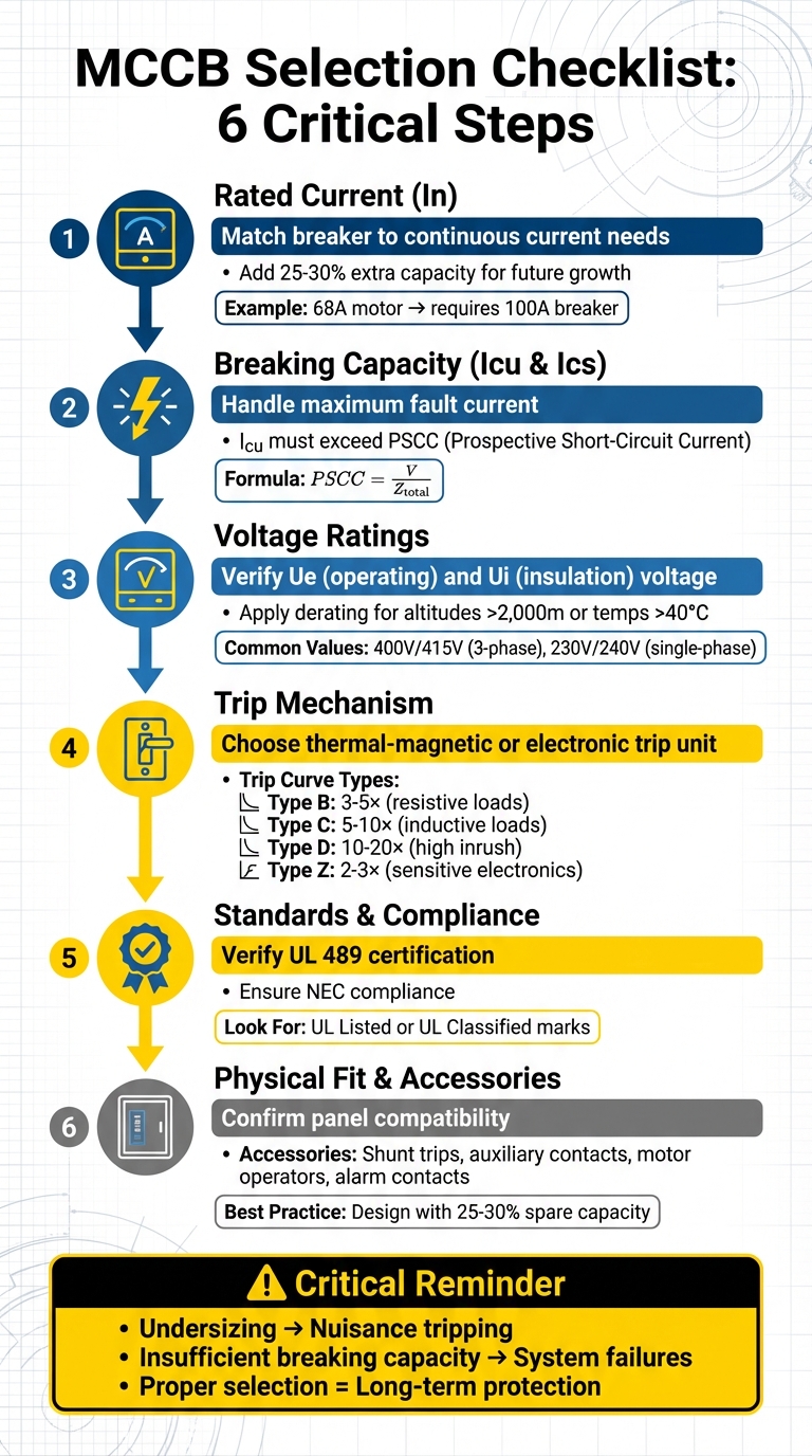
- Rated Current (In): Match the breaker to your system's continuous current needs. Add 25–30% extra capacity for future growth.
- Breaking Capacity (Icu & Ics): Ensure the MCCB can handle the maximum fault current in your system. Icu should exceed the calculated fault current (PSCC).
- Voltage Ratings: Verify operating voltage (Ue) and insulation voltage (Ui) compatibility. Consider derating for high altitudes or temperatures.
- Trip Mechanism: Choose between thermal-magnetic or electronic trip units based on load type and precision needs. Adjust settings for overload, short-circuit, and ground fault protection.
- Standards & Compliance: Look for UL 489 certification and ensure NEC compliance for a safe and legal installation.
- Physical Fit: Confirm the MCCB fits your panel and supports necessary accessories like shunt trips, auxiliary contacts, or motor operators.
Key takeaway: A structured selection process minimizes risks like nuisance tripping or system failures and ensures long-term protection for your electrical setup.
For a deeper dive into MCCB selection, including technical calculations, testing, and installation tips, read on.
MCCB Selection Process: 6-Step Technical Checklist for Electrical Safety
Understanding MCCB: Function, Structure, Selection and tripping for Molded Case Circuit Breakers
Electrical Specifications to Verify
Getting the electrical specifications right is key to choosing the correct MCCB (Molded Case Circuit Breaker). These parameters ensure your breaker will protect your system effectively and perform reliably during faults.
Rated Current and Frame Size
The rated current (In) is the maximum continuous current the MCCB can handle without tripping. Meanwhile, the frame size (Inm or AF) refers to the physical housing and its maximum current-carrying capability. The frame determines the breaker's physical size and upper capacity, while the rated current is the adjustable protection setting for your specific circuit.
A single frame size can support multiple rated currents. For example:
- A DX100 frame accommodates currents ranging from 16A to 100A.
- A larger DX225 frame supports currents from 100A to 225A.
Both frames might offer a 100A option, but the DX225 provides a larger size and higher capacity for future needs.
For systems operating continuously (over three hours), select an MCCB rated at least 125% of the design current (Ib). For instance, a 50 HP, 415V three-phase motor with a full-load current of approximately 68A would require a 100A breaker. Adding 25–30% extra capacity is also a good practice to account for potential future load increases.
Rated Voltage and Insulation Voltage
The operating voltage (Ue) must match or exceed your system's nominal voltage. For three-phase systems, this is typically 400V or 415V, while single-phase systems usually operate at 230V or 240V. The rated insulation voltage (Ui) is the maximum voltage the MCCB's insulation can withstand during testing. This value is always higher than Ue, providing a safety margin against overvoltages.
Additionally, consider the rated impulse withstand voltage (Uimp), which indicates the MCCB’s ability to handle transient voltage spikes from lightning or switching surges. Common Uimp levels are 6kV, 8kV, or 12kV. If your system is installed at altitudes above 2,000 meters, apply derating factors to adjust both current and voltage ratings. Also, specify whether accessory control power is AC or DC when using features like shunt releases or motor drives.
Once voltage parameters are established, the next step is ensuring the MCCB’s fault interruption capacity aligns with system requirements.
Breaking Capacity Requirements
The breaking capacity defines the maximum fault current an MCCB can safely interrupt, making it a critical factor for protecting both personnel and equipment during short-circuit events.
There are two primary ratings to evaluate:
- Icu (Ultimate Short-Circuit Breaking Capacity): This is the highest fault current the MCCB can interrupt. After handling a fault at this level, the breaker may need replacement.
- Ics (Service Short-Circuit Breaking Capacity): This is the maximum fault current the MCCB can interrupt while remaining operational. It’s often expressed as a percentage of Icu (e.g., 25%, 50%, 75%, or 100%). For systems requiring high reliability, choose an MCCB where Ics equals 100% of Icu.
To ensure proper selection, calculate the Prospective Short-Circuit Current (PSCC) using the formula:
PSCC = V / Z_total, where:
- V is the system voltage.
- Z_total is the total impedance from the source to the MCCB.
The MCCB's Icu should meet or exceed the PSCC. Don’t forget to account for additional fault current contributions from motor loads, as well as the effects of cable length and transformer proximity on fault current levels.
| Breaking Capacity Type | Definition | Post-Fault Status | Critical Requirement |
|---|---|---|---|
| Icu (Ultimate) | Maximum fault current the MCCB can safely interrupt | May require replacement after a fault | Must be ≥ PSCC |
| Ics (Service) | Maximum fault current the MCCB can interrupt and remain operational | Can resume normal service immediately | Should be ≥ PSCC for critical systems |
Trip Mechanisms and Settings
Once you've confirmed the electrical specifications and breaking capacity, the next step is selecting a trip mechanism and adjusting its settings to match your system's load. This step ensures the trip mechanism is tailored to handle the demands of your setup.
Selecting the Trip Unit Type
There are two main types of trip units to consider:
- Thermal-magnetic trip units: These use a bimetallic strip for overload protection and an electromagnet for short-circuit protection. While effective, they are sensitive to changes in ambient temperature and offer limited customization options.
- Electronic trip units: These rely on current transformers and microprocessors, providing more precise protection. They maintain stability across temperature variations and include advanced features like real-time metering, SCADA integration, and diagnostics.
When choosing a trip curve, match it to your load type:
- Type B (3–5× rated current): Best for resistive loads.
- Type C (5–10× rated current): Suitable for general inductive loads.
- Type D (10–20× rated current): Ideal for loads with high inrush currents.
- Type Z (2–3× rated current): Designed for sensitive electronics .
Once you've selected the appropriate trip unit and curve, you can move on to fine-tuning its protection settings.
Adjusting Overload and Short-Circuit Protection
For systems with electronic trip units, settings can be adjusted to provide precise overload and short-circuit protection. These settings include:
- Long-time delay (L): Handles overload protection by setting the pickup current (Ir), which is adjustable between 0.4 and 1.0 times the rated current. The delay (tr) typically ranges from 2.2 to 27 seconds, allowing for temporary high currents, such as during motor startups.
- Short-time pickup (S): Configured to handle short circuits, usually adjustable between 1.5 and 10 times the pickup current. The delay ranges from 0.05 to 0.5 seconds, ensuring selective coordination by allowing downstream breakers to trip first during faults.
- Instantaneous setting (I): Provides immediate fault protection and can be set to trip at 2 to 40 times the continuous current rating.
- Ground fault protection (G): If needed, this setting is typically adjustable between 20% and 70% of the breaker's rated current.
To ensure everything functions as intended, test the MCCB under simulated fault conditions. Manufacturer selectivity tables can help confirm proper coordination between upstream and downstream devices. Typically, feeder breakers should be 125% to 300% larger than the branch units they supply.
sbb-itb-501186b
Compliance and Certification Checks
Once you’ve set up the trip settings, the next step is to ensure the MCCB meets all necessary safety standards and certifications. In the United States, the UL 489 standard is the go-to for molded-case circuit breakers, molded-case switches, and circuit-breaker enclosures. Additionally, installations must comply with the National Electrical Code (NEC) to guarantee they meet required safety codes. Completing these checks ensures a safer and compliant setup.
Required Certifications and Standards
Start by looking for the UL Mark on the MCCB. This indicates whether the product is UL Listed (tested for general safety across all hazards) or UL Classified (evaluated for specific features). For specialized needs, confirm the MCCB aligns with specific standards like UL 489A, UL 489B, or UL 489I.
Pay attention to application-specific markings. If the MCCB is being installed in a panelboard, check for "Class CTL" markings if circuit-limiting requirements apply. For lighting applications, look for "SWD" (suitable for switching fluorescent lighting) or "HID" (designed for high-intensity discharge lighting). Ensure the voltage and frequency ratings, such as 120/240V ac at 60 Hz, match your system. If the interrupting rating isn’t specified, the default is 5,000 A. Lastly, inspect terminal markings to confirm compatibility with the wire type (e.g., "Copper Only" or "Al/Cu") and check the specified tightening torque for secure connections.
Post-Selection Testing
Before installation, run a series of tests to confirm the MCCB is in proper working condition. Start with a visual inspection to identify any physical damage, wear, or loose connections. Use the manual trip button to simulate a fault; the breaker should promptly interrupt the current and reset without issues.
Conduct insulation resistance testing to check the molded casing's integrity by applying high voltage between live parts and ground. According to NETA standards, most low-voltage applications require a minimum insulation resistance of 100 Megohms, though 1 Megohm is the absolute minimum. Perform contact resistance testing to measure voltage drops across terminals, which can reveal abnormal resistance or contamination. NETA standards allow a tolerance of 50% between phases or up to 1.5 times the lowest measured value. Additional tests, such as AC dielectric withstand (Hipot) for detecting insulation failures and earth fault loop impedance testing for verifying ground fault protection, are also important. Always de-energize the circuit before testing and use calibrated tools to ensure connections are tightened to the correct torque values.
Physical and Installation Considerations
Once the electrical performance is confirmed, the next step is ensuring proper physical installation to keep the system running smoothly. After verifying compliance, check that the MCCB fits your panel and supports all required accessories. Make sure the breaker's dimensions align with the available panel space and clearance requirements. For higher current ratings or greater fault capacities, larger frames are typically needed. Measure the available space and compare it with manufacturer drawings. It's common practice to design layouts with 25% to 30% spare capacity in the enclosure. This not only allows room for future expansion but also ensures adequate airflow for cooling.
Size and Mounting Compatibility
The mounting style you choose can significantly affect ease of installation and future maintenance. Here are the main options:
- Fixed mounting: This method bolts the MCCB directly to the panel. It’s cost-effective but requires a full disconnection to replace the breaker.
- Plug-in mounting: This setup allows the breaker to plug into a fixed base. It enables quicker replacements without disturbing the main wiring.
- Draw-out (withdrawable) mounting: Ideal for critical circuits, this design lets you isolate and remove the MCCB with minimal disruption, making it a good choice for systems where uptime is crucial.
For smaller MCCBs, mounting on a standard 35mm DIN rail is often suitable.
Another critical factor is arcing distance. When a fault is interrupted, ionized gases are expelled, which means you need enough clearance between the MCCB and any bare conductors or grounded metal to avoid short circuits. If your distribution box has height limitations, consider "zero arcing" products to maintain safety. Additionally, the enclosure must accommodate the minimum bending radius for your conductor sizes and ensure proper ventilation to dissipate heat.
Connection options include mechanical lugs, compression lugs, extended spreaders, and busbar connectors. Front connections are easier to inspect, while rear connections save space but can limit accessibility.
Accessory Options
Accessories can enhance the functionality of your MCCB, so choosing the right ones is essential. Here are some common options:
- Shunt trips: These allow remote electrical tripping using a push button or sensor.
- Undervoltage releases: Automatically trip the breaker if voltage drops below a preset range, typically 35% to 70% of the rated voltage.
- Auxiliary contacts: Provide a remote indication of whether the breaker is open or closed.
- Alarm contacts: Specifically signal when the breaker trips due to a fault.
For auxiliary contacts, the standard heating current is usually 3A for frame ratings up to 225A and 6A for frames rated at 400A or more.
Other options include motor operators, which enable remote opening and closing. Use motor-driven operators for larger frames (≥400A) and electromagnetic types for smaller ones (≤225A). Rotary handles allow manual operation from outside the panel door, while mechanical interlocks are essential for setups where two adjacent MCCBs should not be closed simultaneously, such as in changeover schemes between two power sources.
Finally, make sure the control power supply (AC/DC) matches the accessory ratings. If advanced features like communication modules are available, consider whether they’re necessary for your application to avoid adding unnecessary costs or complexity.
Conclusion
A well-thought-out checklist brings together all the critical specifications and safety measures needed for selecting the right MCCB. This systematic approach plays a key role in ensuring both the safety and reliability of your electrical system. By carefully following each step - like calculating the design current, verifying the breaking capacity, and aligning trip curves with your load characteristics - you can address every important factor. Choosing the correct MCCB not only strengthens system performance but also enhances safety throughout the lifecycle of your electrical installation.
Taking a structured approach helps avoid costly errors. For instance, undersizing can cause nuisance tripping, while selecting a breaker with insufficient breaking capacity could lead to serious system failures. It’s also important to consider external conditions - ambient temperatures exceeding 104°F (40°C) or installations above 6,560 feet (2,000 meters) may require derating adjustments to maintain proper protection.
Once all criteria are checked, the next step is sourcing high-quality equipment. Platforms like Electrical Trader streamline this process, offering a centralized marketplace for both new and used MCCBs and power distribution equipment. With a wide selection of products from trusted manufacturers, finding the right match for your specific needs becomes much easier.
The bottom line? Stick to your checklist, confirm every detail, and choose a reliable source for your equipment. A properly selected and installed MCCB is essential for protecting both your system and the people who rely on it.
FAQs
How can I select the correct rated current for my MCCB?
To figure out the correct rated current for your molded case circuit breaker (MCCB), you'll first need to calculate the circuit's continuous current. Here's how:
- For AC circuits, use the formula: I = P ÷ (V × PF)
- For DC circuits, use: I = P ÷ V
In these formulas:
- I represents the current in amps
- P is the power in watts
- V is the voltage in volts
- PF stands for the power factor (specific to AC systems)
Once you've determined the current, multiply it by 1.25 to include a safety margin for potential overloads. Select an MCCB with a rated current (In) that meets or slightly exceeds this adjusted value. This ensures the breaker operates safely and efficiently.
What’s the difference between Icu and Ics in an MCCB’s breaking capacity?
The Icu (ultimate short-circuit breaking capacity) indicates the highest fault current, measured in kiloamperes (kA), that a molded case circuit breaker (MCCB) can interrupt without being damaged.
Meanwhile, the Ics (service short-circuit breaking capacity) is expressed as a percentage of Icu. It represents the level of fault current the MCCB can reliably interrupt multiple times under standard operating conditions without losing its functionality.
These ratings play a key role in choosing the appropriate MCCB to ensure safety and adherence to electrical standards.
When is it better to use an electronic trip unit instead of a thermal-magnetic one?
When precision and advanced protection features are a priority, electronic trip units are the go-to option. These units provide flexibility by letting you fine-tune trip settings to align with specific system needs. This makes them an excellent choice for setups that demand system monitoring, diagnostics, or seamless coordination with other devices.
In contrast, thermal-magnetic units are more suited for straightforward systems where basic protection is enough. However, if your system calls for capabilities like remote monitoring or detailed fault analysis, electronic trip units are the superior option.