
Relay Coordination for Arc Flash Safety
A power system can be well coordinated and still expose workers to high arc-flash energy. In most cases, the main driver is simple: more clearing time means more incident energy.
If I had to sum up the article in a few lines, it would be this:
- Relay settings affect safety, not just uptime
- Short-time delays can keep faults active longer
- Bus faults are often the biggest concern
- A coordination study and an arc-flash study use the same settings but ask different questions
- Tools like ZSI, maintenance mode, arc-flash relays, and instantaneous trip can cut incident energy
- Every setting change needs updated system data, field checks, and new arc-flash labels
A few numbers make the issue clear:
- A breaker that clears in 0.6 seconds can produce about 6x the incident energy of one that clears in 0.1 seconds
- In the article’s 480 V, 30 kA example, incident energy dropped from 15.4 cal/cm² to as low as 1.1 to 1.2 cal/cm² with faster tripping methods
- Standard protection may clear in about 100 to 400 ms, while arc-flash relays may cut that to about 52 to 57 ms
Here’s the main point in plain English: you can’t look at coordination by itself. I need to weigh selectivity, outage scope, and worker exposure at the same time. Sometimes that means keeping coordination. Sometimes it means using a temporary fast mode during energized work. And sometimes it means accepting less selectivity to lower arc-flash risk.
This article explains where those tradeoffs show up, which settings matter most, and what to check before any relay change goes live.
Using Relays for Arc Flash Energy Mitigation
sbb-itb-501186b
How Coordination Settings Affect Arc Flash Results
Once you know that clearing time drives arc flash results, the next step is simple: look at the settings that change clearing time the most.
Relay Curves, Pickup Settings, and Time Delays
Relays work on a time-current curve (TCC). As fault current goes up, trip time comes down.
Three settings have the biggest effect here:
- Pickup threshold: the minimum current needed to start a relay response
- Instantaneous element: a very fast trip for high-current faults
- Short-time delay: a set delay before tripping
That last one is where things often get tricky. A short-time delay keeps a breaker closed longer during a fault, which means more arc flash exposure. If an upstream main breaker carries that delay to keep coordination in place, it stays closed while the fault continues.
Where Delayed Upstream Tripping Becomes a Safety Issue
This becomes a bigger problem at bus faults. These are faults right on the main switchgear or distribution bus. In that case, there isn't a downstream breaker that can clear the fault first.
So the main breaker becomes the only device that can open the circuit. If that breaker has a short-time delay, the full delay applies.
NEC 240.87 requires documented mitigation when a breaker lacks instantaneous trip. That's why the main bus is usually the first place to check when you're looking for arc flash reduction.
Coordination Study vs. Arc Flash Study: Different Outputs, Shared Decisions
These two studies look at the same power system, but they answer different questions.
A coordination study asks: which device trips first, and does it keep the outage limited to the smallest area possible?
An arc flash study asks: how much energy reaches a worker if a fault happens at this spot?
| Feature | Coordination Study | Arc Flash Study |
|---|---|---|
| Primary Goal | System reliability / selectivity | Personnel safety |
| Key Metric | Time-current curve (TCC) margins | Incident energy (cal/cm²) |
| Ideal Trip Time | Delayed (allows downstream clearing) | Instantaneous (reduces energy) |
| Operational Impact | Minimizes scope of outages | Determines required PPE levels |
Because both studies use the same settings, one decision can pull in two directions. A delay that helps selectivity can also push incident energy higher. On the flip side, faster settings can lead to simultaneous trips and larger outages.
That tension is the heart of the issue: the same breaker setting that helps keep part of a plant online can also increase worker exposure during a fault.
Coordination Strategies That Lower Incident Energy
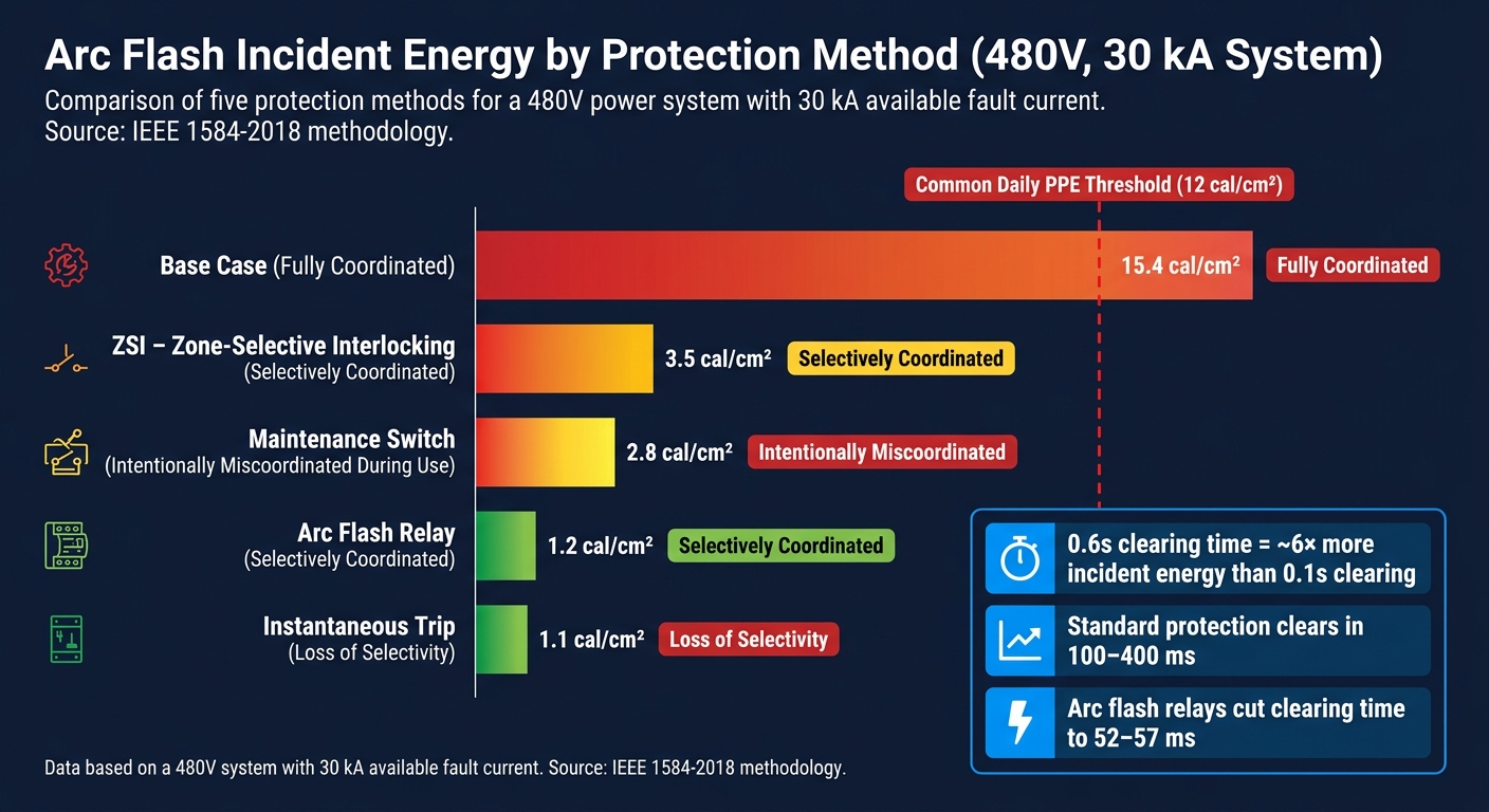
Arc Flash Incident Energy by Protection Method: 480V System at 30 kA
Setting Changes That Improve Speed Without Losing All Selectivity
Once you know that clearing time drives incident energy, the next step is simple: cut the clearing time without giving up needed selectivity.
One common move is to reduce unnecessary time delays on upstream devices. That can shorten fault-clearing time in a meaningful way without wrecking coordination across every feeder.
Using an instantaneous pickup setting is where things get tricky. It can meet NEC 240.87's arc energy reduction requirement, but it can also create unsafe trip overlap for high-level faults downstream of feeder circuit breakers. In plain terms, the breaker may trip fast, but not always in the way you want. Every setting change needs a coordination review before anything is changed in the field.
If setting changes don't get you far enough, faster methods such as breaker-to-breaker communication and temporary protection modes can help.
Zone-Selective Interlocking, Maintenance Switches, and Arc-Flash Detection
Zone-Selective Interlocking (ZSI) uses communication between breakers. If the main breaker sees a fault and gets no restraint signal from a downstream device, it trips at once. That helps clear bus faults faster.
Maintenance switches let a worker place a relay into a faster setting during energized work. This lowers risk for that task, but the tradeoff is clear: protection is intentionally miscoordinated while the switch is active.
Arc-flash detection relays take a different approach. They use both current monitoring and light sensing to detect the flash itself, then send a fast trip signal. Standard protection systems usually need 100 to 400 msec to detect an arc flash and open the breaker. Arc-flash detection relays can reduce that to 52 to 57 msec.
The differences stand out when the same fault is tested with different mitigation methods. In a 480 V case study with 30 kA available fault current, the results looked like this:
| Protection Method | Incident Energy (cal/cm²) | Coordination Status |
|---|---|---|
| Base case | 15.4 | Fully Coordinated |
| ZSI | 3.5 | Selectively Coordinated |
| Maintenance Switch | 2.8 | Intentionally miscoordinated during use |
| Arc Flash Relay | 1.2 | Selectively Coordinated |
| Instantaneous trip | 1.1 | Loss of selectivity |
Data based on a 480 V system with 30 kA available fault current.
When Partial Coordination Is an Acceptable Safety Decision
Sometimes engineers make a deliberate call to accept less selectivity. If incident energy is so high that people cannot work safely, even with full PPE, then perfect coordination stops being the top priority.
If the incident energy for the task stays too high, intentional miscoordination may be the safer option. But it should be treated as temporary, documented, and tied to a clear time limit. This isn't something to leave vague or open-ended.
After a strategy is picked, the settings need to be checked against actual system data and documented before release.
Study Inputs, Implementation, and Validation
After you pick a mitigation method, check it against current system data before you change any settings.
Data Needed for a Reliable Review
A relay study is only as good as the data behind it. So before you touch the settings, make sure the model matches the system as it stands today.
Gather current one-lines, transformer data, conductor data, and all source fault-current contributions. That includes utility, generator, and tie-breaker setups. Also confirm that the digital relays support custom TCCs and light-sensing pickup settings. If the system uses Zone-Selective Interlocking (ZSI), verify ZSI communication latency. Modern digital systems usually list ≤ 8 ms. Then use a coordination program to model the actual relay settings before anything goes live.
Good inputs decide whether faster settings will lower incident energy without causing coordination problems.
How Setting Changes Are Tested and Documented
After the study is done, review the proposed changes against the system’s protection goals before putting them in place. Protection, coordination, and arc-flash performance should be tested together, not one at a time.
Put changes in place through controlled procedures that line up with NFPA 70E, and verify incident energy against IEEE 1584-2018. Include a failure-mode check for lost relay communication. The final package should include:
- Revised settings files
- Updated arc-flash labels
- The final study report
Once the settings are approved, verify them in the field before returning the equipment to service.
What to Verify After Changes Go Live
After commissioning, verify the settings in the field. Check relay settings, label values, and ZSI links at the equipment. This confirms that the new settings produce the lower clearing time and labeling the study predicted.
Re-run the study after any equipment or source change.
Conclusion: Balancing Coordination and Arc Flash Protection
Good relay coordination keeps the lights on. But it does not automatically keep workers safe.
Here’s the tension: the time delays that help preserve selectivity also make an arc fault last longer. And as fault-clearing time goes up, incident energy goes up with it. So a system can be perfectly coordinated on paper and still leave workers facing high arc-flash risk.
That doesn’t mean coordination should be tossed out. The aim is to cut clearing time without giving up the selectivity the system needs. As the earlier sections showed, maintenance mode, Zone-Selective Interlocking (ZSI), and arc-flash relays each offer a different tradeoff between speed and selectivity.
The case study put that tradeoff into plain view. Faster clearing pushed incident energy below the common 12 cal/cm² daily PPE threshold without fully giving up coordination. It also showed that instantaneous pickup, maintenance mode, ZSI, and arc-flash relays can all reduce incident energy, but each one affects selectivity in a different way.
The best fit depends on a few practical factors:
- voltage
- fault current
- equipment age
- required selectivity
That’s why post-change validation isn’t optional. Any setting change needs an updated arc-flash study.
FAQs
Why can a coordinated system still have high arc-flash energy?
A system can be well coordinated and still produce high arc-flash energy. The big reason is fault clearing time.
If a fault takes longer to clear, the arc lasts longer. And when arc duration goes up, incident energy goes up with it.
This often happens when instantaneous tripping is not used. Without it, the device may wait longer before it trips, which gives the arc more time to keep burning.
Which relay settings have the biggest impact on incident energy?
The relay settings that affect incident energy the most are trip time delays. The two big ones are the instantaneous trip (IT) setting and the short-time delay (STD).
Here’s the simple version: faster trip times mean lower arc flash incident energy.
That’s because incident energy builds up over time. If the relay clears the fault sooner, the arc has less time to keep burning. Less burning time means less energy released at the worker’s position.
When is reduced selectivity worth the safety tradeoff?
Reduced selectivity is worth the safety tradeoff when it cuts arc flash incident energy by a large margin, especially in switching or maintenance modes where personnel safety matters more than system reliability.


