Circuit Breaker Coordination Basics
When a fault occurs in an electrical system, only the breaker closest to the issue should trip. This ensures the rest of the system stays operational. Known as circuit breaker coordination or selective coordination, this process involves adjusting overcurrent protective devices (OCPDs) to isolate faults effectively. Without proper coordination, even minor faults can cause widespread outages, disrupt operations, and damage critical systems.
Here’s what you need to know:
- Purpose: Minimize disruptions by ensuring only the nearest breaker trips during a fault.
- Key Tools: Engineers use Time-Current Characteristic (TCC) curves to set Coordination Time Intervals (CTI) and adjust breaker settings.
- Applications: Required by the National Electrical Code (NEC) for systems like emergency power (Article 700.32), elevators (Article 620.62), and healthcare facilities (Article 517.31(G)).
- Challenges: Instantaneous trip overrides, high fault currents, and balancing arc flash safety with coordination.
Proper coordination is critical for maintaining system reliability, especially in medium-voltage setups like hospitals, data centers, and manufacturing plants. Advanced methods like Zone Selective Interlocking (ZSI) and current-limiting breakers help address these challenges.
Bottom line: Circuit breaker coordination ensures faults are isolated to the smallest possible area, keeping power systems reliable and compliant with NEC standards.
What Is Circuit Breaker Coordination?
Definition and Core Concepts
Circuit breaker coordination, often called selective coordination, involves setting up overcurrent protective devices (OCPDs) so that only the device closest to a fault responds. According to NEC Article 100, this means isolating an overcurrent situation by choosing the right OCPDs and adjusting their settings or ratings to handle all faults and tripping times. Engineers rely on Time-Current Characteristic (TCC) curves - logarithmic plots showing current versus time - to establish a Coordination Time Interval (CTI). For electronic relays, this interval is typically 0.2–0.3 seconds, while for electromechanical relays, it’s 0.3–0.4 seconds. In medium-voltage systems, this process often involves protective relays working alongside circuit breakers.
This approach ensures that each device operates independently, which is key to distinguishing selective coordination from series ratings.
Selective Coordination vs. Series Ratings
Selective coordination focuses on system reliability by ensuring only the breaker nearest to a fault trips, minimizing disruptions. In contrast, series-rated systems (as defined by NEC 240.86) depend on an upstream device to enhance a downstream breaker’s interrupting capacity. This setup can cause both breakers to trip simultaneously during high-fault scenarios.
Breaker Hunters, Inc. explains, "Series ratings address interrupting ratings - not selectivity. In fact, they often conflict with selective coordination requirements."
For example, in a system lacking selective coordination, a high fault current might trip both upstream and downstream breakers, potentially leading to unnecessary system-wide outages. This highlights why selective coordination is essential for maintaining system functionality, especially in medium-voltage setups. The NEC specifically requires selective coordination for life-safety systems - like emergency power, standby systems, elevators, and healthcare facilities - to ensure that only the affected circuit is de-energized, leaving the rest of the system operational.
sbb-itb-501186b
Why Circuit Breaker Coordination Matters in Medium-Voltage Systems
Critical Infrastructure Applications
Medium-voltage systems, operating between 1 kV and 38 kV, are the backbone of critical facilities where power interruptions simply can't be tolerated. Think about hospitals, data centers, or manufacturing plants - these places rely on steady, uninterrupted power to function. To ensure this, the National Electrical Code (NEC) enforces selective coordination requirements for emergency systems (NEC 700.32), legally required standby systems (NEC 701.32), and critical operations power systems (NEC 708.54). In healthcare facilities, the rules are even stricter, as outlined in NEC 517.31(G).
"A sudden power failure will have a significant impact on operations, especially in a critical environment." - Keith Lane, CEO of Lane Coburn & Associates
For example, in hospitals, losing power to fire pumps, emergency lighting, or elevators during a crisis can create immediate and dangerous safety issues. Similarly, data centers are high-stakes environments where power loss to server racks or cooling systems can result in corrupted data and even regulatory violations, as highlighted in NEC 645.27 for Critical Operations Data Systems. These guidelines are vital to protect both equipment and operational continuity, emphasizing why proper coordination is so important.
Risks of Poor Coordination
When circuit breakers aren't properly coordinated, a single fault in a downstream circuit can ripple through the system, causing unnecessary trips in unaffected circuits. This isn't just a compliance issue - it also increases fault energy and extends clearing times, which can put added stress on transformers and speed up insulation aging. Worse, if upstream breakers trip unnecessarily, it can lead to widespread outages, production halts, and costly equipment damage.
Failing to meet NEC standards for emergency and standby systems can result in failed inspections and legal liabilities. Engineers are often tasked with a tricky balancing act: they need to set trip thresholds high enough to avoid nuisance trips, like those caused by motor inrush currents, but low enough to protect equipment from prolonged faults. Adding time delays to improve coordination can further complicate things by increasing arc-flash incident energy. Advanced solutions, such as Zone Selective Interlocking (ZSI), help resolve this tension by maintaining both safety and system selectivity.
"Isolating a fault condition to the smallest area possible is essential in providing the most reliable electrical system with maximum uptime for your facility." - Keith Lane, President/CEO, Lane Coburn & Associates
Core Principles of Circuit Breaker Coordination
Downstream vs. Upstream Device Behavior
At its core, circuit breaker coordination relies on a straightforward rule: the device closest to the fault (downstream) should trip first, while upstream breakers act as backup and remain closed unless absolutely necessary. This ensures the faulted section is isolated quickly, keeping the rest of the system running smoothly.
Downstream breakers are designed to act faster because their tripping mechanisms are lighter and more responsive than those of larger upstream breakers. For coordination to work, the downstream breaker must fully interrupt the fault before the upstream breaker begins its unlatching process, which is when it starts separating its contacts irreversibly. Without proper coordination, a larger upstream breaker (e.g., 400 A) might unlatch at fault levels as low as 1,500 A (based on a 5× setting with a 25% tolerance band), even if a smaller downstream breaker (e.g., 90 A) is also trying to clear the fault.
Engineers assign priority levels to devices in the system. For example, Level 1 devices protect main circuits with multiple feeders, where a trip would cut power to several branches and require strict selectivity. On the other hand, Level 2 devices protect individual loads, so the same equipment is disconnected regardless of which device trips.
Time-Current Curve Analysis
Time-current curves (TCCs) are a visual tool engineers use to ensure proper coordination by illustrating how quickly each device reacts to various fault currents. These curves are plotted on log-log axes, with current on the X-axis and time on the Y-axis, and they highlight the timing differences between downstream and upstream devices. A critical parameter here is the Coordination Time Interval (CTI) - the time gap between the curves of the downstream and upstream devices. Industry standards generally recommend a CTI of 0.2–0.3 seconds for relays and about 0.1 seconds for low-voltage breakers and fuses to account for manufacturing tolerances.
"If a point is discovered where an upstream device opens before the downstream device opens, that system is not selectively coordinated." - David G. Loucks, P.E., Eaton Corp.
Overlapping TCCs indicate poor selectivity, meaning multiple devices could trip simultaneously, potentially leading to unnecessary power outages. Instead of showing a single line, TCCs are often displayed as a "band", representing the range from the minimum pickup to the total clearing time. These bands are divided into three regions: the thermal (long-time) region for overloads, the short-time region for planned delays, and the instantaneous region for high-magnitude faults. To ensure accuracy, engineers rely on manufacturer datasheets for precise TCC data.
Setting Thresholds and Delays
Once TCCs define how devices should respond, engineers fine-tune current thresholds and delays to prevent unwanted or simultaneous tripping. The instantaneous trip (IT) setting determines the multiple of the breaker's full load rating at which it trips without delay. This means coordination is effective only for currents below the upstream breaker's instantaneous pickup level. Short-time delay (STD) settings allow upstream breakers to wait briefly, giving downstream devices a chance to clear the fault first. Some low-voltage breakers even offer STD functionality without an instantaneous override.
Manufacturing tolerances, which can range from ±10% to ±25% depending on the trip setting and manufacturer, are accounted for in TCCs. To maintain proper coordination, engineers set IT levels and STD settings to ensure downstream breakers act first, leaving at least 0.3 seconds of separation to accommodate these tolerances.
"The first breaker to open will likely be the breaker closest to the fault because smaller breakers closer to the fault will have tripping mechanisms with lower mass compared to larger upstream breakers." - David G. Loucks, P.E., Eaton Corp.
When designing a coordination scheme, the process starts at the load and works upstream toward the power source. This "load outward" approach ensures branch devices clear faults quickly, while upstream devices incorporate intentional delays to allow downstream breakers time to respond. Field verification, such as time-to-trip testing, is crucial to confirm that actual breaker settings align with the coordination study. These steps help ensure faults are isolated efficiently, keeping the system operational and compliant with NEC standards.
Circuit Breaker Selective Coordination Common Questions and Misconceptions
Coordination Methods and Techniques
To ensure that only the nearest breaker to a fault trips, engineers use a few reliable coordination methods. These techniques are chosen based on the system's needs and the levels of fault current, balancing safety, cost, and system reliability.
Time-Delayed Tripping
This method uses the time-current curve to differentiate between upstream and downstream devices. The curve is divided into long, short, and instantaneous regions. In the short-time region, intentional delays - ranging from about 0.1 to 0.5 seconds - give downstream breakers time to clear faults. For high-magnitude faults, the instantaneous region reacts faster, tripping in less than 0.01 to 0.1 seconds.
However, many molded-case and insulated-case breakers include a fixed instantaneous override to protect themselves during high fault currents. According to the IEEE 1015-2006 "Blue Book", "Selective coordination is limited to currents below the instantaneous pickup of the lineside circuit breaker". If fault currents exceed the upstream breaker's instantaneous threshold, both upstream and downstream devices may trip simultaneously. To avoid this, it's crucial to check override thresholds in manufacturer datasheets when designing the system.
Zone-Selective Interlocking (ZSI)
Zone-Selective Interlocking is designed to address the limitations of instantaneous overrides. This method uses communication signals between breakers to delay upstream tripping. When a downstream breaker detects a fault, it signals the upstream breaker to follow its programmed delay. If the upstream breaker detects a fault without receiving this signal, it trips immediately, indicating the fault is within its own zone.
ZSI is particularly useful for meeting NEC 240.87 requirements, which call for arc-energy reduction methods in breakers rated 1,200 A or higher. While this approach adds complexity and cost - requiring compatible breakers and interconnection wiring - it’s a solid choice for critical systems where safety and uptime are non-negotiable. For setups where communication-based delays aren't practical, other methods might be more suitable.
Cascading with Current-Limiting Breakers
Cascading, also called series ratings, uses an upstream current-limiting breaker to lower the peak fault current and reduce the energy passed to downstream devices. This allows the use of downstream breakers with lower interrupting ratings, potentially cutting equipment costs. However, cascading sacrifices selectivity, making it unsuitable for systems that demand strict coordination. In these setups, both upstream and downstream breakers may trip simultaneously, causing wider outages. This limitation makes cascading less ideal for critical applications like emergency systems or healthcare facilities, where selective coordination is essential.
Common Challenges in Circuit Breaker Coordination
This section dives into the practical struggles often faced in circuit breaker coordination. By pinpointing where coordination tends to falter, engineers can design protection schemes that are more dependable from the outset.
Instantaneous Override Issues
One major hurdle is instantaneous trip overrides. Many molded-case and insulated-case circuit breakers come with a factory-set, fixed instantaneous trip setting. This feature is designed to protect the breaker during extreme fault currents but lacks adjustability in most cases.
When a fault current surpasses the upstream breaker's instantaneous threshold, the breaker unlatches in less than 0.01 seconds. This mechanical process is irreversible. Even if a downstream breaker clears the fault quickly, the upstream breaker will still disconnect unaffected circuits. Compounding this issue, standard time-current curves only go down to 0.01 seconds, leaving the unlatching behavior unrepresented and creating a misleading sense of coordination.
To mitigate this, low-voltage power circuit breakers are recommended for critical upstream positions. These breakers can be ordered without a fixed instantaneous trip, enabling full coordination through short-time delay settings. For existing systems, increasing the instantaneous trip setting from 5× to 10× the breaker rating can also help maintain coordination.
Another issue arises with transformer inrush current, which can spike to 12× full load for 0.1 seconds or 25× for 0.01 seconds during energization. If the primary breaker's instantaneous setting is too sensitive, it might trip during normal startup. For K-rated transformers (K13 or higher), multiplying the input full load amps by 125% and selecting the next standard breaker size can prevent these nuisance trips.
Beyond instantaneous overrides, high fault current scenarios pose additional challenges to coordination.
High-Fault Current Scenarios
High fault currents can push multiple breakers into their instantaneous regions at the same time. During the first half-cycle, the instantaneous peak can reach 2.3 times the available RMS bolted-fault current. In poorly coordinated systems, a significant fault - such as 6,500 A on a 100‑A branch circuit - can unnecessarily trip a 1,200‑A main breaker, cutting off power to unaffected parts of the facility.
Standard time-current curves don't fully capture these high-level behaviors. Instead, manufacturer coordination tables are more accurate, as they reflect real-world performance beyond the curves' intersection points. Using current-limiting fuses or breakers can also help by reducing peak let-through currents. For instance, a 200‑A current-limiting fuse can lower a potential 100,000‑A fault to a 20,000‑A peak. When selecting fuses, follow manufacturer-recommended ratios - like 2:1 for UL Class J to RK‑1 fuses - to maintain selectivity.
Regulatory requirements further complicate coordination efforts.
NEC 240.87 Compliance

For breakers rated 1,200 A and above, NEC 240.87 mandates arc energy reduction methods to limit fault-clearing times. This requirement aims to reduce arc flash hazards, which account for about 10 incidents daily in the United States. Zone-selective interlocking (ZSI) is a widely used solution in these cases.
Ground fault protection adds another layer of complexity. NEC restricts ground fault settings to 1,200 A maximum, regardless of breaker size, and limits time delays to 1 second for fault currents of 3,000 A or more. In healthcare facilities, a minimum delay of 6 cycles (0.1 seconds) between different levels of ground fault protection is required. This narrow time frame makes it challenging to coordinate multiple levels of protection while balancing arc flash safety and system reliability, especially in medium-voltage setups.
"Settings that provide the optimum separation between the time current curves and isolate a fault to the smallest area possible may actually cause higher levels of arc flash energy." - Keith Lane, President and CEO, Lane Coburn & Assocs
How to Achieve Circuit Breaker Coordination
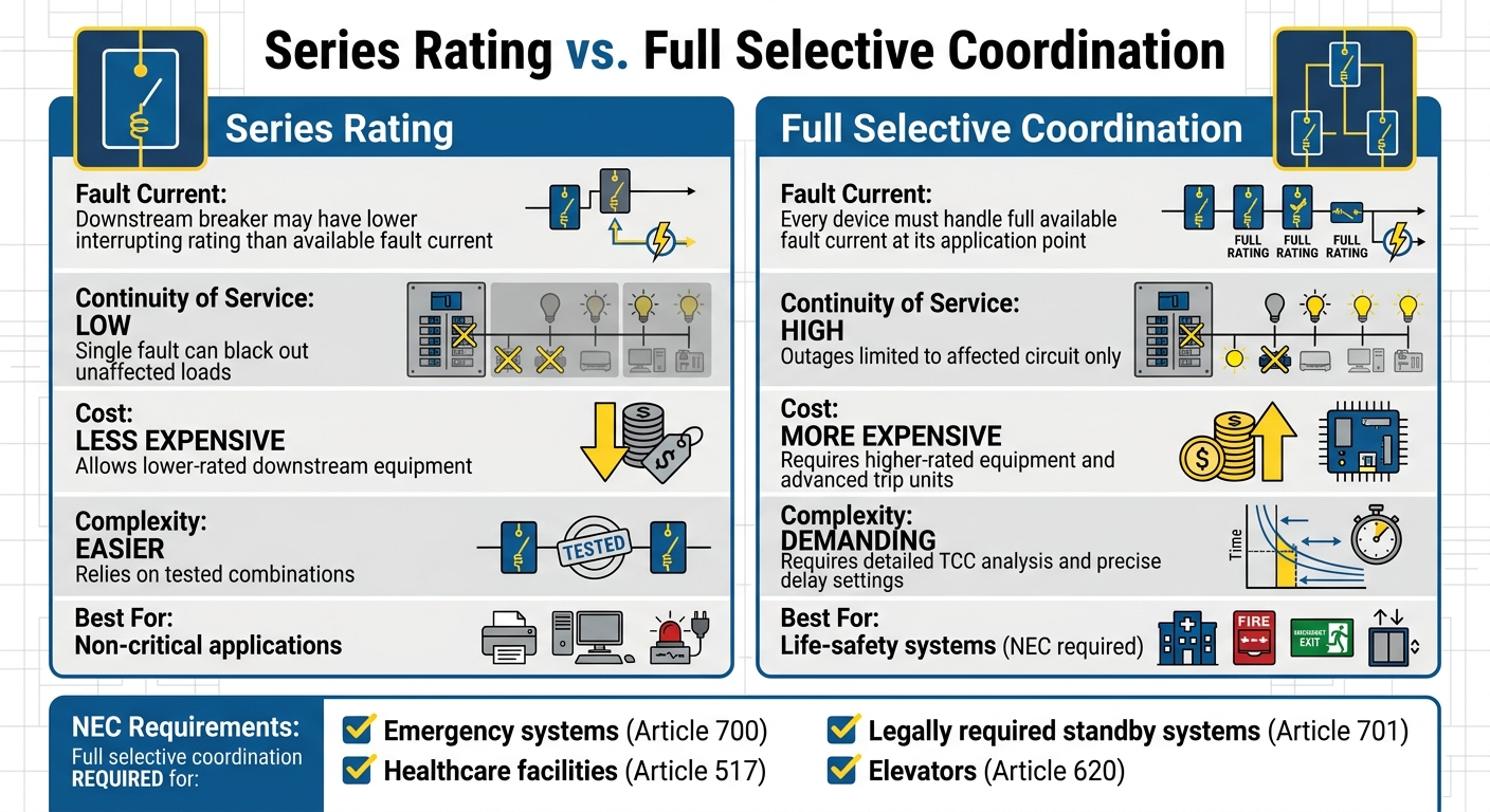
Selective Coordination vs Series Rating: Key Differences in Circuit Breaker Systems
To ensure effective circuit breaker coordination, start by gathering detailed data. A thorough one-line diagram is essential, along with key parameters like utility fault-duty, transformer impedance, generator subtransient reactance, and cable lengths. Before diving into coordination, perform short-circuit and load-flow analyses to identify critical fault and continuous current levels. This helps avoid over-engineering while ensuring coordination is only applied up to the maximum available fault level.
Using Coordination Tables and Software
Modern tools like SKM and ETAP have revolutionized coordination studies. These software platforms automate the creation of time-current curves (TCCs) across a wide range (0.01 to 1,000 seconds) and support various analyses, including short-circuit, load flow, and arc flash calculations. By creating a single-line diagram, engineers can reuse it for multiple studies, saving time and effort.
Manufacturer-specific software, while often free, typically includes only that manufacturer's device libraries. For projects involving devices from multiple manufacturers, generic software becomes indispensable.
However, when TCC curves overlap in the instantaneous region, graphical methods might not suffice. In such cases, manufacturer coordination tables are crucial. Eduard Pacuku, PE at Jacobs, explains their importance:
"When other methods fail, using these protective-device coordination tables is the only reliable way to get the job done".
These tables are based on laboratory testing and help confirm coordination at high-fault levels, even when TCC curves suggest otherwise. They're especially critical for molded case circuit breakers (MCCBs), as they provide insight beyond curve intersections.
Series Rating vs. Full Selective Coordination
Choosing between series rating and full selective coordination depends on cost, complexity, and the desired level of system reliability. Here's a quick comparison:
| Feature | Series Rating | Full Selective Coordination |
|---|---|---|
| Fault Current | Downstream breaker may have a lower interrupting rating than available fault current | Every device must handle the full available fault current at its application point |
| Continuity of Service | Low; a single fault can black out unaffected loads | High; outages are limited to the affected circuit |
| Cost | Less expensive; allows lower-rated downstream equipment | More expensive; requires higher-rated equipment and advanced trip units |
| Complexity | Easier to implement; relies on tested combinations | Demands detailed TCC analysis and precise delay settings |
Eduard Pacuku highlights the trade-off:
"Selective coordination makes for a more expensive electrical system. Because NEC is primarily interested in the safety of humans, it requires selective coordination only in systems that directly affect life safety".
The National Electrical Code (NEC) mandates full selective coordination for specific systems, including emergency systems (Article 700), legally required standby systems (Article 701), healthcare facilities (Article 517), and elevators (Article 620).
Verification Across Voltage Levels
Effective coordination extends beyond a single voltage level. When integrating transformers, breakers, and equipment operating at different voltages, plot all device curves - including transformer thermal damage curves, cable curves, and motor starting curves - on the same TCC. This ensures protection integrity across the entire system.
Coordination time intervals (CTI) also vary by device type. For medium-voltage systems, static (electronic) relays need a separation of 0.12 to 0.3 seconds, while older electromechanical relays require 0.3 to 0.4 seconds. When pairing a fuse with a static relay, maintain at least 0.12 seconds of separation; with an electromechanical relay, increase this to 0.22 seconds.
Although many coordination studies begin downstream and work upward, utility restrictions often require starting at the main substation (upstream) and moving downstream. This approach avoids conflicts with utility-imposed limits, ensuring a well-coordinated system that meets all requirements. Verifying across voltage levels underscores the importance of detailed studies, especially in complex, multi-voltage setups.
Conclusion
Circuit breaker coordination plays a crucial role in ensuring safety, system reliability, and compliance. By making sure that only the device closest to a fault trips, coordination minimizes disruptions, prevents widespread outages, and keeps critical systems running smoothly.
Key principles like Time-Current Characteristic (TCC) analysis and Zone Selective Interlocking (ZSI) are fundamental to protecting both equipment and people. As Edvard Csanyi, Founder of EEP, explains:
"Isolation of a faulted circuit from the remainder of the installation is critical in today's modern electrical systems. Power blackouts cannot be tolerated".
Proper coordination starts at the design phase. Once components like switchboards and motor control centers are installed, fixing coordination issues becomes much harder. This underscores the importance of using accurate TCC analysis and cross-checking settings with manufacturer coordination tables, especially when curve overlaps occur.
Coordination isn't a one-and-done task - it requires ongoing attention. The 2023 NEC mandates selective coordination to be re-evaluated whenever overcurrent protective devices are replaced or system modifications are made. As Distributed Energy Resources (DERs) alter fault levels, updated studies become essential. Regular reviews and updates ensure that systems remain protected and compliant over time.
Whether dealing with medium-voltage switchgear or low-voltage panels, the goal is always the same: isolate faults, safeguard equipment, and maintain power continuity. With the right planning and tools, achieving reliable coordination is entirely possible.
FAQs
How can I tell if my breakers are selectively coordinated?
To ensure selective coordination, the breaker closest to the fault must trip first. This isolates the problem while leaving the rest of the system unaffected. Achieving this requires conducting a coordination study, which involves analyzing time-current characteristic curves (TCCs) to confirm that device settings are correctly configured. Beyond this, it's essential to review the system design and carry out tests or simulations. These steps help verify that only the nearest breaker reacts to a fault, ensuring both system reliability and safety.
What should I do when instantaneous trip overrides prevent coordination?
If instantaneous trip overrides are causing coordination issues, take a closer look at the settings for the instantaneous trip or hardware override levels. Make adjustments as necessary to align with proper coordination, using the guidelines outlined in circuit breaker manuals or other technical references. Always consult the manufacturer's documentation for detailed instructions to ensure system protection isn't compromised.
How can I balance selective coordination with arc-flash safety requirements?
Balancing selective coordination with arc-flash safety means designing electrical systems that can isolate faults efficiently while minimizing arc-flash hazards. The goal is to ensure that downstream circuit breakers trip faster than upstream ones when faults occur, limiting the impact to only the affected area.
To achieve this, engineers often rely on adjustable trip settings and perform detailed system studies, such as arc-flash analyses and coordination studies, to fine-tune performance. Following industry standards like the NEC (National Electrical Code) and NFPA (National Fire Protection Association) ensures proper implementation, promoting both safety and system reliability.