Generator Sync Alarms: Key Features
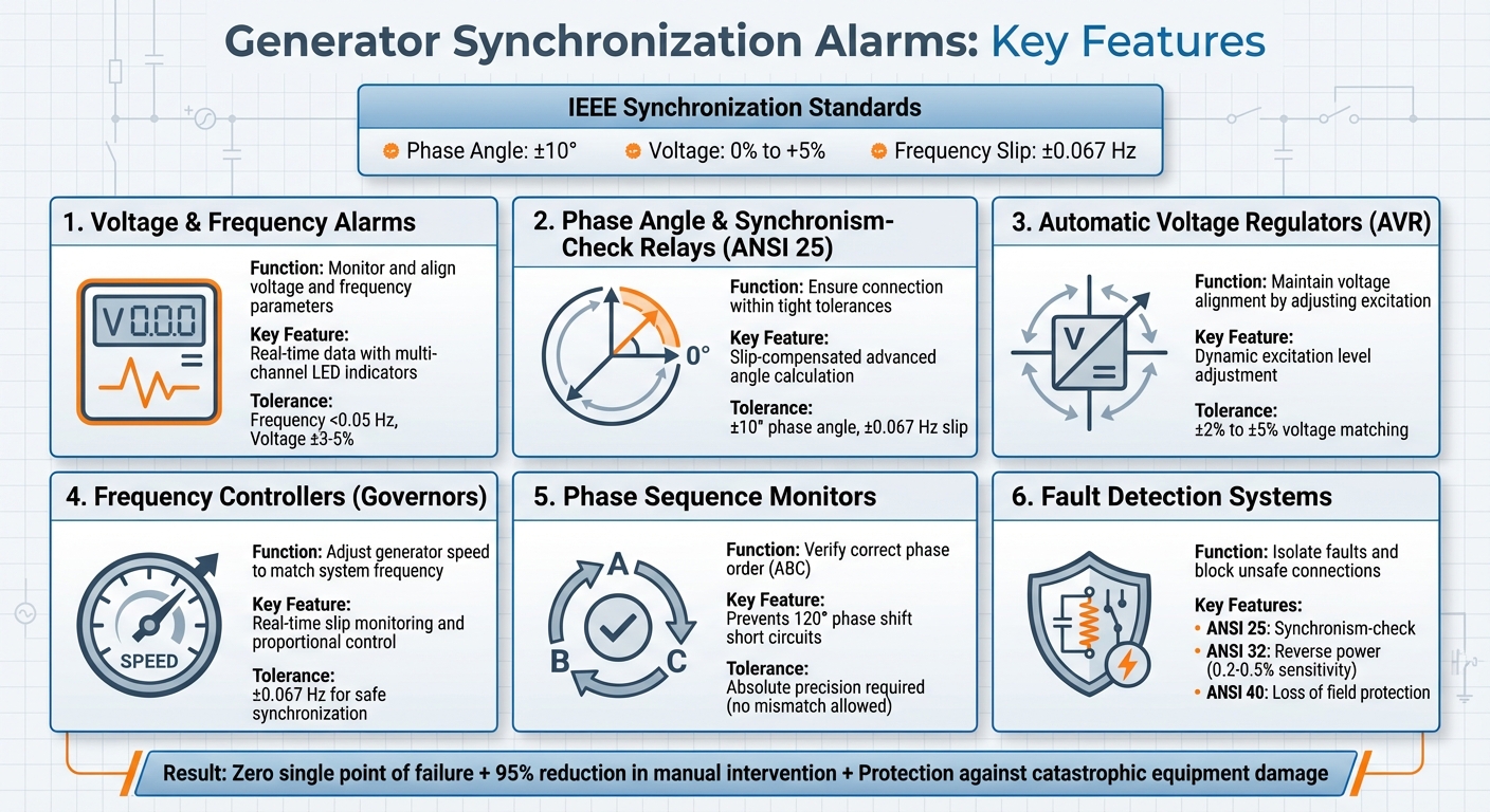
Generator synchronization alarms are critical for ensuring safe and reliable connections between generators and live power systems. They monitor voltage, frequency, phase angle, and phase sequence to prevent catastrophic failures. Missteps during synchronization can cause severe damage, such as short circuits, stator winding destruction, or rotor shaft damage. Here's what you need to know:
- Voltage & Frequency Alarms: These monitor and align voltage and frequency parameters, preventing mismatches that could harm equipment. Advanced systems provide real-time data and remote monitoring for quick adjustments.
- Phase Angle & Synchronism-Check Relays: These ensure the generator connects within tight tolerances, typically ±10° phase angle and ±0.067 Hz slip, avoiding damaging transient currents.
- Automatic Voltage Regulators (AVRs): AVRs maintain voltage alignment by dynamically adjusting excitation levels, preventing reactive power surges during synchronization.
- Frequency Controllers: These adjust the generator's speed to match the system frequency, ensuring smooth synchronization and reducing mechanical stress.
- Phase Sequence Monitors: These verify the correct phase order (ABC), preventing short circuits caused by mismatched sequences.
- Fault Detection Systems: Protective relays (e.g., ANSI 25, 32, 40) isolate faults, blocking unsafe connections and safeguarding equipment.
Modern systems integrate these alarms with automated controls for precise synchronization, reducing human error and ensuring system stability. Facilities benefit from features like remote diagnostics, detailed alarm logs, and seamless integration with SCADA systems.
Bottom line: Generator sync alarms are indispensable for protecting equipment, maintaining grid stability, and ensuring uninterrupted power.
6 Critical Generator Synchronization Alarm Systems and Their Functions
Generator Synchronization (Full Lecture)
sbb-itb-501186b
1. Voltage and Frequency Alarms
Voltage and frequency alarms act as the first line of defense in generator synchronization. These systems continuously monitor key parameters like voltage magnitude, frequency, and slip rate to ensure the incoming generator aligns perfectly with the live bus before connection. Even minor mismatches can lead to equipment damage or system disruptions, making this constant oversight essential. These alarms not only detect potential issues but also enable quick responses through advanced monitoring tools.
Real-time monitoring capabilities
Modern synchronizing panels are equipped with real-time features like multi-channel LED indicators, synchroscopes, and display feedback, which provide operators with instant updates on whether a generator is running "fast" or "slow" compared to the grid. These visual aids are paired with automated sensors that feed data directly into control systems for immediate adjustments. For facilities managing multiple generators, IoT-enabled panels take things a step further by transmitting alarm data to mobile devices or remote control centers. This allows technicians to identify and address problems without needing to be physically present.
In 2025, a pharmaceutical plant in Hyderabad showcased this capability by installing a Synchro Electricals panel for four generators. Over 12 months, the system achieved zero unplanned shutdowns and reduced diesel costs by 25% through optimized load sharing and synchronization.
Accuracy in detecting synchronization issues
Precision is critical when it comes to detecting synchronization mismatches. According to IEEE Standards C50.12 and C50.13, generators must synchronize within an angle of ±10 degrees, a voltage range of 0 to +5%, and a slip of ±0.067 Hz. Advanced systems aim for even tighter tolerances, targeting frequency differences below 0.05 Hz and voltage matching within ±3% to ±5% at the point of closure.
Modern microprocessor-based alarms directly measure slip, addressing the delays often seen with older induction disk relays. This real-time measurement prevents "late-close" scenarios, where the breaker connects after the ideal 0° phase angle, ensuring smoother operation.
Michael J. Thompson of Schweitzer Engineering Laboratories, Inc., highlights the importance of automation in synchronization: "The improved consistency provided by an automatic synchronizer can limit the opportunity for this cumulative damage over the course of many synchronizations".
System integration and automation
Modern systems take precision a step further by integrating seamlessly with automated controls. Voltage and frequency alarms are designed to work in tandem with automated systems, reducing the chance of human error. Digital control modules from manufacturers such as Cummins PowerCommand, Woodward, and DEIF use real-time data to automatically adjust engine speed and excitation. These systems also calculate advance angles and use permissive logic to ensure breaker closure occurs at nearly zero phase alignment, compensating for the 2–5 cycle delay common in mechanical breakers.
This level of automation proved essential at an oil refinery in Gujarat, where custom-built synchronization panels with remote diagnostics ensured 100% uptime during audits while managing a large generator network.
Protection and fault isolation features
To complement monitoring and automation, fault isolation mechanisms provide an added layer of protection. When synchronization parameters exceed acceptable limits, voltage and frequency alarms trigger protective actions. These alarms integrate with relay systems such as ANSI 25 (sync-check), ANSI 32 (reverse power), and ANSI 40 (loss of field) to ensure thorough fault isolation. For instance, if a generator attempts to connect with mismatched parameters, the sync-check relay blocks breaker closure, preventing a dangerous out-of-sync short circuit.
Reverse power protection is another important feature, activating when synchronization faults cause the generator to act as a motor. These systems are highly sensitive, with settings ranging from 0.2% to 0.5% of the unit's rating. Regular quarterly load tests are essential to verify that these alarms and safety shutdowns function correctly under simulated synchronization conditions.
2. Phase Angle and Synchronism-Check Relays
Phase angle and synchronism-check relays (Device 25) play a key role in ensuring safe connections to the grid. These relays continuously monitor three critical parameters: voltage magnitude, frequency difference (slip), and phase angle between the incoming generator and the live bus. The breaker is allowed to close only if all three measurements stay within pre-set limits. This prevents out-of-sync connections that could damage equipment or disrupt the system. By expanding on earlier voltage and frequency alarm systems, these relays provide unmatched precision in phase alignment, setting the stage for their advanced real-time capabilities.
Real-Time Monitoring Capabilities
Accurate, real-time monitoring is essential for maintaining grid stability during synchronization. Modern microprocessor-based relays excel in this area by directly measuring voltage, frequency, and phase angle in real time. Unlike older systems that relied on time-delay settings, these relays calculate slip directly. Voltage differences between the generator and bus are measured using direct RMS methods, which are far more reliable than the vector sum approach used in electromechanical relays.
These advanced relays also track the phase relationship between the generator and system, keeping it within a tight range - typically 0 to ±10 degrees. They can also identify specific states, such as "live generator/dead bus" or "dead generator/live bus", allowing for black-start scenarios while avoiding accidental energization of a faulted bus. Many facilities enhance this functionality by pairing relays with computer-based "soft synchroscopes", which provide operators with detailed digital visualizations far superior to traditional analog displays.
Accuracy in Detecting Synchronization Issues
Precision is critical when synchronizing generators with live systems. Even a small phase misalignment - say, 30° - at breaker closure can lead to damaging transient currents. Modern relays are designed to keep phase differences under 10°–20°, frequency deviations within 0.1–0.2 Hz, and voltage mismatches within 2–5%.
A standout feature of microprocessor-based relays is their ability to calculate a slip-compensated advanced angle. This accounts for the mechanical delay in circuit breaker closure (typically 2–5 cycles), ensuring the breaker closes at the precise zero-degree point. For instance, with a slip of 0.05 Hz and a 5-cycle delay, the relay calculates an advanced angle of 1.5 degrees. This level of precision protects critical generator components by preventing issues like "late-close" scenarios, where contacts might weld due to excessive current.
"The main advantage of an automatic synchronizer over an operator is that the device can more consistently close the breaker at the precise correct moment." - Michael J. Thompson, Schweitzer Engineering Laboratories, Inc.
System Integration and Automation
Modern synchronism-check relays integrate seamlessly with automated control systems. Using logic-based selection and isolated I/O terminals, these relays provide a "go/no-go" signal to the governor and automatic voltage regulator (AVR), ensuring all parameters meet strict tolerances before the breaker closes.
For critical applications, facilities often implement two-level supervision. The first level handles manual or automatic adjustments, while the second uses a multifunction synchronism-check relay to add an extra layer of protection by controlling the permissive contact in series with the breaker’s closing coil. Remote I/O modules and fiber-optic links further enhance these systems, enabling synchronizers to be placed near remote breakers. This reduces the signal degradation associated with long VT circuit runs and lowers installation costs. Some advanced synchronizers can even handle slip as low as 0.0001 Hz.
Protection and Fault Isolation Features
Synchronism-check relays are vital for blocking breaker closure when parameters exceed safe limits. This protection is essential to avoid catastrophic failures, such as those caused by mismatched phase sequences (e.g., ABC vs. ACB), which can lead to a direct short circuit.
These relays also feature dead-bus logic with operator-controlled permissives to prevent synchronization errors due to issues like blown bus VT fuses. When configured with precise advanced angle calculations tailored to the specific breaker’s closing time (around 100 milliseconds), these systems effectively prevent transient torques that could damage generator shafts, stator windings, or step-up transformers.
3. Automatic Voltage Regulators (AVR)
Automatic Voltage Regulators (AVRs) play a key role in linking a generator's output to the grid by ensuring voltage alignment during synchronization. While phase and frequency monitoring are essential, AVRs focus specifically on maintaining voltage compatibility - critical for a safe and stable connection. They continuously monitor the voltage at the generator terminals and dynamically adjust the alternator's excitation current to match the bus bar voltage. Without this alignment, attempting a connection could result in dangerous reactive power surges.
Real-Time Monitoring Capabilities
Modern AVRs use digital technology to track voltage variations against a stable reference point. During synchronization, they receive input from auto-synchronizers to fine-tune excitation levels, ensuring the generator voltage stays within a ±2% to ±5% tolerance range. Many advanced AVRs go a step further, offering diagnostic features that provide real-time alerts for conditions like over-voltage, under-voltage, or excessive temperatures. In systems with multiple generators running in parallel, AVRs also monitor "voltage droop" to balance the reactive power load among units, which is crucial for maintaining system stability.
Accuracy in Detecting Synchronization Issues
Precise voltage matching is critical for safe synchronization. If the AVR permits a connection with even a slight mismatch, reactive power surges can occur, potentially leading to overheating. On the other hand, connecting at a voltage that’s too low can cause power to flow back into the generator, risking a "Loss of Field" (ANSI 40) relay trip. To meet industry standards, synchronization must occur within narrow voltage tolerances. Digital AVRs, with their ability to directly measure RMS voltage, respond much faster and more accurately than older electromechanical designs.
"The AVR is the component that makes generator power reliable, usable, and safe." - Depco Power Systems
System Integration and Automation
Digital AVRs simplify synchronization by automating critical adjustments, reducing reliance on manual intervention. Through interfaces, they receive "raise" or "lower" commands from auto-synchronizers, seamlessly integrating with control systems like Cummins PowerCommand or Woodward controllers. These microprocessor-based systems coordinate the AVR's actions with other synchronization parameters, eliminating the errors often associated with manual voltage matching using dual voltmeters. Advanced models also feature programmable settings and rapid response times, making them ideal for industrial applications where even minor voltage fluctuations can be disruptive.
Protection and Fault Isolation Features
AVRs are designed not only to monitor and adjust voltage but also to protect the synchronization process. Some models include an "automatic bypass" feature, which ensures power can flow directly if the AVR itself encounters a fault, preventing a total system shutdown. Additionally, AVRs work alongside synchronism-check relays to block breaker closures when voltage differences exceed safe thresholds. Regular calibration and inspection are essential to maintain their reliability. Proper enclosure mounting is another important factor, as it shields the AVR from environmental factors like moisture, dust, and electrical interference that could impair its function.
4. Frequency Controllers
Frequency controllers, often referred to as governors, are designed to adjust the speed of the prime mover so it aligns with the 60 Hz system frequency, working alongside voltage and phase checks. Their main job is to reduce frequency slip - the difference in angular velocity between the generator and the power system. Even small discrepancies in speed can place significant stress on the prime mover and may activate Reverse Power (ANSI 32) protection if the generator operates slower than the grid.
Real-Time Monitoring Capabilities
Modern frequency controllers continuously monitor frequency slip in real time, sending proportional control signals to adjust the governor. This helps prevent oscillations and ensures smoother synchronization. These controllers also integrate with automated systems, enabling seamless operation. Advanced models can send slip and voltage error data directly to a plant’s central generation control system, making it easier to coordinate multiple units when synchronizing an islanded grid.
Accuracy in Detecting Synchronization Issues
According to IEEE Standards C50.12 and C50.13, generators should handle synchronization without requiring repairs if the slip stays within ±0.067 Hz. This corresponds to a synchroscope rotation of about 4 rpm. However, a 30° phase misalignment during breaker closure can lead to high transient currents and mechanical strain. To address such challenges, frequency controllers calculate a slip-compensated advanced angle, allowing breaker closure to occur slightly earlier to account for the ~100 ms mechanical delay.
System Integration and Automation
Frequency controllers don’t work in isolation - they integrate seamlessly with other synchronization tools to protect the connection process. Automatic frequency controllers collaborate with digital governors and synchronism-check relays to manage complex tasks like dead-bus paralleling and coordinated generator closure. After synchronization, they often shift to droop or isochronous modes to ensure stable load sharing across parallel units.
"The improved consistency provided by an automatic synchronizer can limit the opportunity for this cumulative damage over the course of many synchronizations." - Michael J. Thompson, Schweitzer Engineering Laboratories
Protection and Fault Isolation Features
These controllers also play a key role in preventing unsafe connections. Microprocessor-based synchronism-check relays continuously assess frequency slip and block breaker closure if the phase drifts too quickly. Controllers are typically configured with a slight positive slip, ensuring the generator leads slightly and picks up load immediately. This reduces mechanical stress and prevents the generator from tripping due to Reverse Power protection, which can occur if it lags behind the grid and starts drawing power.
5. Phase Sequence Monitors
Phase sequence monitors ensure that the three voltage phases (A, B, and C) reach their peak values in the correct order. For synchronization to work, the incoming generator must align perfectly with the running system, following the same ABC sequence. Unlike voltage or frequency, which allow for minor variations, phase sequence demands absolute precision. If the sequence is mismatched, the wiring must be corrected before attempting to parallel the systems. This strict requirement has led to the integration of advanced digital monitoring in newer systems.
Accuracy in Detecting Synchronization Issues
When the phase sequence is mismatched - like ABC versus ACB - it creates a 120° phase shift. This mismatch can result in a short circuit, causing extreme current surges. These surges have the potential to destroy stator windings, damage rotor shafts, and even ruin prime movers.
According to Gretech Power, "Getting it wrong guarantees a dead short circuit the moment the breaker closes".
System Integration and Automation
Modern synchronism-check relays (ANSI 25) now include phase rotation checks as a standard feature. These relays serve as safety devices, preventing breaker closure if they detect a sequence mismatch. Digital generator control modules from companies like Woodward, DEIF, and Cummins PowerCommand incorporate phase sequence monitoring directly into their systems. This eliminates manual guesswork by using digital precision to measure the exact order of voltage peaks. If the sequence is off, these systems instantly lock out the connection. Phase sequence monitoring works hand in hand with voltage, frequency, and phase angle checks, creating a comprehensive safety net for synchronization. These integrated solutions are critical for protecting equipment and ensuring system reliability.
Protection and Fault Isolation Features
Phase sequence monitors play a crucial role in preventing severe equipment failures by ensuring proper alignment of electrical waveforms before connection. Many modern relays feature real-time LCD displays that show voltage and fault status, alongside LED indicators for the current operating state. If an error in the sequence is detected, these monitors can activate SPDT contacts to shut down pumps, compressors, or motors, safeguarding downstream equipment. This basic wiring check is essential during the initial setup or after any maintenance involving power lead disconnection.
6. Fault Detection and Protection Systems
In synchronization processes, fault detection and protection systems play a key role in safeguarding equipment. These systems are designed to prevent severe synchronization failures that could lead to costly damage. They rely on multiple layers of protective relays, each identified by specific ANSI device numbers, to monitor different generator parameters. For instance, synchronism-check relays (ANSI 25) act as a control gate, ensuring the circuit breaker only closes when voltage magnitude, frequency, and phase angle align with strict pre-set tolerances. These tolerances are carefully defined to minimize risks during synchronization.
Real-Time Monitoring Capabilities
Modern protection systems, equipped with microprocessor-based relays, provide precise measurements of voltage, frequency, and phase angle - accuracy levels far beyond what older electromechanical devices could achieve. Unlike traditional methods that relied on time-delay surrogates, these advanced systems measure slip (frequency difference) directly. They also feature high-resolution event logging, capturing transients with up to 1ms precision. For example, the Siemens 7SR51 relay can store up to 5,000 event records and 100 fault records. This detailed data makes it easier to perform quick and accurate root cause analyses.
Protection and Fault Isolation Features
Protective elements are designed to isolate faults before significant damage occurs. For example, reverse power protection (ANSI 32) detects a condition called "motoring", where the generator starts drawing power instead of supplying it - this happens when the generator's frequency drops below the system frequency. Some systems are so finely tuned that they can detect motoring at just 0.2 to 0.5 percent of the generator's rated capacity. Additionally, underexcitation or loss-of-field protection (ANSI 40) prevents the generator from losing synchronism due to an insufficient magnetic field. Systems like Cummins PowerCommand incorporate features such as "AmpSentry" to align protection with alternator capabilities.
"The instantaneous current associated with a severely faulty synchronization can exceed the three-phase bolted fault duty that the generator and transformer must be designed to withstand." - Michael J. Thompson, Schweitzer Engineering Laboratories, Inc.
These protection measures are essential for maintaining operational reliability and minimizing risks of equipment failure.
System Integration and Automation
Modern protection systems are designed to integrate seamlessly with facility-wide control networks, using protocols like PCCNet or Modbus to share synchronization data and fault logs across the plant. Features like dead-bus arbitration logic ensure that only one generator connects to an unpowered bus at a time, preventing multiple units from energizing the same bus simultaneously. To further reduce risks, best practices recommend redundancy by pairing an automatic synchronizer with an independent synchronism-check relay. This setup eliminates single points of failure. Advanced systems also calculate a slip-compensated angle, allowing the close coil to energize early so that breaker contacts close precisely at zero degrees.
These integrated and automated approaches ensure smoother operations and enhance overall system reliability.
7. Real-Time Monitoring and Alarm Logging Systems
Real-time monitoring and alarm logging systems are essential for safe and precise generator synchronization. These systems track critical parameters like voltage, frequency, and phase angle with a level of precision that manual methods simply can't match. Using microprocessor-based devices, they measure slip frequency - essentially the difference between the generator and grid frequencies - directly. This approach eliminates the delays associated with older methods, which often led to "late-close" issues. With this technology, breakers can close at an exact zero-degree phase angle.
Precision is key here. According to IEEE Standards C50.12 and C50.13, synchronization must occur within ±10 degrees of angle, 0 to +5% voltage, and ±0.067 Hz slip. Modern automatic synchronizers consistently operate within a few electrical degrees and tenths of a Hz, reducing the small torsional stresses that, over time, can damage shafts and turbine blades during repeated start-stop cycles.
"The improved consistency provided by an automatic synchronizer can limit the opportunity for this cumulative damage over the course of many synchronizations." - Michael J. Thompson, Schweitzer Engineering Laboratories, Inc.
Alarm logging systems complement these capabilities by documenting every synchronization event in detail. High-resolution timestamps capture even minor discrepancies that could contribute to long-term wear. When protection relays, such as reverse power (ANSI 32) or loss-of-field (ANSI 40), are triggered, these logs provide valuable diagnostic data to enhance equipment reliability. Modern operator interfaces, equipped with computer-based "soft synchroscopes", offer more precise and user-friendly displays compared to traditional analog gauges. These interfaces show exact voltage, angle, and slip values, making real-time monitoring clearer and more actionable.
Additionally, integrating these systems with facility-wide control networks takes reliability to the next level. Remote diagnostics and automated responses can reduce the need for manual intervention by as much as 95%. Fiber-optic connections further simplify operations by eliminating the complex wiring of older setups. This combination of advanced monitoring, precision logging, and seamless integration ensures safe, efficient, and reliable generator synchronization.
Integration with Modern Control Systems
Synchronization alarms work seamlessly with SCADA systems, PLCs, and remote monitoring platforms, creating a unified control environment. These systems communicate using standard protocols like Modbus (RS-232 or RS-485), J1939 (CAN bus), and LAN/GSM interfaces. This setup allows real-time data sharing between generator controllers and facility management systems, eliminating the need for complex hardwired circuits and auxiliary relays.
When integrated with PLCs, synchronization control becomes even more precise. Automatic synchronizers send slip and voltage difference measurements as error signals to plant control systems. The PLC then adjusts the generator's governor and exciter to reduce these errors until the synchronization criteria are met. This closed-loop control minimizes manual adjustments, making synchronization faster and more accurate. Some systems even use proportional pulse width control, where the duration of correction pulses adjusts based on parameter deviations.
Major OEM platforms, such as Deep Sea Electronics, ComAp Inteligen, DEIF, Woodward MSLC, Cummins PowerCommand, CAT EMCP, and Kohler Decision-Maker, support these integrations. For example, the Generac Advanced Gateway connects generator controls with building management systems via RS-232/RS-485. Similarly, SEL microprocessor relays use fiber-optic links to position synchronizers near remote breakers while maintaining galvanic isolation.
Remote monitoring adds another layer of efficiency by enhancing troubleshooting capabilities. Alerts for issues like low battery voltage or frequency instability are sent via text or email, while predictive analytics monitor trends in fuel, oil, and coolant levels, helping to identify potential failures before they occur.
"Today, protective-relay-grade microprocessor devices can significantly improve manual and automatic synchronizing systems... [and] easily accomplish complete integration, automation, and remote control of the system." - Michael J. Thompson, Schweitzer Engineering Laboratories, Inc.
Web-based SCADA platforms further simplify operations by enabling centralized monitoring and control of multiple generator sets from a single location using a web browser. Computer-based "soft synchroscopes" replace traditional physical meters, providing high-resolution, real-time displays of voltage, phase angle, and slip. This level of integration not only streamlines operations but also strengthens safety protocols, which are critical for precise generator synchronization. Additionally, remote monitoring can help avoid costly production losses, potentially saving thousands of dollars by preventing just one day of power-related downtime.
Conclusion
Generator synchronization alarms serve as the safety backbone of parallel power systems. They ensure that voltage, frequency, phase angle, and phase sequence are properly aligned before breaker closure, preventing severe damage. According to IEEE Standards C50.12 and C50.13, synchronization criteria include an angle of ±10°, voltage between 0% and +5%, and a slip of ±0.067 Hz. Without these safeguards, an out-of-sync closure can produce circulating currents far exceeding rated capacity, leading to catastrophic equipment failure.
"Synchronization isn't just a best practice; it's a non-negotiable requirement for safety and reliability." - Gretech Power
Modern synchronization alarm systems go beyond disaster prevention - they enhance performance. Automatic synchronizers eliminate human error, react faster than manual methods, and maintain system stability, reducing voltage fluctuations and preventing cascading grid failures. For critical infrastructure like hospitals and data centers, these systems provide the redundancy necessary to ensure uninterrupted power, even during equipment failures. Microprocessor-based controllers further improve precision, enabling seamless load sharing, reduced fuel consumption, and extended equipment lifespan.
When implementing these measures, industrial-grade components from trusted manufacturers like Woodward, DEIF, and Basler ensure safe and efficient parallel operation. Electrical Trader offers a marketplace for new and used power generation and synchronization equipment, including controllers, relays, and monitoring systems. Whether you're upgrading an existing setup or building a new parallel power system, investing in the right tools ensures smooth operation and minimizes costly downtime.
FAQs
What happens if a generator closes out of sync with the bus?
If a generator connects to the bus without proper synchronization, it can cause power surges, damage equipment, and destabilize the system. Synchronizing correctly aligns the generator's voltage, frequency, and phase with the bus, avoiding these risks and ensuring reliable operation.
How do ANSI 25, 32, and 40 relays work together during syncing?
During generator synchronization, ANSI 25 relays play a key role in ensuring that voltage, phase angle, and frequency align within acceptable limits before the breaker closes. Complementing this, the ANSI 32 relay provides additional protection by monitoring power flow and preventing issues like reverse power conditions. Meanwhile, the ANSI 40 relay keeps an eye on system conditions, helping to ensure safe and stable paralleling of generators. These relays work together to maintain proper synchronization and safeguard the system during operation.
What should I log and alarm to troubleshoot sync problems fast?
To address sync issues efficiently, keep a close eye on critical parameters such as generator voltage, frequency, phase angle, and slip. Setting up alarms for situations like out-of-phase synchronization events or incorrect setups, such as reversed voltage connections, can pinpoint potential synchronization failures. Monitoring these factors ensures problems are identified and resolved promptly.