




Checklist for Scaling PROFINET Networks
If I scale a PROFINET network without checking timing, ports, power, addressing, and redundancy first, I can end up with cycle-time issues, device faults, or extra downtime. This article boils the job down to a short pre-expansion check: confirm hardware limits, verify software and GSDML files, review IP space and device names, check RT/IRT timing, pick the right topology, and lock down diagnostics and backups.
Here’s the short version:
- Set the scope first: how many devices, cells, cabinets, and uplinks I’m adding now - and later.
- Define performance targets: update times, traffic limits, and downtime tolerance.
- Check hardware headroom: controller device count, switch ports, bandwidth, RT/IRT support, and redundancy support.
- Review physical limits: cable distance, EMC rules, cabinet space, and power draw.
- Lock the software baseline: engineering tool version, project backup, and current GSDML files.
- Check addressing: unique device names, unique IPs, and enough subnet space for growth.
- Test timing impact: each new node adds load, so I need to recheck update times and segment traffic where needed.
- Review redundancy: an MRP ring usually recovers from one link failure in under 200 ms with up to 50 nodes.
- Confirm diagnostics: LEDs, topology map, firmware records, and alarm checks before sign-off.
- Save recovery data: current backups and replacement records should be ready before commissioning.
A few numbers stand out. A 32-channel digital I/O module can draw up to 400 mA at 24 VDC. A PROFINET scanner module in a PLC rack can draw 1.2 A at 3.3 VDC or 1.1 A at 5 VDC from the backplane. And some high-density I/O modules need 35 mm DIN rail with about 4.8 in. of rail space per module. Those limits shape what I can add without reworking the panel.
| Area | What I check | Why it matters |
|---|---|---|
| Scope | New devices, cells, cabinets, uplinks, future headroom | Keeps me from building to the edge |
| Performance | Update times, RT vs. IRT, downtime limits | Tells me what the network must support |
| Hardware | PLC, I/O, switches, ports, bandwidth | Finds bottlenecks before install |
| Physical | Cabling, distance, shielding, panel space, power | Avoids field fixes after hardware arrives |
| Software | Tool version, GSDML files, backups | Cuts import and download problems |
| Addressing | Device names, IPs, subnet ranges | Prevents conflicts and renumbering later |
| Topology | Line, star, tree, ring, segmentation | Helps with traffic flow and fault handling |
| Diagnostics | LEDs, alarms, topology map, firmware log | Makes startup and replacement easier |
Bottom line: I should treat PROFINET expansion like a timing and capacity project, not just a device add-on. If I verify these checks before buying or wiring anything, I lower the chance of rework, missed cycle times, and avoidable outages.
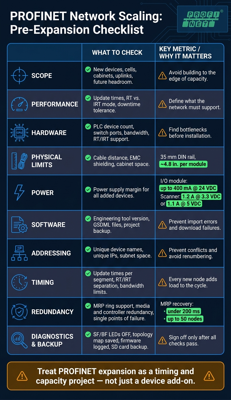
PROFINET Network Scaling Pre-Expansion Checklist
Hardware Readiness Checklist
Verify Controller, I/O Device, and Switch Capacity
Start with the manuals for every controller, I/O device, and managed switch already on the network. Check the supported device count, open ports, bandwidth, and RT/IRT support. Then compare that against your expansion plan, not just what’s installed today.
For controllers, make sure the unit can handle the number of I/O devices you plan to add and that it supports the real-time mode your application needs, whether RT or IRT. For managed switches, confirm they fit the planned topology and traffic load. Port count matters too, and this is where people get tripped up. A switch that works fine now can become a bottleneck the moment more devices come online.
You’ll also want to confirm that the hardware supports the redundancy mode you selected.
Confirm Topology Limits, Cabling, and EMC Compliance
Every topology comes with hard physical limits. Before you add segments, check the limits for the layout you plan to use, whether linear, daisy-chain, star, or ring.
For cabling, verify both the cable type and the distance limits your hardware allows. If distance or electrical noise pushes you beyond what copper can handle, fiber may be the better path. In that case, look for equipment with SFP support. Modules like the IC695PNS001 include SFP cages to support that move.
EMC compliance isn’t optional in industrial settings. Use proper shielding, grounding, and bonding. Keep signal cables away from power wiring. Use enclosures rated for the installation site. And if you’re using open-equipment components, install them in a suitable enclosure to meet safety and EMC rules.
Check Power Distribution and Cabinet Expansion Requirements
Every added device puts more demand on the power system. A standard 32-channel digital I/O module draws up to 400 mA at 24 VDC. A PROFINET scanner module installed in a PLC rack can draw 1.2 A at 3.3 VDC or 1.1 A at 5 VDC from the backplane. Add those numbers up and make sure the current power supplies still have enough margin.
Cabinet space can become a problem just as fast as power. High-density I/O modules often need 35 mm DIN-rail mounting and about 4.8 in. of horizontal rail space per module. If the panel is already crowded, plan for a new enclosure before the hardware shows up on-site.
A short check here can save a lot of pain later:
- Confirm new I/O modules include reverse-polarity protection.
- After sizing and installation, verify project files, device names, addressing, and timing settings.
sbb-itb-501186b
Software and Configuration Checklist
Verify Engineering Tools, Project Files, and GSDML Versions
Once you've confirmed hardware capacity, the next step is to lock down the software baseline.
Start by checking that your engineering tool version matches the controller platform you're using. If the versions don't line up, imports can fail, device parameters can behave oddly, and downloads may not work at all.
Every PROFINET device relies on a GSDML file. That file tells the controller how to talk to the device. Before you make any changes, verify that the GSDML file is current for every installed device and every new one you're adding. Then match each file against the device documentation and the project file so nothing slips through the cracks.
It also pays to keep a verified project backup before expansion starts. If something goes sideways, that backup can save a lot of time.
Confirm Device Naming, IP Addressing, and Available IP Capacity
Each device needs its own name and IP address. If two devices share either one, communication can stop and the fault can be a pain to track down.
Review your current address scheme and make sure it follows a consistent site standard. Also document subnet ranges and OT/IT boundaries before commissioning. This is one of those jobs that's easy to put off and annoying to fix later.
Plan the subnet structure now so you don't have to renumber devices down the road. Renumbering takes time and tends to create avoidable mistakes. If you're splitting the network across production areas, give each segment a clearly defined address range and document the segmentation boundaries before any new hardware is installed.
Validate Update Times, RT or IRT Settings, and Separate RT and IRT Traffic
Adding devices to a PROFINET network changes the timing math. Every new node uses bandwidth, and that can affect the update cycle for every other device on the same segment.
Before expansion, review the current update times in your project and confirm that the controller can still meet them after the extra load is added.
If your application uses IRT (Isochronous Real-Time) for motion control or other time-sensitive tasks, slow down and check things carefully. Keep IRT traffic separate from standard RT traffic by segment or interface. Then set and verify update times and bandwidth limits for each segment.
A simple checklist helps here:
- Review current update times
- Confirm controller timing under added load
- Separate RT and IRT traffic
- Set bandwidth limits by segment
- Document final update times and available bandwidth headroom
Use those timing and bandwidth numbers to confirm topology and redundancy choices next.
Topology, Redundancy, and Growth Planning Checklist
Confirm the Right Topology and Segmentation Strategy
Use the timing and bandwidth headroom from the prior checklist to judge whether the current topology can handle more devices. Map the new device count to the network you already have, then check for spare bandwidth and open ports.
It also helps to segment devices by cell or machine type. That keeps traffic isolated, makes control easier, and supports zone-based segmentation and access control.
Verify Media and System Redundancy Design
Match the redundancy model to the uptime target. That may mean media redundancy, controller redundancy, or both. Then confirm that every switch and field device in the design supports the approach you picked.
Next, verify recovery times and look for any single points of failure before you expand. A setup can look fine on paper and still have one weak link that causes trouble later.
After redundancy is in place, check that the network still has enough headroom for the next expansion phase.
Check Network Load and Reserve Capacity for Future Devices
Review current network load and set aside ports, addresses, and uplink capacity for future devices. Then verify switch port capacity, subnet address space, and cabinet or uplink expansion paths.
That way, future growth doesn't force a redesign.
Step-by-Step PROFINET Configuration Demo: GSD Files, Addressing Parameters, Manual vs Automatic...
Diagnostics, Maintenance, and Final Review Checklist
After topology and load checks, make sure diagnostics and recovery are in good shape before commissioning.
Verify Diagnostics, Alarms, and Monitoring Coverage
Before sign-off, check device health, link status, and alarm response. Look at all I/O modules and controllers and confirm the SF (System Failure) and BF (Bus Failure) LEDs are OFF on healthy devices. If either SF or BF is red, that points to an internal fault or a communication issue that needs to be fixed before commissioning.
| Diagnostic Feature | Healthy Status | What to Check |
|---|---|---|
| SF / BF LEDs | Both OFF | Verify the LEDs are off on healthy devices and test alarm response during a simulated bus failure. |
| RJ45 Link Indicator | Green ON or blinking | Solid green means link; blinking green means traffic. |
| PWR LED | Green ON | Verify the 24 VDC supply is within the required operating range, typically 15 to 30 VDC. |
| DI / DO Signal Status | Matches field state | Confirm the LED state matches the physical input or output signal. |
| Network Topology | Mapped and saved | Refresh topology after each wiring change. |
| Firmware Version | Logged in the project record | Log the version from the engineering tool or Micro-B port. |
A quick check here can save a lot of trouble later. For example, a blinking RJ45 light tells you traffic is moving, but that alone doesn't mean the whole station is healthy. You still need the LED states, topology map, and firmware record to line up.
Document Changes, Firmware Status, and Replacement Plans
Keep topology, firmware, and test records in one place. Save a current configuration backup on the controller's SD or SDHC card for onsite recovery. That way, if hardware gets swapped later, the expanded network can be restored without going through a full re-commission.
It also helps to log any wiring changes as they happen instead of trying to piece them together at the end. Small edits can snowball fast, and a clean record makes replacement work much less painful.
Conclusion: Final Pre-Expansion Sign-Off
Only sign off after diagnostics, documentation, firmware records, and backups are complete.
FAQs
When should I use RT vs. IRT?
Use PROFINET RT for standard industrial automation work where millisecond-level response times are enough. It runs on standard Ethernet hardware, so it fits most day-to-day communication needs without much fuss.
Use PROFINET IRT when timing has to be much tighter. It’s built for highly synchronized, deterministic performance with microsecond-level precision, which makes it a good fit for complex motion control and robotics. To keep jitter low, it needs specialized hardware.
How much spare capacity should I leave for growth?
Plan for 20% to 25% spare capacity above your first calculated design load. That extra headroom gives your PROFINET network space for future devices or heavier traffic without forcing big, system-wide changes.
For power support and distribution infrastructure, keep 25% to 30% spare positions and cap pathways at a 40% fill rate. Use measured demand data to set those numbers so you don’t oversize the system.
What should I back up before expansion?
Before you expand your PROFINET network, back up a complete, up-to-date record of the system. That simple step helps you avoid data loss and makes troubleshooting a lot less painful.
Make sure your backup includes:
- Existing devices, communication protocols, and related registers or objects
- A current one-line diagram and panel schedules
- Asset inventory, communication patterns, safety impact, and operational importance in a risk register
- Existing hardware settings, such as transformer vector groups





