




PROFINET Interoperability Testing Guide
If a PROFINET device has not been tested with your PLC, your firmware, and your network layout, I would not approve it for purchase or startup.
Here’s the short version: I would check five things first - stable cyclic I/O, correct device identity, usable diagnostics, clean recovery after cable or power loss, and written test records tied to exact hardware, firmware, and GSDML/GSDX files. A bench test that runs for 1–2 hours and includes 3–5 recovery cycles per device type can catch many of the problems that cause downtime, rework, and late FAT/SAT handoffs.
Before I move a device forward, I want proof that it can:
- exchange I/O data without random dropouts
- show the right vendor ID, device ID, name, MAC, and file match
- send alarms my PLC and maintenance team can read
- reconnect after a fault without manual renaming or IP work
- produce logs, screenshots, and version records I can review later
I would also keep the test bench close to the plant setup:
- same controller and engineering tool
- same switch type, topology, and cable class
- same module layout and device naming plan
- same ring setup if MRP will be used in the field
Then I would verify the basics before any live I/O test:
- GSDML matches the exact device and firmware
- DAP and modules match the installed hardware
- device names and IP settings are correct
- fault alarms appear with labels the controller can use
After that, I would run startup and fault tests in the mixed-vendor setup, including:
- name mismatch
- module mismatch
- cable disconnect
- power loss
For each one, I would log detection time, failure time, and recovery time. If a seller claims compatibility, I would ask for the same records before payment: conformance report, interoperability test report, topology drawing, version list, controller project notes, and fault/recovery evidence.
Bottom line: this guide is about replacing vendor claims with test proof you can review, compare, and sign off on with less risk.
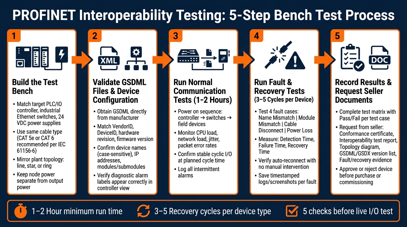
PROFINET Interoperability Testing: 5-Step Bench Test Process
PROFINET Network Troubleshooting Made Easy: PROFINET TEST TOOL, An introduction
How to Build a PROFINET Test Bench
Build the bench so it looks like the plant you plan to run. That way, the test checks actual compatibility, not behavior that only shows up on a lab setup. The bench doesn't have to be big. It just has to match the planned deployment closely. If you swap in office Ethernet switches, use different cable types, or test with a controller that's not going into the plant, the results can fall apart later.
Match the Test Bench to the Planned Deployment
Start with the hardware you plan to use in the field: the target PLC or IO controller, the IO devices you're set to buy, industrial Ethernet switches, 24 VDC power supplies, and the same cable type and connector style called for in the installation. Use the same engineering tool as the plant system too, so GSDML handling and diagnostics line up with what you'll see during commissioning.
For cabling, PROFINET guidance sets CAT 5 as the minimum under IEC 61156-6, but CAT 5e or CAT 6 is recommended for new installations.
Before you power any outputs, keep node power separate from output power. That lets you check communication and device naming first, without the risk of moving an actuator by accident. After power is on, inspect connectors for damage, confirm shield continuity to panel ground, and keep PROFINET cables away from high-voltage and VFD output cables. If the runs have to cross, do it at 90°.
Then check port status LEDs on every switch and device: link, speed, and activity. If you see flapping links or error indicators, fix those before you move on to logical tests. Physical-layer issues can look like PROFINET setup failures, which is why it's smart to clear them first.
Once the hardware matches the plan, check the network layout before you start logical testing.
Review Network Topology Before Testing Starts
Wire the bench exactly like the deployed network will run, whether that's line, star, or ring, and verify that the physical connections match the plan. It helps to sketch the bench layout with device order, switch locations, uplinks, and topology type. Label each cable with its own ID, such as L1-01 for Line 1, Device 1, and record the matching device name, IP address, and subnet mask for every node.
A line topology is easy to wire, but there's a catch: one break can cut off everything downstream. If the planned deployment uses Media Redundancy Protocol (MRP), close the line as a ring on the bench and test it that way too. Every node in the ring must support MRP, and one node has to serve as the redundancy manager.
Use a network scan tool to compare the live bench with the topology drawing.
After the topology lines up with the deployment, validate the GSDML file and device settings against the exact hardware.
How to Validate GSDML Files and Device Configuration
Once the topology lines up with the deployment, validate the GSDML and device settings before you run any cyclic I/O test. Start with the file and the device identity. Then move to live communication.
A GSDML file is the device definition for a PROFINET device. If it doesn't match the hardware and firmware, the project may look fine in the engineering tool and still fail when you're on site. That's why GSDML validation is an engineering task, not just box-checking.
Match the GSDML File to the Exact Device and Firmware Version
Get the GSDML straight from the device manufacturer. It needs to match the exact device and firmware revision you're using. One GSDML may support several variants through DAPs, so you need to pick the DAP that matches the hardware. If you don't, the connection will fail.
Import the file through the engineering tool's GSD install or catalog update process. After that, verify that the VendorID, DeviceID, hardware revision, and firmware version in the GSDML's DeviceIdentity block match what the physical device reports.
If you're buying through a marketplace or reseller such as Electrical Trader, ask for the vendor-backed GSDML or signed GSDX for the exact device revision.
Ask for the signed GSDX package too. Its digital signature confirms that the file is authentic and hasn't been changed.
Confirm Device Names, IP Settings, Modules, and Alarms
After the GSDML is imported and matched, run through four checks before starting cyclic testing.
| Check | What to Verify |
|---|---|
| PROFINET device name | Unique for each device; matches the controller project exactly, including case sensitivity |
| IP address and subnet mask | No duplicates; matches the engineering tool and network design |
| Modules and submodules | Each installed module's order number and type match the GSDML catalog entry; all show OK status after startup |
| Diagnostic alarms | Expected alarm classes are declared in the GSDML; test by triggering a fault and confirming the alarm appears with the correct label in the controller view |
After the download, check the hardware diagnostics for module mismatch, device-name mismatch, or IP conflict messages. Alarm code 0x8001 also points to a configuration mismatch, often caused by incorrect modules or parameters. If you see unknown alarms, the GSDML likely doesn't include the diagnostic definitions needed to troubleshoot the issue.
If these checks pass, move to controller-to-device interoperability testing in the mixed-vendor setup.
sbb-itb-501186b
How to Run Controller-to-Device Interoperability Tests in a Mixed-Vendor Setup
With GSDML and device settings checked, the next step is simple: test how the controller and devices behave on the live mixed-vendor network. Static checks only get you so far. At some point, you need to see what happens when everything is powered up and talking for real.
Test Normal Communication and Startup Behavior
Start with the normal startup sequence: power on the controller, then the switches, then the field devices. Watch for each device to enter data exchange cleanly, with no name-mismatch or reachability alarms.
You also want to confirm that data exchange starts inside the expected commissioning window. A device that eventually connects but takes too long can still cause headaches later. Check that each device reaches data exchange and stays there at the planned cycle time.
Let the system run for at least 1–2 hours while you monitor:
- Controller diagnostics
- Device diagnostic buffers
- Switch statistics
During that run, log CPU load, network load, jitter, and packet error rates. The goal is steady data exchange, steady diagnostics, and steady cycle time across devices from different vendors. If intermittent alarms pop up now and then, don't brush them off. Those sporadic diagnostics are a warning sign and should be checked before deployment.
Test Fault Handling and Device Recovery
After normal operation looks good, move on to fault testing. This is where mixed-vendor setups often show their rough edges. Introduce faults on purpose and verify how the system reacts.
Test these four fault cases: name mismatch, module mismatch, cable disconnect, and power loss.
For the name mismatch test, assign a name in the controller project that does not match the physical device. The controller should refuse to start data exchange and should report a clear name mismatch diagnostic. Just as important, this fault should not disturb other devices on the network.
For a module mismatch, set a different module type in the engineering tool than the one actually installed. The controller should report a configuration mismatch on the affected slot while leaving all other correctly set devices in operation.
For cable disconnect and power loss, measure three things:
- Detection time
- Failure time
- Recovery time
The controller should detect the loss within the configured watchdog time and report a station-failure alarm. When the cable is reconnected or power returns, the device should go back to data exchange on its own. No manual babysitting.
Run 3–5 recovery cycles per device type and note any vendor-to-vendor differences. Recovery time can vary based on device boot time and vendor design, so this part matters more than it may seem at first glance.
Save timestamped logs or screenshots for each fault, along with the device and firmware version.
Record Mixed-Vendor Results in a Test Matrix
Write down every test case in a matrix. That gives buyers and commissioning teams a clear, auditable record of what was tested and what actually happened.
| Test ID | Date Tested | Responsible Engineer | Controller (Model/FW) | Device (Model/FW) | Topology | Cycle Time | Test Condition | Expected Result | Actual Result | Logged Metrics | Pass/Fail | Notes |
|---|---|---|---|---|---|---|---|---|---|---|---|---|
| TC-01 | 03/15/2026 | A. Rivera | Controller A / FW x.x | Device B / FW x.x | Line topology | 8 ms | Normal startup | Data exchange within 30 sec | Data exchange in 12 sec | No alarms, stable I/O | Pass | - |
| TC-02 | 03/15/2026 | A. Rivera | Controller A / FW x.x | Device B / FW x.x | Line topology | 8 ms | Name mismatch | Controller blocks data exchange and reports a mismatch | Mismatch diagnostic raised, other devices unaffected | Screenshot captured | Pass | - |
| TC-03 | 03/15/2026 | A. Rivera | Controller A / FW x.x | Device C / FW x.x | Ring topology | 8 ms | Cable unplug/replug | Station-failure alarm reported; auto-reconnect | Reconnected in 7 sec, no residual diagnostics | Recovery time logged | Pass | - |
| TC-04 | 03/15/2026 | A. Rivera | Controller A / FW x.x | Device C / FW x.x | Ring topology | 8 ms | Power loss/restore | Auto-reconnect, no manual steps needed | Reconnected in 14 sec after 3 cycles | Recovery time logged | Pass | Boot time longer than TC-03 |
| TC-05 | 03/15/2026 | A. Rivera | Controller A / FW x.x | Device D / FW x.x | Line topology | 4 ms | Module mismatch | Configuration mismatch on affected slot | Alarm raised; other slots operational | Diagnostic log exported | Pass | - |
If you see repeated failures, flag them before purchase approval or commissioning. The same matrix can also help when you ask the seller for matching test records, which makes side-by-side review much easier.
What Test Records to Request From the Seller and a Final Deployment Checklist
Documents That Support Interoperability Claims
Use your test matrix to check the seller's claims one document at a time. The goal is simple: match each seller record to the same test cases in your matrix, so you're not relying on broad promises or sales language.
At a minimum, ask for the items below:
| Document | What to Look For |
|---|---|
| PROFINET conformance certificate or conformance report | PNIO version, conformance class, network load class, and optional features such as MRP |
| Interoperability test report with startup, fault, and recovery results | Matching your controller, device, and firmware versions |
| Network topology diagram | Controllers, switches, devices, line/ring structure, and any VLAN segmentation |
| Exact device, firmware, and GSDML/GSDX version list | Model numbers, hardware revisions, roles, MAC addresses, PROFINET device names, firmware versions, and IP assignments |
| Controller project notes or export | Configured device names, IP settings, IO modules, alarm settings, and diagnostics settings |
| Fault/recovery evidence | Detection times, reconnection times, and diagnostic messages |
| Network performance summary | Seller's measured network load, jitter, and error frame counts confirming performance targets were met |
If you're sourcing PROFINET-capable electrical equipment through Electrical Trader, ask for these records before payment or deployment. That timing matters. It's much easier to spot a mismatch on paper than after a device is already on the floor.
For used or refurbished devices, ask for:
- Nameplate photos
- A controller project screenshot showing successful I/O exchange
Use these records to approve or reject the device before commissioning.
Conclusion: Minimum Checks to Complete Before Purchase or Commissioning
Before purchase or commissioning, confirm that the seller can document conformance, mixed-vendor interoperability, the tested topology and device list, the exact GSDML/GSDX version, and alarm, fault, and recovery results.
FAQs
What failures can bench testing catch early?
Bench testing helps you catch communication and hardware problems before a device ever reaches the field. That matters, because it’s much easier to fix issues on a workbench than during startup or after installation.
It can surface internal faults, communication errors, and setup mismatches like the wrong default baud rate, reversed byte order, or non-standard function codes.
Bench testing also confirms that 24 VDC power stays within the 15 to 30 VDC range. At the same time, it checks that SF and BF LEDs remain off during normal operation, and that LED status lines up with the actual physical I/O states.
How close should the test bench be to the real plant setup?
The lab bench should look as much like the actual field setup as possible. That means connecting IEDs, gateways, HMIs, and network gear in a way that matches the planned site layout. When you do that, you’re far more likely to spot integration problems, interference, or communication issues before anything reaches the field.
Field checks still matter. But they should back up formal test reports, not stand in for them. Those reports need to cover lab conditions like grounding, load, and cable routing so the team has a clear record of how the system performed under test.
Which records should I request before approving a device?
Before approving a PROFINET device, ask for the full commissioning and test record that shows it actually communicated and was checked in context.
That record should include:
- the vendor’s full test report, with the test method number, test duration, pass criteria, and pass/fail results
- firmware and software versions, plus documentation for the exact model and revision
- proof that the GSDML revision is correct and matches the project documentation
- signed test sheets, including any retests, deviations, closure records, and as-built settings/files





