
Preventing Material Fatigue in Integration
Material fatigue is a silent process that can lead to sudden failures in electrical systems, often caused by repeated thermal cycling, mechanical vibrations, and environmental stressors. These forces create cracks that grow over time, compromising the durability of components. Here’s what you need to know:
-
What causes fatigue?
- Thermal stress from temperature fluctuations.
- Vibrations from machinery and loose connections.
- Corrosion, moisture, and chemical exposure.
-
How to prevent it?
- Use materials with high fatigue strength and proper heat treatments.
- Design systems to minimize stress concentrations.
- Conduct regular maintenance and inspections to catch early signs of damage.
- Train teams to recognize and address potential fatigue risks.
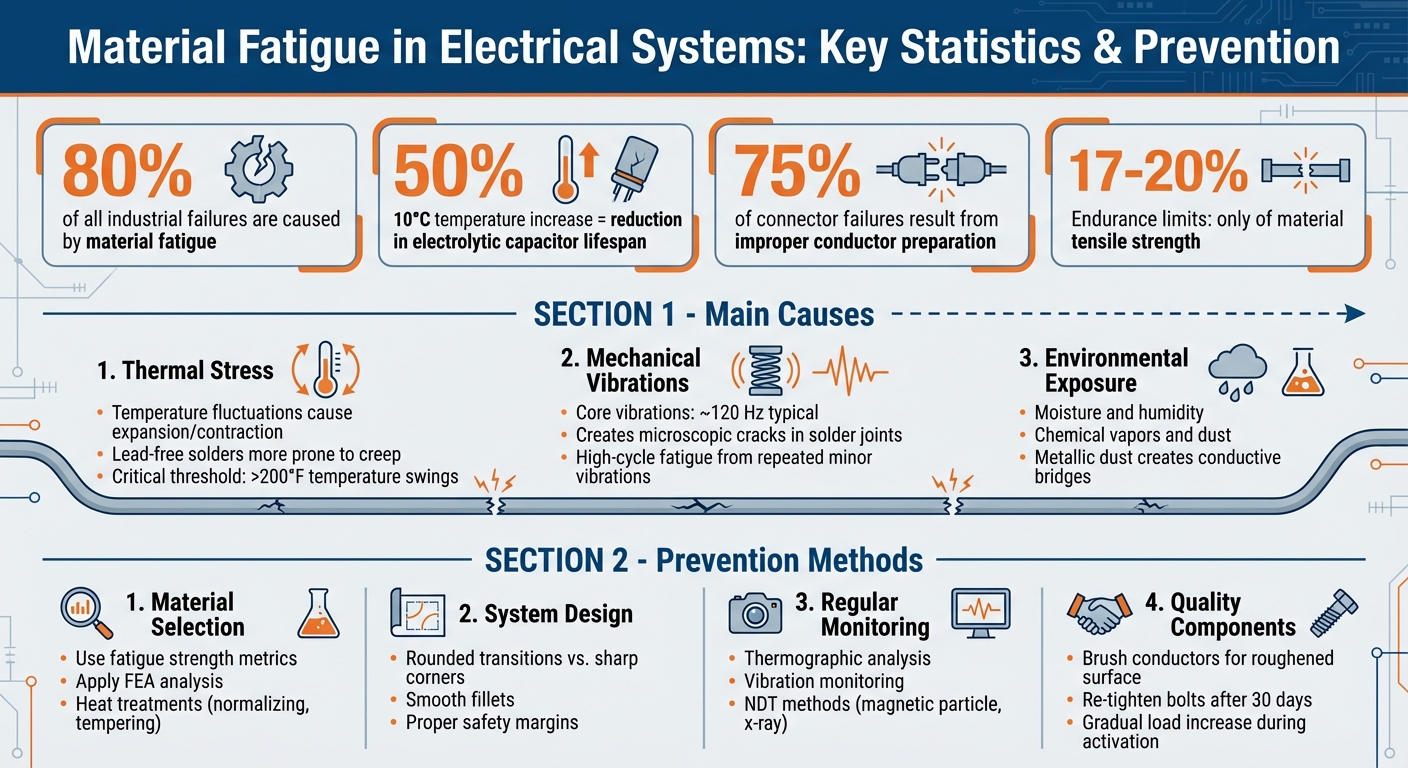
Material Fatigue Statistics and Prevention in Electrical Systems
Main Causes of Material Fatigue in Electrical Systems
Thermal Stress and Temperature Fluctuations
Electrical components endure significant strain from repeated thermal cycles. These cycles cause materials to expand and contract, placing stress on connection points, solder joints, and interfaces. Over time, this stress accumulates, leading to material fatigue.
For example, a 10°C increase in operating temperature can cut the lifespan of electrolytic capacitors in half. Thermal stress also impacts solder joints, causing creep and plastic deformation that result in permanent structural changes. Eventually, these changes lead to fractures. Research shows that thermomechanically driven stress accounts for a large percentage of electronic failures.
Modern lead-free solders, while environmentally friendly, behave differently under thermal stress compared to traditional tin-lead alloys. These newer materials exhibit unique microstructural responses, making them more prone to creep and thermomechanical fatigue. Without adequate thermal management during assembly, equipment with lead-free solder may fail prematurely.
Additionally, mechanical forces from regular operations often exacerbate these thermal stresses, further accelerating material fatigue.
Mechanical Loads and Vibrations
Vibrations from motors, generators, and nearby machinery create mechanical stress that can damage electrical components over time. These vibrations often cause microscopic cracks in solder joints and fretting at connectors. As these small defects grow, they lead to intermittent faults and, eventually, complete failures. Even minor vibrations, when repeated over a long period, can result in high-cycle fatigue.
Installation practices play a critical role here. For instance, electrical cabinets mounted directly on vibrating machinery experience much higher stress compared to those isolated with dampers. Loose connections can amplify vibration effects, while equipment near heavy machinery is constantly exposed to mechanical loading that speeds up material wear and cracking.
While thermal and mechanical factors are major contributors, environmental conditions also play a significant role in material degradation.
Environmental and Chemical Exposure
Environmental factors often accelerate material fatigue in ways that thermal or mechanical stress alone cannot. Moisture and humidity, for example, can lead to electrical leakage, corrode circuit traces, and degrade insulation. Moisture commonly enters through unsealed cable glands or cabinet doors during temperature fluctuations. Meanwhile, chemical vapors and dust can damage coatings, plastics, and solder joints.
In machining environments, metallic dust poses a unique risk. It can settle on printed circuit boards, creating conductive bridges that lead to short circuits. Organic fibers from textile or paper dust can also block airflow, clog cooling fans, and trap heat on components, worsening thermal fatigue.
"Most industrial electronics don't fail because they're badly designed - they fail because the environment they operate in slowly pushes them outside their intended limits." - Delta Automation Inc.
Corrosion caused by environmental factors weakens connections, making them more vulnerable to thermal and mechanical stresses. Dust that traps moisture against surfaces not only accelerates corrosion but also interferes with heat dissipation, significantly reducing component life. Together, these environmental and operational stresses create a perfect storm for material fatigue in electrical systems.
sbb-itb-501186b
How to Prevent Material Fatigue in Electrical Integration
Choosing the Right Materials
The first step in preventing material fatigue is selecting materials that can handle the stresses they'll face during operation. A key measure here is fatigue strength, which tells you how many cycles a material can endure at a specific stress level. This is far more practical than relying on theoretical fatigue limits. To pinpoint areas where cracks might form, engineers can use Finite Element Analysis (FEA), which highlights complex stress points.
"Once we have a data set and we know what the material is capable of, we can start putting in the design or the part-specific requirements."
– Jason Bergman, Metallurgist, Eagle Alloy
For materials like carbon steel alloys, heat treatments such as normalizing and tempering are effective in reducing residual stresses, which are often the culprits behind crack propagation. Tools like S-N curves (stress versus number of cycles) are invaluable for predicting fatigue life under specific loads. These insights guide the choice of alloys and treatments for demanding projects, ultimately improving the durability of electrical systems. For sourcing quality electrical components, platforms like Electrical Trader provide equipment designed to meet rigorous performance demands.
However, material selection alone isn’t enough - how the system is designed plays a significant role in managing stress.
Improved System Design
Once you've chosen the right materials, it's essential to design the system in a way that minimizes stress concentrations. Sharp corners and sudden transitions in geometry are notorious for creating stress hotspots, which can accelerate crack formation. Replacing these with rounded transitions and smooth fillets helps distribute stress more evenly, reducing the risk of failure.
Design considerations should also include proper safety margins and ensuring that all components are compatible to extend the system's lifespan. Non-destructive testing (NDT) methods like magnetic particle testing or x-ray testing are excellent for spotting microscopic cracks in critical components before they grow. Working closely with manufacturers throughout the design and production process ensures that the chosen materials are cast and processed under strict quality standards.
Regular Maintenance and Monitoring
Even with the best materials and design, consistent monitoring is crucial to catching potential problems early. Routine inspections can help identify signs of fatigue damage before they become severe. Pay particular attention to high-stress areas such as weld toes, drilled holes, and threaded sections - these are common starting points for cracks. What might look like surface rust or slightly loose fasteners could actually be early indicators of fatigue damage.
"Fatigue damage is frequently mistaken for cosmetic wear. Surface rust around a weld may appear superficial... These early signs deserve closer evaluation."
– Manufacturing Engineerings
Advanced techniques like thermographic analysis and vibration monitoring can detect subtle signs of fatigue, allowing for timely repairs. If operational conditions change - like altered production loads or equipment modifications - it's crucial to reassess for new stress concentrations or load paths. Tracking factors such as startup-shutdown cycles and thermal fluctuations is also important, as these contribute to low-cycle fatigue and localized deformation.
Best Practices for Reliable Integration
Following Manufacturer Guidelines
Getting the installation process right is essential to avoid material fatigue. One key step is ensuring that incoming and outgoing cables are well-supported to prevent mechanical stress on transformer bushings or connections, which can cause cracks and even failures over time.
Post-installation checks are equally important. For instance, re-tightening cable retaining bolts after 30 days helps maintain secure connections and prevents issues like moisture infiltration. When activating equipment, gradually increase the load while monitoring voltages and currents to confirm stability. Placement also matters - consider core vibrations, typically around 120 Hz, as these can contribute to wear and tear over time.
"The successful operation of a transformer is dependent on proper installation as well as on good design and manufacture."
– Edvard Csanyi, Founder, Electrical Engineering Portal
By adhering to these guidelines, you set the stage for reliable performance and maximize the potential of high-quality components.
Using High-Quality Components
The components you choose play a huge role in resisting fatigue. For example, nearly 75% of connector failures stem from improper conductor preparation. This highlights the importance of not only sourcing durable parts but also handling them correctly. A simple yet effective practice is brushing conductors with a stainless steel or brass brush to create a roughened surface, which enhances electrical contact - even on brand-new, shiny conductors.
"The primary purpose of brushing the conductor is to provide a ROUGHENED SURFACE which will ultimately make a better electrical contact than the shiny surface."
– CIGRE Working Group B2.50
Be mindful of the tools you use. Avoid ferrous steel brushes on aluminum conductors, as they can leave rust residue, and skip steel wool, which might deposit fibers that lead to corona issues. Additionally, maintain strict inventory checks during assembly to prevent foreign objects from being left inside equipment, reducing the risk of internal damage. For sourcing reliable electrical components that meet high-performance demands, platforms like Electrical Trader offer a range of options tailored to tough applications.
But even with top-notch components, the expertise of your team is critical to reducing fatigue risks.
Training and Workforce Education
Proper installation and quality parts are only part of the equation. A well-trained team is just as essential for spotting early signs of fatigue, such as microcracks or subtle wear. Workers must understand that fatigue often develops at stress levels lower than a material’s ultimate tensile strength, meaning cyclic loads demand close monitoring - not just maximum load limits.
Routine inspections are key. Focus on areas where stress tends to concentrate, like around hole placements or bend radii, as these spots are more prone to failure. Linemen should practice compression techniques on spare conductors at ground level to ensure consistency before working at heights. Teams also need to recognize when equipment is behaving abnormally, which could indicate vibration-induced fatigue. Additionally, they should be able to distinguish between different types of fatigue, such as thermal fatigue caused by temperature swings or corrosion fatigue from environmental exposure.
Improving Fatigue Resistance
Conclusion
Material fatigue is responsible for nearly 80% of all industrial failures, making its prevention a top priority in electrical integration. The process of damage is often slow and hidden, only becoming apparent when a major failure occurs. This is why taking proactive steps is far more effective than relying on reactive repairs.
Fatigue isn’t just about the materials themselves - it’s a challenge that spans design, manufacturing, inspection, and ongoing maintenance. For instance, crack growth under repeated stress often goes unnoticed until it leads to failure. In many steels and alloys, endurance limits are typically only 17–20% of their tensile strength.
"Fatigue is not just a materials topic. It is a design, verification, fabrication, inspection, and life-management problem."
– Yurii Shumak, Structural Engineer, SDC Verifier
Preventing fatigue requires a combination of strategies. These include optimizing geometry with smooth transitions and larger radii, ensuring top-notch welding quality, using surface treatments like shot peening, and conducting thorough non-destructive testing to catch cracks early [7, 13]. Additionally, managing thermal fatigue is crucial, especially when temperature fluctuations exceed 200°F during operating and shutdown cycles. Controlling heating and cooling rates can significantly reduce this risk.
Think of fatigue prevention as a comprehensive life-management strategy, not just a matter of choosing the right materials. By addressing stress points, enforcing strict quality controls, and maintaining consistent monitoring, you can protect your equipment and ensure operational safety. For more insights on reliable integration and high-quality electrical components, check out Electrical Trader.
FAQs
What are the earliest signs of fatigue in electrical connections?
Flickering or dimming lights can be an early warning sign of trouble in electrical connections. These subtle changes often point to loosening or wear in the contacts. If left unchecked, these small issues can escalate, leading to more serious problems down the line.
How do I decide whether heat, vibration, or the environment is the main cause?
To pinpoint the main cause of material fatigue, focus on failure patterns and the conditions under which they occur:
- Heat: If the failures correspond to temperature changes or thermal cycling, heat could be the culprit.
- Vibration: Cracking that appears after repeated mechanical stresses suggests vibration as a possible cause.
- Environmental factors: The presence of moisture or corrosion could indicate these as contributing factors.
Carefully review the operational history and the context of the failure to identify the primary factor behind the fatigue.
What monitoring tools give the fastest warning before a failure happens?
High-speed power quality analyzers and condition monitoring tools excel at quickly spotting failures. These devices detect transient electrical events and subtle warning signs, offering early alerts that can help avoid costly equipment downtime.


