




10 Pre-Commissioning Tests for Substation Control
More than half of protection misoperations in one 2021 Western Interconnection review were tied to CT/PT wiring and connection issues. That’s the big reason I’d never treat pre-commissioning as box-checking.
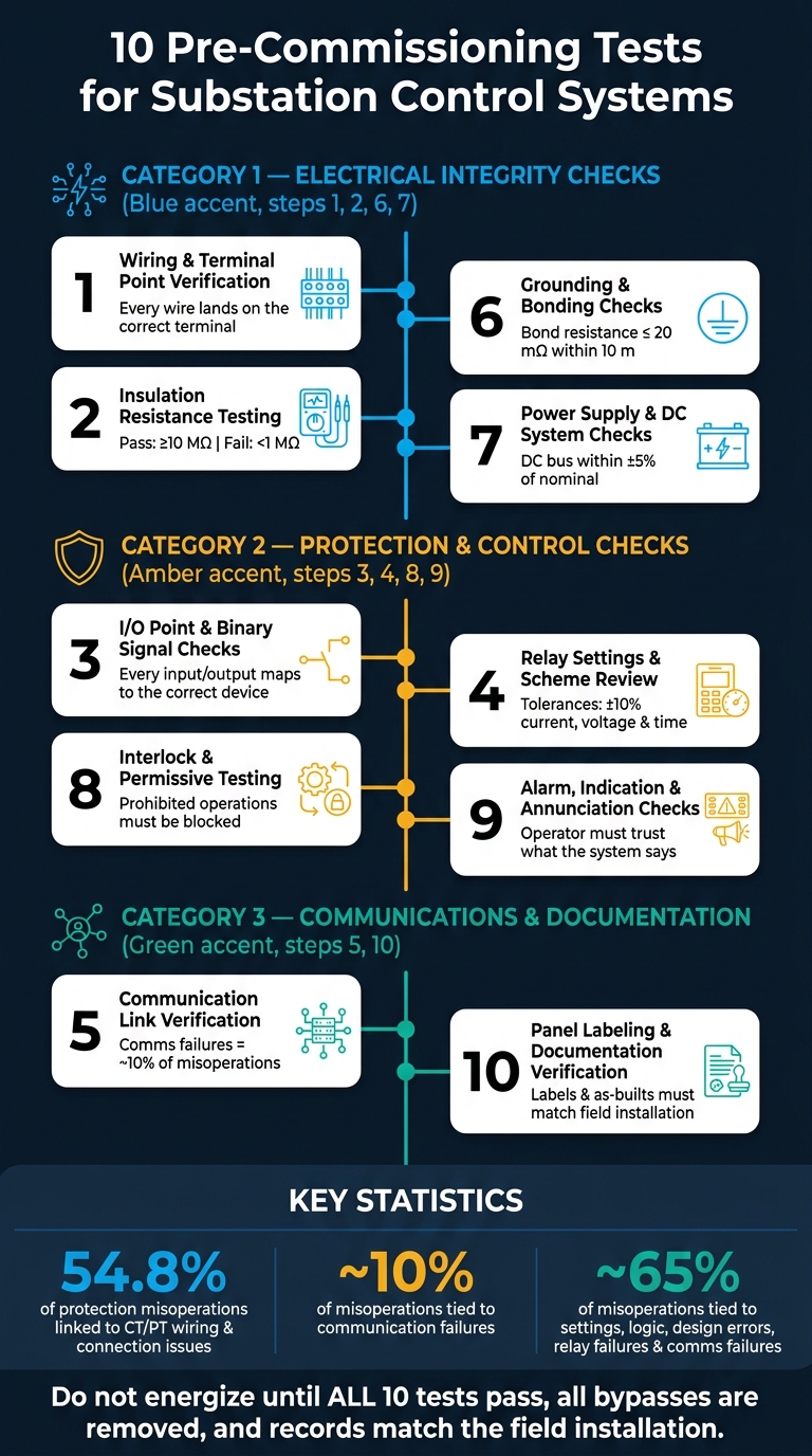
If I had to sum up this article in one line, it would be this: before any primary equipment is energized, I need to prove the secondary system is wired right, insulated right, set right, powered right, and reporting the right status to operators. The 10 tests in this article do that in a clear order, from basic electrical checks to logic, alarms, communications, and final records.
Here’s the full checklist covered in the article:
- Wiring and terminal point verification
- Insulation resistance testing
- I/O point and binary signal checks
- Relay settings and scheme review
- Communication link verification
- Grounding and bonding checks
- Power supply and DC system checks
- Interlock and permissive testing
- Alarm, indication, and annunciation checks
- Panel labeling and documentation verification
A few numbers stand out:
- 54.8% of protection misoperations in the cited Western report were linked to CT/PT wiring and connection issues
- About 10% were tied to communication failures
- About 5% involved the DC system in the cited NERC-based paper
- The article also notes that about 65% of misoperations are tied to settings, logic or design errors, relay failures, and communication failures
So the main point is simple: I should check the secondary system in layers. First the physical circuits. Then insulation, grounding, and DC supply. Then point mapping, relay logic, interlocks, alarms, and network paths. Last, I make sure labels, drawings, and test records match what is in the panel.
10 Pre-Commissioning Tests for Substation Control Systems
Electrical Substations 101 Hands On with Equipment & Testing Procedures
sbb-itb-501186b
Quick Comparison
| Test | What I’m proving before energization | Main risk if missed |
|---|---|---|
| Wiring verification | Each wire lands on the correct terminal | Wrong trips, bad indications, crossed circuits |
| Insulation resistance | No weak insulation to ground or between conductors | False pickup, shorts, unsafe conditions |
| I/O checks | Each input and output maps to the correct point/device | Wrong SCADA status, wrong command target |
| Relay settings review | Relay values and logic match approved files | Missed faults or unwanted trips |
| Communication links | Data, commands, and time sync move to the right place | Stale data, lost status, failed control path |
| Grounding and bonding | Metal parts and shields are bonded as designed | Noise, bad measurements, shock risk |
| DC system checks | Battery, charger, and DC feeders support control/protection | Loss of trip/control power |
| Interlocks and permissives | Unsafe switching actions stay blocked | Equipment damage, unsafe switching |
| Alarm checks | Faults show up with the right text, horn, and timestamps | Operator confusion, missed alarms |
| Labeling and documentation | Field labels and records match the installed system | Wrong switching, bad maintenance records |
If you want the short version, it’s this: I would not energize a bay until all 10 checks pass, all test bypasses are removed, and the final records match the field installation.
What Pre-Commissioning Covers in Substation Control
Pre-commissioning happens after installation and before energization. Its job is simple: make sure the secondary systems are installed, wired, and set up the right way before any primary equipment goes live.
It’s not about testing how the substation performs while energized. It’s about checking the setup before that point, when fixes are still far less painful.
In practice, this work covers six main areas: control and marshalling panels, relay interfaces and protection schemes, station communications network, AC and DC auxiliary power, alarm annunciation and supervision, and interlocks and permissives. Together, these checks make sure signaling is correct, logic works as intended, and operators can see what they need to see before the first breaker is closed.
That matters more than it might seem at first glance. A 2021 Western interconnection report linked 54.8% of protection system misoperations to CT/PT wiring and connection issues. Pre-commissioning is the first real chance to catch problems like that before the substation is energized.
Next comes wiring and terminal point verification.
1. Wiring and Terminal Point Verification
Wiring and terminal point verification is the first hands-on check after the drawing review and physical inspection. Before you apply any voltage, every conductor needs to land on the right terminal, match the approved wiring diagrams, and be fastened with the right ferrules, lugs, and torque values. The aim is simple: make sure each circuit is terminated exactly the way it was designed.
What the Test Checks
This check covers point-to-point verification of control, protection, and indication circuits against the approved connection diagrams and control schematics. That includes CT and PT secondary circuits, DC control and alarm wiring, breaker trip and close circuits, interposing relays, hardwired interlocks, and control power wiring.
Technicians also compare wire ferrules, color coding, terminal numbers, panel labels, and cable schedules against the drawings. Spare or unused cores should be identified and isolated so they don't cause trouble later.
How It's Performed
Teams usually begin with a document review and a visual inspection of panel wiring, terminal blocks, and cable schedules before any electrical testing starts. They confirm the drawing revision matches the physical panel, then work through each circuit step by step.
A common approach is to start at one end of a wire, check that the ferrule and terminal match the schematic, and then trace the wire to the other end. A continuity tester, digital multimeter, or loop-check method is then used to confirm the connection. Many utilities mark each verified wire on the schematic so there's a clear record of what has already been checked.
Pass/Fail Indicators
Pass: Every wire lands on the right terminal, conductor IDs match the drawings, terminations are tight, and there are no unintended shorts, opens, or cross-connections.
Fail: Mismatched terminal numbers, reversed polarity, loose or damaged terminations, missing wire markers, wrong cable cores, or any control circuit that doesn't match the approved schematic. If any termination is wrong, it must be corrected and tested again.
Pre-Energization Confirmation
CT circuits must stay continuous, with shorting links or blocks set correctly. Temporary test leads, jumpers, and commissioning changes should be removed before sign-off. If a circuit was corrected, test it again.
For high-consequence points like trip wiring and DC supply polarity, a two-person verification method is a practical way to cut down human error and catch mistakes before startup.
Once wiring passes, move to insulation resistance testing.
2. Insulation Resistance Testing
After wiring verification, insulation resistance (IR) testing checks conductor insulation before energization. Put simply, it helps make sure the insulation between conductors and ground - and between conductors when required - is strong enough to prevent false operation and unsafe touch voltage.
What the Test Checks
IR testing applies to DC control and trip circuits, CT and VT secondary wiring, interpanel wiring, and discrete I/O cables connected to IEDs, RTUs, PLCs, and bay controllers. Each circuit is tested conductor-to-ground. The aim is simple: confirm leakage current stays low enough that equipment doesn't operate by mistake.
How It's Verified
For low-voltage control and secondary circuits, apply 500 V DC for 60 seconds. Before that, isolate relays, IEDs, RTUs, and PLC cards, short CT secondaries, and confirm lockout/tagout is in place.
Pass/Fail Indicators
| Reading | Interpretation |
|---|---|
| ≥ 100 MΩ | Excellent - expected on new installations |
| 10–100 MΩ | Good - acceptable, no action needed |
| 1–10 MΩ | Marginal - investigate before energizing |
| < 1 MΩ | Fail - circuit must be repaired and retested |
The number at the end of the test isn't the whole story. If the reading keeps falling during the 60-second window, that's a warning sign even when the final value is above the minimum. Stable or rising resistance points to healthy insulation polarization.
Any failed circuit must be logged as a defect, repaired or dried out, and then tested again before clearance.
Pre-Energization Confirmation
Record the circuit ID, cable tag, test voltage, ambient temperature, resistance value, and pass/fail status on signed and dated test sheets. No bay or panel should be energized until every circuit on the IR test list has a passing result and all corrective actions are formally closed.
After wires are reconnected to relays and IEDs, run a quick point-to-point continuity check. It's a simple last look that helps catch any mis-termination introduced during isolation.
Next: I/O point and binary signal checks.
3. I/O Point and Binary Signal Checks
Once wiring and insulation checks are done, the next step is to make sure every binary point works end-to-end. Those earlier checks show the circuit is there. This test shows the circuit does what it’s supposed to do before energization.
What the Test Checks
Check every binary input to make sure it lands on the right relay or RTU point and the right SCADA tag. That includes breaker 52a/52b contacts, disconnect positions, protection alarms, and pressure switches.
Then check every binary output to confirm it operates only the intended device. That covers trip, close, interlock, permissive, and alarm signals.
For IEC 61850 systems, confirm GOOSE publication and subscription work as approved. For Modbus, DNP3, and IEC 61850 databases, confirm each address and logical point matches the approved configuration.
How It's Verified
Binary input checks are pretty direct. Apply rated DC voltage, such as 125 VDC, to each input terminal and confirm the relay or IED display shows the right state change.
For binary outputs, use relay software to force each output for a short time. Then verify contact operation at the output terminals with a multimeter. After that, trace the signal through panel and field terminations to make sure it reaches the intended device.
After the field check, review that same point in the relay, HMI, and SCADA database. Operate the field device or test switch, then confirm the correct HMI and SCADA point changes state and records the event the right way.
For command outputs like breaker open and close, isolate the trip and close coils first. Then verify the right output relay actuates and the right SCADA command reaches the intended output under a permit-to-work, with the bay de-energized.
Pass/Fail Indicators
| Condition | Result |
|---|---|
| Correct state change at relay, HMI, and SCADA with proper label | Pass |
| Only the intended breaker or device responds to a command | Pass |
| The intended point does not change, or the wrong point/device changes | Fail |
| Duplicate, missing, or incorrectly labeled alarms | Fail |
| Invalid or stale GOOSE status | Fail |
If anything fails, log it in the commissioning punch list with the point ID, defect description, suspected cause such as wrong terminal, inverted logic, or incorrect address, corrective action, and re-test date. The point stays open until the re-test passes.
Pre-Energization Confirmation
Before the bay is cleared for energization, every planned I/O point needs a passing result in the commissioning records. Also confirm time synchronization is active so event logs have accurate timestamps.
It helps to cross-check I/O results against wiring verification records and relay settings. If one record says a point is right but another says something else, that’s a red flag. Last step: remove all test mappings, forced outputs, and overrides before sign-off.
Next, verify relay settings and scheme review.
4. Relay Settings and Scheme Review
Once the binary points are proven, the next step is to check the protection logic behind them. And once the I/O points are confirmed, you need to verify relay settings, scheme logic, and CT/VT ratios against the approved documents before energization.
What the Test Checks
At its core, this review compares each relay's programmed settings with the approved settings sheets and the protection coordination study. That includes checking pickup values, time delays, time-current curves, distance zones, CT/VT ratios, and which protection functions are turned on, such as overcurrent, differential, distance, breaker failure, and auto-reclose.
It doesn't stop at the relay itself. The review also checks scheme logic, including breaker failure initiation, auto-reclose sequences, interlocks, and permissives. In IEC 61850 systems, GOOSE and sampled value mappings also need to match the approved configuration.
CT and VT connections need close attention here. Confirm that the ratio, class, and polarity of each instrument transformer match both the relay's analog channel setup and the wiring diagrams. If those don't line up, the relay can measure the wrong current or voltage.
How It's Verified
Use a relay test set for secondary injection. By injecting simulated fault currents and voltages into the relay's secondary terminals, you can confirm that each protection element picks up at the correct level and trips within the expected time. PG&E's pre-energization test tolerances, for example, allow ±10% for current, voltage, and time, and ±0.05 Hz for frequency.
Scheme logic is checked by asserting binary inputs, such as breaker status, auxiliary contacts, and interlocks, and then confirming that the right outputs operate. Event logs and oscillography recorded during testing help confirm that the relay acted as expected.
Pass/Fail Indicators
| Condition | Result |
|---|---|
| Settings match approved sheets within defined tolerances | Pass |
| Protection elements operate at correct pickup and timing | Pass |
| Logic paths produce the correct trip or block for all tested conditions | Pass |
| Pickup or timing outside tolerance vs. approved settings | Fail |
| Unintended trip or failure to trip during simulated fault | Fail |
| Event records do not match expected scheme behavior | Fail |
Pre-Energization Confirmation
Before sign-off, restore any temporary changes, export the final settings file, and compare it with the master database. If anything is off, retest that deviation before approval.
All test results, deviations, and corrections should be recorded in the commissioning record. That file becomes part of the substation's permanent record.
Next, check the communication links that carry those settings and status points.
5. Communication Link Verification
Once relay settings are locked in, the next job is to make sure the data from those relays gets where it needs to go. This check proves that approved logic and settings don’t just exist on paper - they can move across the network and land at the right device. The target is straightforward: confirm that status signals, commands, and time sync pass cleanly between the bay, station network, and control center.
This includes IEC 61850 station and process bus traffic, SCADA links over DNP3 or IEC 60870-5-104, legacy serial links, and time sync through GPS, IRIG-B, or IEEE 1588 PTP. It also covers redundancy paths such as dual fiber rings, PRP/HSR setups, and backup WAN circuits. IP addressing, VLANs, and routing need to match the design drawings exactly. Communications failures account for about 10% of protection misoperations, which is why link checks are a high-priority step before energization.
Start with the physical layer. Test fiber runs with an optical power meter or OTDR to confirm attenuation stays within limits. Check copper runs for continuity and proper shield bonding. After that, use ping tests and ARP table checks to confirm reachability and to spot duplicate addresses or VLAN mismatches on managed switches.
For IEC 61850 systems, use a protocol analyzer to subscribe to GOOSE streams and compare live messages against the SCD file. This confirms that each logical node, data object, and dataset matches the approved setup. Subscribing IEDs should also be checked for LGOS quality bits and communication alarms so you can confirm healthy subscriptions.
SCADA verification is just as direct. Inject or simulate values, then confirm they appear at the HMI and control center with the right scaling, units, and timestamps. If the value arrives but the units are wrong, that’s still a miss.
Redundancy testing matters too. Disable one path - such as unplugging a cable or powering down a switch - and confirm that traffic keeps moving over the alternate route without interruption. For PRP/HSR, switchover should be seamless. For RSTP rings, convergence must stay within the design limit. If any path drops packets, distorts values, or loses redundancy, the communication test fails.
Pass/Fail
| Condition | Result |
|---|---|
| All links reachable; no packet loss or alarms | Pass |
| GOOSE/MMS messages match the SCD file; no subscription errors on IEDs | Pass |
| All SCADA points show correct values, units, and timestamps at the control center | Pass |
| Redundant path carries traffic correctly after primary path failure | Pass |
| Intermittent link LEDs, high ping loss, or IP address conflicts | Fail |
| GOOSE subscription alarms or mismatched MAC/IP address configuration | Fail |
| Incorrect scaling, wrong engineering units, or stale data at SCADA | Fail |
| Redundancy failover interrupts protection or control traffic | Fail |
Before sign-off, record each link’s protocol, device, method, result, date, and engineer. Save analyzer logs and screen captures with the commissioning record. Those records show that every path was checked before energization. Any unresolved communication alarm or untested redundancy path must be cleared or formally deferred with a risk assessment and explicit approval before the system is released for energization.
Next, verify grounding and bonding, which stabilize communication and control equipment before energization.
6. Grounding and Bonding Checks
Grounding and bonding checks make sure every exposed metal part in the secondary system has a low-impedance path back to the substation earth grid. That includes control and protection panels, marshalling cabinets, relay racks, RTU/SCADA cabinets, communication racks, cable trays, junction boxes, equipment enclosures, DC negative or ground reference as shown in the design, cable shield and armor terminations, and surge protection device connections.
Start with a visual walkdown. Then verify each bond with a low-resistance meter. It’s a simple idea, but it matters a lot. If one bond is loose, missing, or landed the wrong way, later test results can get messy fast.
What the Test Checks
The goal is to confirm that every intended bond is in place, sized the right way, and making solid metal-to-metal contact.
Begin with a visual walkdown against the grounding layout drawings. Check for missing bonding jumpers on panel doors or between cable tray sections, conductors landed on painted surfaces, loose lug bolts, and poorly crimped terminations. These issues may seem small, but they can distort measurements, set off nuisance alarms, and throw off later functional tests.
How It's Verified
Verify the ground path in two steps: visual inspection first, continuity testing second.
After the visual check, use a low-resistance ohmmeter or micro-ohmmeter to measure continuity across each bond. Test from panel ground bars to building ground risers, equipment frames, doors, and fixed metalwork. The meter injects a known test current, usually 10 A or more for larger conductors, and resistance is calculated from the voltage drop.
Use the project acceptance limit of 20 mΩ or less for bonds within 10 m (32 ft). If a reading comes in higher than that, it needs to be checked. A bond path is like a lane on a highway: if it’s partly blocked, current won’t move the way you expect.
Pass/Fail
| Condition | Result |
|---|---|
| All bonds show continuity and resistance meets the project threshold | Pass |
| Panel doors, tray sections, and enclosures have bonding jumpers installed and torqued | Pass |
| Cable shield drains terminated at the correct end per design; no unintended ground loops | Pass |
| DC negative/ground arrangement matches the design; ground-fault detection works where specified | Pass |
| Open circuit or high resistance on any bond path | Fail |
| Missing bonding jumper on a door, tray section, or equipment frame | Fail |
| Shield drain grounded at both ends on a circuit designed for single-end grounding | Fail |
| Unintended bond between DC negative and ground on a floating DC system | Fail |
Pre-Energization Confirmation
Document each test point with the conductor ID, test method, instrument calibration date, measured resistance, and any corrective action taken. That record matters. When someone reviews the system later, they should be able to see exactly what was tested and what changed.
Any open ground path or unresolved bond defect must be corrected and retested before the system is cleared for energization.
After grounding passes, move to power supply and DC system checks.
7. Power Supply and DC System Checks
After grounding is verified, the next job is checking the auxiliary DC system that feeds protection, control, and communications. This part matters because if the DC system goes down, the rest of the control scheme goes down with it. One technical paper that summarizes NERC reliability data found that about 5% of protection system misoperations between Q2 2011 and Q3 2013 involved the DC system.
What the Test Checks
This check covers the battery bank, charger, DC distribution, fusing and MCBs, DC-DC converters for telecom or control loads, AC auxiliaries, and UPS loads that support protection, control, and communications.
How It's Verified
Start with a close inspection of terminal and inter-cell connections. Check for tightness, clear polarity markings, proper ventilation, and the physical condition of the charger and DC boards.
Then verify DC bus voltage at the distribution board and at the terminals of critical loads. On float, the bus should remain within ±5% of nominal. Measure each cell or block voltage and flag any outliers. In plain terms, an odd reading often points to a weak cell or a loose connection. Also confirm that float and boost setpoints match the battery OEM limits and that ripple stays below 2%.
Measure insulation resistance between DC positive and ground, and between DC negative and ground. Use the project minimum, which is commonly 1 MΩ at 500 Vdc. Test the DC ground-fault monitor by simulating a fault through a test resistor, then confirm that the alarm appears both locally and at SCADA. After that, simulate AC loss, confirm battery ride-through, and verify that the system returns to float when AC power is restored.
Pass/Fail
| Condition | Result |
|---|---|
| DC bus voltage within ±5% of nominal on float | Pass |
| Charger transitions correctly between float and boost; ripple below 2% | Pass |
| Cell/block voltages within tolerance; no outliers | Pass |
| Insulation resistance at or above project minimum between DC poles and ground | Pass |
| Ground-fault monitor alarms on simulated fault; SCADA point confirmed | Pass |
| All DC feeders labeled, polarized, and fused per design | Pass |
| DC bus voltage outside tolerance or unstable during AC loss | Fail |
| Charger ripple exceeds limit or setpoints deviate from battery OEM limits | Fail |
| Insulation resistance below project minimum or ground-fault alarm inoperative | Fail |
| Miswired feeder, reversed polarity, or wrong fuse/MCB rating | Fail |
Pre-Energization Confirmation
No primary equipment should be energized if any DC supply defect is still open. Fix charger settings, weak cells, or miswired feeders, then retest and sign off. Document each test point, each measured value, and any corrective action taken. That record becomes the baseline for maintenance.
Next, verify interlocks and permissives.
8. Interlock and Permissive Testing
Once DC power is stable, the next step is making sure the control logic stops unsafe switching. Interlock and permissive testing checks that every blocking condition, permissive signal, and safety lock works the way it was designed to work before energization.
What the Test Checks
The goal here is simple: make sure prohibited operations cannot happen. That includes things like closing an earthing switch onto a live bus or sending remote control commands while the system is in maintenance mode. If the logic is right, each of those actions should be blocked.
Test coverage usually falls into four areas:
- Equipment interlocks - breaker, disconnector, and earthing switch sequencing
- Protection permissives - trip and reclose logic
- Control mode interlocks - local, remote, and maintenance priority
- System sequence interlocks - bus transfer, load transfer, and sectionalizing
How It's Verified
Each interlock is tested with the required input state, either by operating equipment in the field or by using simulated I/O. Then the response is checked at three points: the field device, the panel, and the SCADA level.
For logic-based interlocks in bay controllers and IEC 61850 IEDs, every required input combination should be tested against the approved test matrix. In digital substations, teams also use simulated GOOSE messages and test mode flags to inject conditions safely without operating high-voltage equipment.
If expected behavior and actual behavior don’t line up, the issue gets logged, fixed, and tested again. It’s also important to confirm that the correct auxiliary contacts - normally open versus normally closed, with the right polarity - are wired into the interlock logic and match the approved diagrams.
After every blocking condition passes, testing can move to alarm and annunciation checks.
Pass/Fail
| Condition | Result |
|---|---|
| Prohibited operations blocked under all defined input conditions | Pass |
| Permissive signals assert only when all prerequisites are met | Pass |
| SCADA and local panel indications match field device status | Pass |
| All soft interlocks tested across required input combinations | Pass |
| Mechanical interlocks are physically present and cannot be forced without tools | Pass |
| Prohibited operation allowed to proceed | Fail |
| Required operation blocked without valid reason | Fail |
| SCADA indication mismatches field condition | Fail |
| Auxiliary contact type or polarity does not match interlock diagram | Fail |
| Temporary bypass or override left active after testing | Fail |
Pre-Energization Confirmation
Energization clearance should not be issued until every interlock and permissive has passed, and every bypass has been removed and verified. This isn’t paperwork for its own sake. Misoperations and equipment damage have happened when interlocks were left bypassed after testing.
The required evidence includes completed test sheets, SCADA screenshots, and relay event logs. The responsible engineer signs off only after all open items are closed.
Next: alarm, indication, and annunciation checks.
9. Alarm, Indication, and Annunciation Checks
Once unsafe actions are blocked, the next step is making sure the system reports faults clearly.
Alarm and annunciation checks confirm that every defined status or fault point shows up in the right place: panel lamp, annunciator, HMI, SCADA, and event log. Put simply, this section answers a basic but important question: can the operator trust what the system is saying?
What the Test Checks
Each alarm point is traced from the source, such as a breaker auxiliary contact, relay alarm output, or battery charger fault contact, through marshalling panels, IEDs, and RTUs, all the way to the HMI and SCADA display. Typical points include control voltage failure, DC supply low-voltage, relay self-test errors, drive mechanism failures, and protection relay trip alarms.
Local and remote alarms need to be checked on their own. A wrong lamp usually points to a wiring problem. A wrong SCADA point usually points to a setup problem.
How It's Verified
Each alarm point is tested against the approved cause-and-effect (C&E) matrix or alarm list. The tester applies a simulated input, such as a simulated analog value, a forced binary input, or relay test equipment, and then confirms the response at the panel, HMI/SCADA, horn, and event log.
After that, the annunciator logic itself needs to be checked. Test the acknowledge, reset, and lamp-test functions and confirm the right flash, steady, and silence behavior. If the horn is silenced, the alarm condition must still remain active. And if a new alarm comes in after an earlier one was acknowledged, the horn must sound again.
The 2003 Northeast blackout showed how fast operators can lose situational awareness when alarm systems stop doing their job.
PRC-005-4 requires periodic verification that relay alarm signals reach a location where corrective action can be taken.
Pass/Fail
| Condition | Result |
|---|---|
| Alarm appears at all required destinations with correct tag, text, and equipment ID | Pass |
| Visual behavior matches alarm philosophy (e.g., trip = flashing red with horn) | Pass |
| Horn sounds on new alarm; silences on acknowledge without clearing the condition | Pass |
| Annunciator failure generates its own alarm to SCADA | Pass |
| Event log records alarm, acknowledge, and reset actions with correct timestamps | Pass |
| Alarm missing at any required destination | Fail |
| Incorrect tag name, text, or equipment identifier | Fail |
| Alarm clears automatically on acknowledge before condition is resolved | Fail |
| Horn does not re-trigger for new alarms after prior acknowledge | Fail |
| Annunciator failure produces no alarm to SCADA | Fail |
Pre-Energization Confirmation
All safety-critical alarms must pass with no open items before energization. If any wiring, setup, or software change is made after testing, every affected alarm point has to be tested again. The test forms also need to be updated, and the version-controlled configuration files must match what will actually be placed in service.
After the alarms pass, check panel labeling and documentation so the installed system matches the record set.
10. Panel Labeling and Documentation Verification
After alarm checks are done, take one last pass through the panels, devices, circuits, and records. The goal is simple: make sure the installed system matches the drawings, tag list, and handover package before energization. If labels are wrong or drawings are out of date, people can switch the wrong equipment, trip the wrong circuit, or end up working in unsafe conditions.
What the Test Checks
This check covers physical labeling and document control.
On the equipment side, review panel labels, device tags, terminal and wire IDs, and cable and conduit markers. Each panel nameplate should show the equipment designation, voltage, phase configuration, ampere rating, source of supply, and loads served. Spares and spaces should also be clearly marked. Breakers, switches, relays, RTUs, and other control devices need their own tags that match the schematics and the SCADA tag database. OSHA often cites unlabeled circuit breakers as a deficiency. Arc-flash labels also need to be in place and easy to read.
On the records side, confirm that the as-built drawings match what was installed in the field. Pre-commissioning test sheets should be complete and signed. The handover package should include vendor manuals, test records, and operating procedures.
How It's Verified
The team does a field walk-down and compares what is mounted on the equipment with the panel layout diagrams, one-line drawings, wiring schedules, and cable lists. Check terminal strips, wire numbers, and cable tags at both ends against the termination schedules. Then cross-check SCADA point descriptions and alarm text with the field labels and relay tags.
As each item is checked, mark it on the drawings and add initials. This is the last field check before final sign-off.
Pass/Fail
| Item | Pass | Fail |
|---|---|---|
| Panel and device labels | Permanent, legible, and consistent with drawings and specifications | Missing, handwritten, illegible, or conflicting labels |
| Terminal and wiring ID | Wire numbers and polarity markings match the wiring schedule | Unmarked terminals, mismatched wire numbers, or unclear polarity |
| Cable marking | Tags are present at both ends and match cable lists and routing diagrams | Untagged cables or mismatched IDs |
| As-built drawings | Latest revision reflects field changes and verified circuits | Outdated drawings or unresolved redlines |
| SCADA/I/O documentation | Point descriptions, alarm names, and logic documentation align with field labels | Conflicting point names or missing entries |
When labels and records line up, the system can move to final turnover review.
Pre-Energization Confirmation
Finish with a joint walk-down that includes the owner, commissioning team, and operations staff. Each checklist item, such as permanent equipment labels, completed panel directories, and updated as-constructed drawings, should be initialed and dated MM/DD/YYYY by the responsible engineer.
Do not energize any panel until labeling and documentation have been signed off. If a label or drawing is changed after testing, that item must be checked again before energization. Verified as-built records also make later replacements easier, since the naming scheme, ratings, and configuration are already documented.
The table that follows groups these checks by purpose and execution order.
Test Grouping Reference Table
Use this table to group the 10 tests by objective during planning and assignment. It doesn't replace the detailed steps above. Instead, it gives the team a fast way to line up the work sequence and assign owners.
Typical owners include QA/QC electricians and commissioning technicians, protection engineers and control/SCADA technicians, and communications/SCADA engineers along with documentation staff.
| Category | Test No. | Test Name | Key Purpose |
|---|---|---|---|
| Electrical Integrity Checks | 1 | Wiring and Terminal Point Verification | Confirm wiring lands on the correct terminals and matches drawings. |
| Electrical Integrity Checks | 2 | Insulation Resistance Testing | Verify insulation prevents shorts and ground faults. |
| Electrical Integrity Checks | 6 | Grounding and Bonding Checks | Confirm grounding paths are continuous and low-resistance for safety. |
| Electrical Integrity Checks | 7 | Power Supply and DC System Checks | Verify AC and DC auxiliary power is stable and correctly installed. |
| Protection and Control Checks | 3 | I/O Point and Binary Signal Checks | Confirm I/O points operate correctly from field device to SCADA indication. |
| Protection and Control Checks | 4 | Relay Settings and Scheme Review | Validate relay settings and logic against approved design. |
| Protection and Control Checks | 8 | Interlock and Permissive Testing | Test that interlocks and permissives block unsafe operation. |
| Protection and Control Checks | 9 | Alarm, Indication, and Annunciation Checks | Confirm alarms and indications display and sound correctly. |
| Communications and Documentation Checks | 5 | Communication Link Verification | Check reliable data exchange between IEDs, RTUs, and SCADA/EMS. |
| Communications and Documentation Checks | 10 | Panel Labeling and Documentation Verification | Ensure labels and documentation match installed equipment. |
Run the categories in this order: electrical integrity first, then protection and control, then communications and documentation.
A few tests touch more than one discipline. This table places each one under its main objective so planning stays simple and ownership is clear.
Conclusion
A substation control system is only as dependable as the checks finished before energization. Before startup, verify wiring, insulation, control logic, communications, grounding, DC power, alarms, and documentation.
That risk isn't just on paper. Industry analyses indicate that about 65% of protection-system misoperations are tied to settings, logic, or design errors, relay failures, and communication failures. These 10 tests catch wiring, I/O, settings, communications, grounding, and DC-power defects before energization.
Put simply, when all 10 tests pass, energization becomes a controlled process instead of a gamble. Accurate labeling and as-built records also cut maintenance risk across the system's life.
When parts fail during testing, if defects call for urgent replacement parts, Electrical Trader can help keep commissioning on schedule.
FAQs
Which tests are most critical before energization?
Before energization, the top priority is simple: make sure the system is safe and intact.
That means checking the basics that can’t be skipped, like insulation resistance, ground resistance, I/O point mapping, protection relay settings, and safety circuits tied to fire suppression, gas detection, and emergency stops.
It also means verifying contact resistance on busbars and cabling. If those connections aren’t right, small issues can turn into big ones once power is applied.
And don’t stop there. Complete primary injection testing to confirm the entire protection chain works the way it should under load, including circuit breakers and current transformers.
Who should witness and sign off on these tests?
These tests should be done by qualified professionals, such as technicians from a NETA Accredited Company. That helps keep the process objective and makes sure the work is handled by people with the right technical background.
After testing, compile and document the results for review by the Authority Having Jurisdiction (AHJ). The AHJ checks the record as part of final approval before the equipment is energized. Keep sign-off records clear and organized to support code and safety compliance.
What should be retested after a wiring or settings change?
After any wiring or settings change, go back and check the work. Make sure each connection is tight and secure, run continuity and insulation resistance tests, and confirm the relay settings match the documented configuration.
Then repeat the manual functional tests. Cycle breakers or simulate control inputs to make sure the system responds the way it should before you put it back into service.





