
Checklist for Installing BESS in Microgrids
Most BESS install problems start before the battery goes live. This checklist boils the job down to five stages: define the use case, confirm site and permit readiness, lock electrical and fire-safety design, test the install, and close out handover records. That matters because 59% of utility-scale BESS failures happen in the first two years, and many trace back to commissioning and balance-of-system issues, not the cells.
If I were using this as a field guide, I’d focus on these points first:
- Size the system from actual load data and match it to backup, peak shaving, black start, islanding, or renewable support goals
- Start utility interconnection early, because review windows can run 60–120 days for smaller behind-the-meter projects and 3–9 months for larger ones
- Check code path upfront: NEC 706, NEC 705, NFPA 855, UL 9540, and IEEE 1547-2018
- Verify spacing, ventilation, shutdown access, and responder plans before energization
- Treat commissioning as a pass/fail gate, including relay testing, controls mapping, charge/discharge tests, and a 72-hour load run
- Finish handover with proof, not assumptions: as-builts, settings, training logs, warranty baselines, and emergency procedures
A simple way to think about the article: plan first, test hard, document everything.
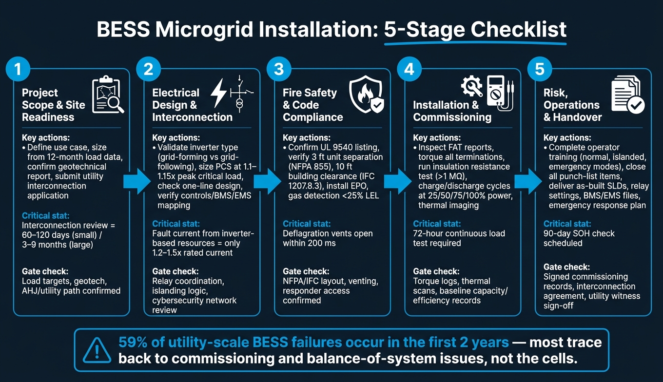
BESS Microgrid Installation: 5-Stage Checklist Overview
How to Install Indoor High Voltage ESS Battery Racks | BoostESS
sbb-itb-501186b
Quick Comparison
| Project stage | Main focus | What to confirm before moving on |
|---|---|---|
| 1. Scope and site readiness | Use case, load tiers, space, access, permits | Load targets, geotech, clearances, AHJ and utility path |
| 2. Electrical design and interconnection | Inverter type, one-line, protection, grounding, controls | PCS sizing, relay coordination, islanding logic, network setup |
| 3. Fire safety and code compliance | Listings, spacing, ventilation, EPO, signage | NFPA/IFC layout, gas detection, venting, responder access |
| 4. Installation and commissioning | Delivery checks, placement, terminations, startup tests | Torque logs, insulation tests, thermal scans, 72-hour run |
| 5. Risk, operations, and handover | Training, spares, warranty baseline, final records | Closed punch list, support files, test reports, owner acceptance |
So if you want a short version, here it is: a microgrid BESS install is not just a construction job - it’s a controls, safety, interconnection, and documentation job too.
1. Project Scope and Site Readiness Checklist
Finish this stage before you order equipment. Mistakes here tend to snowball into redesigns, permit delays, and systems that don't meet site needs once they're live.
Define the Microgrid Use Case and Performance Target
Start by pinning down what the BESS must actually do. Common jobs include backup power, peak shaving, renewable firming, black start, and islanding. That matters because each use case changes how you size the system. A setup built only for peak shaving, for example, may not have enough muscle if the site also expects it to carry the facility during a grid outage.
Use 12 months of 15-minute load data as the sizing base. Size power for the peak critical load, then add a 1.1–1.15x margin. Size energy with this formula: critical load × autonomy hours ÷ usable depth of discharge. In many projects, the target is 2–4 hours for standard outages and 4–12+ hours for high-resilience sites.
Before you lock those targets, sort loads into three tiers:
- Tier 1: life safety and IT - never shed
- Tier 2: comfort loads such as HVAC and tenant loads - shed at around 30% state of charge
- Tier 3: discretionary loads - shed immediately upon islanding
This load ranking has a direct effect on both the system power rating and the control logic the microgrid controller must run.
With the load target set, the next step is simple: make sure the site can handle the system in the real world, not just on paper.
Check Site Conditions, Space, and Access
Get a geotechnical report. It's required, and for good reason. Soil bearing capacity, drainage, frost depth, and seismic classification all shape foundation design. Skip this step, and you're asking for schedule trouble.
| Site Factor | Requirement / Standard | Key Consideration |
|---|---|---|
| Unit Separation | 3 ft (0.91 m) minimum - NFPA 855 | Can be reduced with Large-Scale Fire Test (LSFT) data |
| Building Clearance | 10 ft (3.05 m) minimum - IFC 1207.8.3 | Check manufacturer specs; exceptions may allow reduction to 3 ft |
| Slab Thickness | 10–16 in. (250–400 mm) | Verify with structural engineer based on system weight |
| Access Road Width | 13–20 ft (4–6 m) | Required for fire-service ingress |
| Vertical Clearance | 3 ft (0.91 m) | Must not be obstructed above deflagration vents |
Also check whether delivery routes can handle lowboy trailers that are 52–82 ft (16–25 m) long, and make sure crane swing radii fit inside the available footprint. If the equipment can't get in cleanly, the rest of the design doesn't mean much.
The pad should slope 1%–2% away from container footprints so water doesn't pool. Standing water speeds up corrosion and can add fire safety concerns. Temperature matters too. Lithium-ion cells perform best between 59°F and 95°F (15°C and 35°C), so cold-climate sites need frost-protected foundations with rigid insulation.
Confirm Owner, Utility, and Permitting Requirements
Submit the utility interconnection application at the start of the project, not after you've picked equipment. That's a big one. Behind-the-meter projects under 5 MW often need 60–120 days, while larger projects often take 3–9 months for interconnection and permit review. In many cases, that stretches longer than battery construction itself, which makes interconnection the main schedule driver.
Confirm the AHJ early, and verify which code edition is in force. Enforcement of NFPA 855, IFC Section 1207, and local zoning rules can shift from one municipality to the next.
Add a 30-day regulatory buffer to the schedule to absorb utility study revisions or surprise upgrade cost allocations. It also helps to bring the facility's insurance carrier in early. Providers like FM Global may require separation distances or suppression measures that go beyond local code minimums, and finding that out after procurement can get expensive.
Once scope, site conditions, and approvals are set, move into electrical design and interconnection.
2. Electrical Design and Interconnection Checklist
With site conditions and permits locked in, the next step is making sure the electrical design lines up with how the system will work in the field.
Validate BESS Technology, Inverter, and Equipment Ratings
Chemistry choice matters more than many teams expect. For stationary commercial and industrial microgrids, LFP is the standard pick because it offers strong safety performance and long cycle life. Before you specify cells, make sure they have a credible UL 9540A propagation test result.
For islanded operation, specify grid-forming inverters. Use grid-following inverters only when an external voltage and frequency reference is available.
The Power Conversion System (PCS) should be sized to 1.1–1.15x the peak critical load to cover efficiency losses and transients. Check that DC bus voltages, usually 400–800V, fit the PCS design and safety rules. If the utility feed is 4-wire, add a transformer when the BESS needs to create a neutral and provide the required neutral formation and impedance. That transformer should be sized at 110%–120% of PCS continuous power to handle overload margin. Also review switchgear and conductors for bidirectional flow, continuous charge and discharge current, and ambient derating.
Once those equipment ratings are set, the next job is to verify the one-line, protection, and grounding scheme.
Check the One-Line Design, Protection, and Grounding
The SLD should show the PCC, voltage class, breaker locations, transfer switch, and available grid capacity. Then check that layout against IEEE 1547, NEC Article 705, and NFPA 111.
Inverter-based resources only supply about 1.2–1.5x rated current during faults, which means standard overcurrent relays may not see enough fault current. That’s where a protection coordination study comes in. Plot the inverter shutdown curve against breaker trip curves and motor-starting curves, especially for fire pumps. The target is simple: the breaker closest to the fault clears first, and the inverter stays online.
Don’t trust default relay settings. Use secondary injection testing to confirm coordination.
On grounding, confirm bonding on both the DC and AC sides. Make sure the grounding method stays consistent across the PCS, transformer, and switchgear. You’ll also want to check islanding, anti-islanding, and resynchronization logic so the system can move cleanly between grid-connected and islanded modes.
After protection checks out, shift to controls, communications, and cybersecurity.
Confirm Controls, Communications, and Cybersecurity
Controls failures can stop islanding just as fast as a wiring problem. The BMS, PCS, and EMS need to map cleanly, and Modbus mapping errors are a common commissioning issue.
Before energization, verify point mapping end to end. Confirm that:
- The EMS accepts setpoints correctly
- Alarm signals reach the SCADA platform accurately
- Time stamps are synchronized across all devices using NTP or PTP
If timestamps don’t line up, post-event analysis becomes almost useless.
On cybersecurity, check that the network uses VLANs, routing, firewall rules, and whitelisting to separate BESS controls from facility IT systems. Apply the latest firmware patches to the BMS, and restrict remote access to authenticated users on segmented networks. Treat the network architecture review as a required pre-startup step, not something to circle back to right before go-live.
3. Fire Safety and Code Compliance Checklist
With the electrical design checked off, fire safety and code compliance are the last gate before energization. This is where projects often slow down. One missed life-safety item can hold up startup or, worse, leave behind a serious hazard.
These checks help confirm the system is safe to energize, not just approved to install. Use this section to make sure the installed system can be isolated, ventilated, and shut down safely before startup.
Review Applicable Codes, Listings, and Installation Standards
Start with the adopted editions of NFPA 855, NEC Articles 706 and 705, IFC Section 1207, and IBC Chapter 27. Just as important, confirm which code editions the AHJ has actually adopted.
The system should be specified as UL 9540-listed, and the battery packs should be UL 1973-listed. If the design reduces separation below 3 feet, check that UL 9540A Large Scale Fire Test data is available to support that layout.
The commissioning plan, labels, and installation method also need to match the approved permit set. If the field install drifts from the drawings, that can create problems fast.
After the code review is done, move to the physical layout. The next step is making sure spacing, ventilation, and gas-control details line up with the approved design.
Check Thermal Management, Ventilation, and Separation Distances
Verify separation distances, ventilation, and gas detection against the approved layout.
Under NFPA 855, the default separation between BESS units, and between units and walls, is 3 feet. Setbacks from buildings, lot lines, public ways, and stored combustible materials need a minimum of 10 feet under IFC 1207.8.3. That same 10-foot clearance also applies to any means of egress. Keep combustible vegetation and other obstructions out of the required fire-access zone.
For thermal management, check that liquid-cooled systems keep a cell-level temperature delta within 3 to 5°C across the container footprint. During commissioning, cycle the system and verify HVAC performance at full load for at least 60 minutes to confirm it meets OEM specs. Enclosure ventilation must run on legally required standby power under NEC 701.
Explosion control needs close attention too. Deflagration vent panels sized under NFPA 68 must be installed on the roof or upper walls, with at least 3 feet of vertical clearance above the vent surface. These panels are meant to open within 200 milliseconds to help manage internal pressure during an off-gassing event. Gas detection should be set to start ventilation before 25% of LEL.
Once spacing and ventilation are confirmed, shift to shutdown access and responder markings.
Confirm Emergency Shutdown, Signage, and Responder Coordination
Responder access and shutdown controls need to be visible, reachable, and documented.
Place a hardwired EPO station outside the BESS perimeter for responder access. Its location should be clearly marked on site drawings. Site drawings for AHJ review should also show all firefighter access points and manual release stations.
Signage comes from NEC 706.15 and NFPA 855. It must include hazard warnings, one-line diagrams, emergency contact information, and clear, durable labels. Commissioning records should also include completed Lockout/Tagout (LOTO) plans and arc flash boundary markings.
Before startup, document an Emergency Operations Plan (EOP) that covers shutdown procedures, removal of damaged equipment, and training records for staff and first responders. A tabletop drill with the local fire department before energization helps confirm that responders understand site-specific isolation points and staging areas.
Treat EPO placement, labels, and responder access as commissioning deliverables, not paperwork to handle later.
4. Installation and Commissioning Checklist
With safety and compliance signed off, the focus shifts to installation, testing, and handover.
Inspect Delivery, Placement, and Mechanical Installation
Before unloading anything, check that the FAT reports are complete and that the physical nameplates match the approved submittals. That includes capacity, voltage, and short-circuit ratings. Inspect the enclosures for any transit damage and verify insulation resistance.
Before lifting, confirm the approved lifting points. Use spreader bars to prevent structural stress. In utility-scale projects, containers commonly use ISO-standard corner castings for crane lifts. The concrete pad also needs a close check. It should stay flat within ±3 mm over 3 m and slope 1% to 2% away from the footprint so water doesn’t sit around the unit. Standing water can speed up corrosion and clog HVAC systems.
Anchor bolt placement needs to be exact. Even a 25 mm error can lead to re-drilling or epoxy-anchored retrofits. Check anchor-bolt torque during installation, then check it again after 30 days.
Once the unit is set and anchored, move to terminations, bonding, and cable routing.
Verify Electrical Installation Quality
Torque all DC busbars, battery rack connections, and both DC and AC terminations, then log each result.
Run insulation resistance tests on all battery racks and DC cabling with a 1,000 V DC megger. The minimum acceptable reading is >1 MΩ. Keep control and power cables separated by at least 300 mm (12 inches) to cut EMI risk. Confirm equipotential bonding between the racks and the container in line with IEEE 80, seal all cable entries so fire ratings stay intact, and update the single-line diagrams to show as-built status.
After terminations and testing check out, move into startup and functional verification.
Complete Startup, Functional Testing, and Baseline Records
Run controlled charge and discharge cycles at 25%, 50%, 75%, and 100% power to confirm BMS, PCS, and EMS performance. For microgrids, document the switch between grid-connected and islanded modes. This shows whether grid-forming performance holds up during islanded operation. Use thermal imaging during initial startup to spot hotspots or loose connections that torque checks may have missed.
Before final handover, complete a 72-hour continuous load test at different set points to catch early-life component issues. Record baseline capacity from 100% to 0% SOC, round-trip efficiency, and ramp response time. Those figures become the warranty enforcement baseline.
Handover documents should include:
- As-built SLDs
- Protection relay settings
- BMS/EMS files
- O&M training records
- A signed Certificate of Completion
5. Risk, Operations, and Final Handover Checklist
With commissioning done and baseline records collected, the last step is simple in theory but serious in practice: make sure the system is ready to be owned, run, and maintained over the long haul.
Confirm Operating Procedures and Maintenance Readiness
Use the commissioning baseline to set training, maintenance, and warranty checks.
Operator training should be finished before handover. All BESS technicians need documented training for normal, islanded, and emergency operating modes, including grid-forming operation when it applies. Safe operating limits for each mode should be documented before startup.
Before handover, make sure the team has records for:
- Operator training
- Safe limits for normal, islanded, and emergency modes
- A current firmware/software support plan
- Critical spares on site
- A 90-day SOH check
These items help close out owner training and warranty readiness before final acceptance.
Review Project Risks and Final Acceptance Documents
Before the owner signs off, every punch-list item needs to show closed status.
Final acceptance should confirm ONLY the documents and records needed for operation, compliance, and warranty support.
| Category | Essential Deliverables |
|---|---|
| Documentation | As-built SLDs, as-left settings, O&M manuals, software licenses, signed commissioning records |
| Testing | FAT/SAT reports, baseline capacity test, round-trip efficiency results |
| Regulatory | Interconnection agreement, grid model validation certificate, building permits, COD approval, utility witness sign-off |
| Operations | Operator training logs, spare parts inventory, maintenance schedules, firmware version logs, BMS/EMS config files, firmware support plan |
| Safety | Emergency shutdown procedures, fire-suppression test records, E-stop validation, emergency response plan, arc flash study |
The baseline capacity test at initial energization matters a lot because it becomes the reference point for later annual capacity tests under the warranty. That’s why it needs to be run under the exact conditions listed in the warranty.
These closeout items finish the installation phase and move the project into the final pre-energization review.
FAQs
How do I choose the right BESS size?
Use a four-step approach to balance performance and cost:
- Review 12 months of 15-minute load data to spot peak demand, critical loads, and outage duration.
- Assess existing generation, such as solar PV, and check details like generator start-up time.
- Size kW around the largest load step or the demand-charge threshold, and size kWh around your target islanding duration.
- Choose controller hardware that can manage site breakers and sensors.
For C&I projects, a common rule of thumb is a 0.5C to 0.25C rate.
What permits take the longest?
BESS permitting often takes 12 to 18 months from pre-application to notice to proceed. In practice, the biggest slowdowns usually come from hard-to-predict back-and-forth with the authority having jurisdiction (AHJ).
One of the main pain points is inconsistent interpretation of standards like NFPA 855. When that happens, teams can get stuck in redesign loops that add cost and put the schedule at risk.
The good news? Timelines can often be cut down with a thorough feasibility audit, a pre-application meeting, and one fully coordinated submission.
What should pass before energization?
Before energization, the battery energy storage system must pass both mechanical and electrical checks to confirm safe condition and system integrity.
This usually includes:
- Torque checks on DC busbars, battery rack connections, and AC cabling
- Insulation resistance testing on battery racks and DC cabling
- Grounding verification for equipotential bonding
You’ll also want to confirm that sensor calibration is correct and that key safety and control functions are working as intended. That includes fire suppression and gas detection, E-stop circuits, protection relay secondary injection tests, and stable communication between the battery management, power conversion, and energy management systems.


