
Overload Protection in Power Generation Systems
Overload protection is essential for safeguarding power generation systems from damage caused by excessive current. It prevents overheating of critical components like windings and bearings and ensures that faults are isolated to minimize system disruptions. Two primary methods - Overcurrent Relays and Thermal Overload Relays - offer different approaches to achieving this protection.
Key Points:
- Overcurrent Relays: Use electronic sensors to detect and clear short-circuit faults quickly. They are precise, programmable, and suitable for dynamic systems but come with a higher cost.
- Thermal Overload Relays: Use bimetallic strips to protect against prolonged overloads. They are cost-effective and suitable for stable load applications but are slower and sensitive to ambient temperature changes.
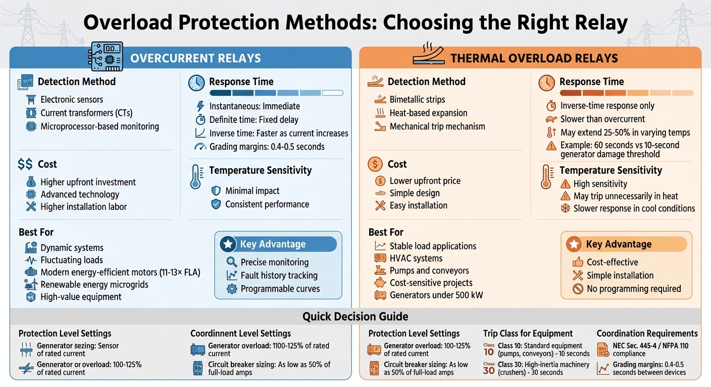
Quick Comparison:
| Feature | Overcurrent Relays | Thermal Overload Relays |
|---|---|---|
| Detection Method | Electronic sensors, current transformers | Bimetallic strips (heat-based) |
| Response Time | Fast (instantaneous/inverse time) | Slower, inverse-time response |
| Cost | Higher upfront cost | Lower upfront cost |
| Best Use Case | Dynamic systems, modern equipment | Stable load applications, cost-sensitive projects |
| Temperature Sensitivity | Minimal | High |
Overcurrent relays are ideal for systems with fluctuating loads, while thermal relays are better suited for simpler, steady systems. Selecting the right method depends on system requirements, budget, and the need for precision.
Overcurrent vs Thermal Overload Relays Comparison Chart
1. Overcurrent Relays
Detection Method
Overcurrent relays work by monitoring current levels using current transformers (CTs). These transformers reduce high primary currents to manageable secondary levels, typically 1A or 5A, making them easier to measure and analyze. The relay then compares the measured RMS current to pre-set thresholds or programmed protection curves. If the current exceeds these limits, the relay activates and trips the circuit breaker.
Modern microprocessor-based relays take this process a step further by using summing algorithms to compare real-time current measurements with stored thermal damage curves. This ensures the system delivers the maximum allowable current before tripping. To avoid unnecessary interruptions caused by transient surges, such as motor inrush currents, these relays include time-delay mechanisms. This feature helps differentiate between temporary fluctuations and actual faults.
Response Time
Once the relay detects an overcurrent, the next crucial factor is how quickly it responds. The response time depends on the type of relay being used:
- Instantaneous relays respond immediately when current exceeds the threshold. They are ideal for protecting against severe short circuits.
- Definite time relays trip after a fixed delay, regardless of the fault's magnitude. However, for high-magnitude faults near the source, this fixed delay can result in slower fault clearing.
- Inverse time relays provide a more flexible response. Their trip time decreases as the fault current increases, enabling faster tripping for higher fault currents.
In radial systems, definite time grading is often used. For example, a source relay might have a delay of 1.7 seconds, allowing downstream relays - set at intervals of 0.2s, 0.7s, and 1.2s - to clear faults first. Standard grading margins between adjacent circuit breakers typically range from 0.4 to 0.5 seconds.
Selectivity
Effective selectivity ensures that only the protective device closest to a fault operates, isolating the affected circuit while keeping the rest of the system running smoothly. This is achieved through grading, where relays are calibrated with specific time and current settings. For proper coordination, the relay farthest from the power source is set with lower current thresholds compared to those upstream.
"Selective coordination means that, even under the worst-case available fault, a fault in a smaller feeder originating below the level of the main generator protection will... open and clear that fault safely [while] all other overcurrent devices further upstream will stay closed." - Lawrence Bey, Author, EC&M
Coordination is typically verified using Time-Current Curves (TCCs), which graphically represent the relationship between operating time and current magnitude. For generator protection, relay settings must align with the manufacturer's generator damage curve, which dictates how much overload current a generator can handle over time without sustaining damage.
Applicability
Proper relay sizing plays a key role in optimizing system performance. For example, when using thermal-magnetic circuit breakers for generator protection, they may need to be sized as low as 50% of the generator's full-load amps to ensure effective protection. While this approach limits capacity, it offers precise protection that safeguards the generator's integrity. These features make overcurrent relays an essential component in designs that balance protection with operational efficiency.
sbb-itb-501186b
Overcurrent Protection Basics | How to Set Overcurrent Elements in Protection Relays
2. Thermal Overload Relays
Thermal overload relays take a mechanical, heat-based approach to protect against prolonged overloads, unlike overcurrent relays that rely on electronic sensors for quick fault clearance.
Detection Method
These relays operate using the heating effect of the electric current on bimetallic strips - two metals bonded together that expand at different rates when heated. As current flows, the strips heat up and bend. Once they reach a specific deformation threshold, the relay's mechanical trip mechanism activates, cutting the power. While this approach is more affordable initially, its slower response time and sensitivity to ambient temperature changes can be limiting.
Response Time
Thermal overload relays follow an inverse-time response. This means they allow brief overloads but trip faster as the excess current increases, disconnecting the circuit before thermal damage occurs. However, a mismatch in response time can be a major issue in power generation. For instance, a typical thermal-magnetic breaker might take 60 seconds to trip under conditions that could harm a generator in just 10 seconds. The relay's effectiveness depends on how closely its tripping curve matches the generator's damage threshold. Modern microprocessor-based systems improve this by using algorithms to compare real-time RMS current with preloaded thermal protection curves, ensuring a more precise response.
Applicability
Thermal overload relays are ideal for applications with steady, predictable load patterns, such as HVAC systems, pumps, and conveyors. Their lower upfront cost makes them a practical choice for basic motor protection. Engineers often set generator overload protection levels between 100% and 125% of the rated current (considering the rated kW and power factor).
In systems where selective coordination is required - such as those governed by NEC Sec. 445-4 or NFPA 110 - thermal protection must include grading margins of 0.4 to 0.5 seconds. This ensures downstream devices clear faults before the generator's main protection trips. For more dynamic or critical equipment that demands advanced diagnostics and precision, electronic overload relays are a better option, despite their higher cost. Thermal overload relays, however, remain a cost-effective part of broader overload protection strategies, especially in less demanding applications.
Advantages and Disadvantages
Both types of relays play specific roles in power generation protection, each with its own balance of cost, performance, and reliability.
Thermal overload relays are the more affordable option upfront, making them ideal for cost-sensitive projects. According to Schneider Electric, "Switches based on thermal overload provide a lower upfront price than alternative models". Their simple design makes them easy to install without requiring specialized programming. However, their sensitivity to ambient temperature can be a drawback. For example, in high ambient temperatures, they may trip unnecessarily, while in cooler conditions, their response might lag. This thermal inertia can extend trip times by 25–50%, depending on the unit's operating temperature.
On the other hand, overcurrent relays come with a higher initial cost due to their advanced microprocessor technology. Schneider Electric highlights this by stating, "Electronic overload relays have higher cost points because they include advanced functional capabilities". While these relays require skilled installation and incur greater labor costs, they offer precise monitoring, the ability to track fault history, and greater stability in varying temperatures. As Schneider Electric notes, "Electronic relay systems monitor circuit data while tracking past failures, which results in improved maintenance capabilities".
The choice between these relays depends on the system's specific needs. Thermal relays are a good fit for stable load applications, such as HVAC systems and pumps, where cost is a primary concern. In contrast, overcurrent relays excel in environments with fluctuating loads or where precision and diagnostics are essential. For instance, they are particularly effective in systems using modern energy-efficient motors, which have locked rotor currents of 11–13× Full Load Amps compared to older motors with 6–8× FLA.
Conclusion
Choosing the right relay depends entirely on your system's needs. Thermal overload relays rely on bimetallic strips that bend when heated, providing straightforward but slower protection. On the other hand, overcurrent relays offer faster and more precise protection, often with digital monitoring.
Beyond their operational differences, environmental factors also play a role. Thermal relays can be influenced by ambient temperature changes, while electronic overcurrent relays maintain consistent performance regardless of temperature variations.
For smaller generators (under 500 kW), thermal overload relays paired with molded case circuit breakers are often sufficient. However, in renewable energy microgrids, where sources frequently connect and disconnect, microprocessor-based overcurrent relays are better suited. These relays offer programmable curves and real-time monitoring, making them ideal for managing the complexities of such systems.
Relay selection also depends on the type of equipment being protected. High-inertia machinery like crushers requires Class 30 relays, which trip within 30 seconds, while standard equipment like pumps and conveyors typically use Class 10 relays, which trip within 10 seconds. Additionally, modern energy-efficient motors often have locked rotor currents of 11–13× Full Load Amps, compared to older motors' 6–8× FLA. This difference impacts how protection settings should be configured.
For systems with stable loads and tighter budgets, thermal relays are a cost-effective solution. However, for dynamic systems or high-value equipment, investing in microprocessor-based overcurrent relays ensures better protection and reduces the risk of unnecessary trips that could disrupt operations.
FAQs
How do I choose relay settings that match a generator’s damage curve?
To properly align relay settings with a generator's damage curve, it's essential to evaluate the generator's time-current characteristics and its specific protection needs. The goal is to ensure that the relay settings correspond with the generator's ability to handle fault currents without exceeding its damage limits.
Here’s how to approach it:
- Review the manufacturer’s damage curve: This curve outlines the generator's tolerance to fault currents over time. It serves as the baseline for setting protective limits.
- Analyze the time-current characteristic curve (TCC): Compare the generator’s TCC with the relay's operating characteristics to ensure compatibility.
- Set trip points and delays: Configure the relay to trigger at levels that provide effective protection against overloads and faults, while staying below the generator's damage threshold.
By carefully following these steps, you can achieve reliable protection for the generator without compromising its operational integrity.
What prevents overcurrent relays from tripping on motor inrush?
Overcurrent relays prevent unnecessary tripping during motor inrush by employing time delay settings or overload protection features. These tools allow the relay to distinguish between the brief surge of current that occurs when a motor starts and prolonged overcurrent situations, like sustained overloads or electrical faults.
How can I reduce nuisance trips caused by ambient temperature?
To minimize unnecessary trips triggered by ambient temperature changes, it’s crucial to choose and adjust overload relays correctly. When temperatures run high, thermal overload devices may trip earlier than intended. Proper calibration to accommodate these fluctuations ensures they perform dependably.


