
Troubleshooting Medium Voltage Motor Control Failures
Medium voltage motor control systems power industrial equipment like compressors, pumps, and fans operating at 2,400V or higher. Failures in these systems can halt operations, causing downtime and costly repairs. This guide outlines common failure causes and troubleshooting steps to quickly restore functionality.
Key Takeaways:
- Common Issues: Electrical overheating, mechanical wear, and insulation breakdown.
-
Troubleshooting Steps:
- Diagnose overheating by checking current draw, voltage imbalances, and airflow.
- Address mechanical wear by inspecting bearings, alignment, and connections.
- Test insulation resistance and repair cracks or moisture damage.
- Relay and Circuit Failures: Inspect relays for false trips or degradation, and verify control circuit voltages.
- Maintenance Tips: Regular inspections, tightening connections, and using quality components reduce failures.
By following these steps, you can minimize disruptions and maintain system reliability.
Motor Voltage Imbalance Troubleshooting and Effects Explained
sbb-itb-501186b
Common Causes of Motor Control Failures
Common Causes of Medium Voltage Motor Control Failures: Statistics and Distribution
Medium voltage motor control systems often fail due to three main issues: electrical overheating, mechanical wear, and insulation breakdown. By understanding these problems, you can quickly identify faults and minimize costly repairs.
Electrical Overheating
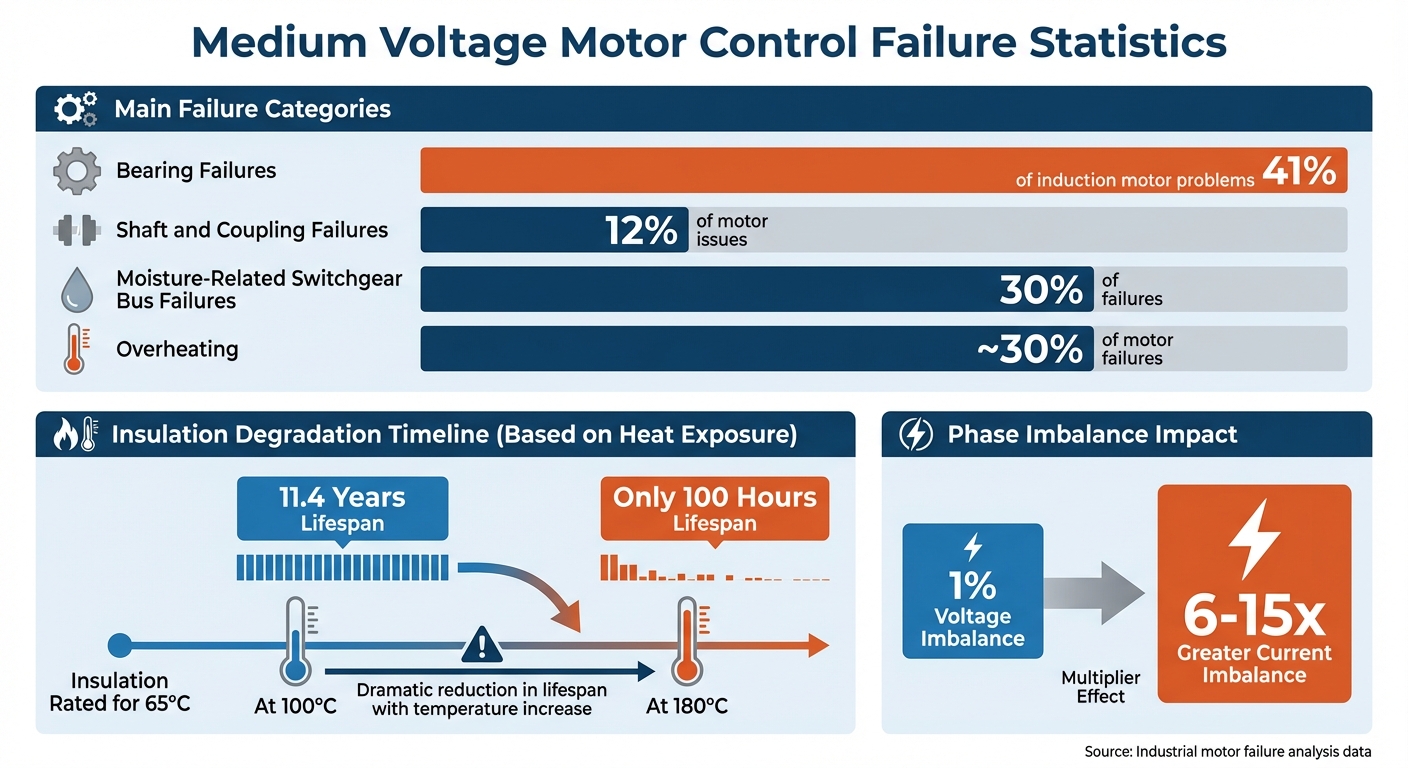
Electrical overheating happens when systems operate beyond their capacity, experience phase imbalances, or suffer from inadequate ventilation. These conditions generate excessive heat, which can quickly damage components. Phase imbalances are especially harmful - a small voltage imbalance from something as simple as a loose connection can lead to current imbalances 6 to 15 times greater than the voltage difference. Additionally, blocked air vents, faulty cooling fans, or an undersized motor struggling with its load can trap heat within the system.
To spot overheating, compare the motor’s current draw to its nameplate specifications and ensure the voltage stays within +5% to -10% of the rated value. Regular physical inspections of air vents, along with thermal scans of motor housings, can help detect blocked airflow or hot spots before significant damage occurs. Once electrical issues are addressed, it’s important to consider mechanical factors that can also degrade motor control systems.
Mechanical Wear and Tear
Mechanical components in motor control systems naturally wear down over time due to repeated use, vibration, and misalignment. Bearing failures, for example, account for 41% of induction motor problems. Worn bearings generate friction and heat, and failing bearings often produce grinding or squealing noises. Loose electrical connections in contactors and breakers can also develop high resistance, leading to dangerous arcing. Burnt or pitted contacts may be visible during inspections.
Shaft and coupling failures, which account for another 12% of motor issues, often result from misalignment between the motor and its load. Additionally, vibration and thermal cycling can loosen terminal connections over time. Signs of trouble include discolored insulation or melted material near terminal lugs. While mechanical wear is a major concern, insulation breakdown is another critical factor to monitor.
Insulation Breakdown
Insulation deteriorates over time, especially when exposed to moisture and high temperatures. Moisture alone contributes to 30% of switchgear bus failures, as it seeps into small cracks in aging insulation and creates unintended electrical paths between conductors. Heat also accelerates insulation aging - for example, insulation rated for 65°C lasts 11.4 years at 100°C but only 100 hours at 180°C.
To catch insulation problems early, use a megohmmeter to measure insulation resistance and inspect terminal boxes for signs of tracking, moisture, or visible cracks. These proactive measures can help prevent system-wide failures and keep your motor control systems running smoothly.
Troubleshooting Techniques for Motor Control Failures
Once you've pinpointed the potential cause of a motor control failure, the next step is to dive into diagnostic and repair procedures. These steps will help confirm the issue and safely restore the system to working order.
Diagnosing Overheating Problems
Start by checking the ambient temperature - it shouldn't exceed the motor's rated limit, which is typically 104°F (40°C). Next, inspect air vents, cooling fans, and filters for any dust or debris that might obstruct airflow. Use a clamp meter to measure the motor's current draw and compare it to the full-load current listed on the nameplate. If the current exceeds the rated value, the motor might be overloaded or experiencing mechanical resistance.
Verify the incoming voltage - it should stay within +5% to -10% of the motor's rating. Also, check for phase voltage imbalance; even a 1% imbalance can lead to excessive heating. An infrared camera can help identify any hot spots on the motor frame, bearings, or electrical connections during operation. Perform an insulation resistance test at 1,000V for motors rated between 1,000 and 2,500V. Healthy insulation should show readings in the hundreds of megohms, while values below 1 megohm indicate a high risk of failure. Measure the DC resistance between phases (T1–T2, T2–T3, T1–T3); an imbalance over 5% could point to damage or poor connections.
If the motor is severely overheated, allow it to cool completely before re-energizing to avoid further insulation damage. Tighten all electrical terminals to the manufacturer's torque specifications, as loose connections can cause localized heating. In particularly dusty environments, establish a regular cleaning routine for cooling fins and fans to maintain proper airflow.
Once electrical issues are ruled out, shift your attention to the motor's mechanical components.
Fixing Mechanical Failures
After confirming that electrical parameters are normal, check the mechanical components for issues. Inspect contactors and breakers for burnt or pitted contacts, and ensure all power connections are tightened to the manufacturer's torque specifications to prevent arcing and contactor failure. If the motor operates in a high-vibration environment, consider installing anti-vibration hardware. Replace any discolored or melted lugs or wiring as needed.
Use precision alignment tools to check for shaft misalignment between the motor and its load, as misalignment can increase friction and wear on bearings. Re-lubricate the bearings using only grease specified by the original equipment manufacturer (OEM) to avoid contamination. For belt-driven systems, confirm the motor is designed to handle significant radial loads to prevent damage to the shaft and bearings. Vibration analysis can serve as an early warning system to detect mechanical or electrical imbalances before they cause significant damage.
Once mechanical issues are addressed, turn your focus to insulation and arcing faults.
Repairing Insulation and Arcing Faults
Visible signs of insulation erosion, bare copper, or carbon tracking might not always align with standard insulation resistance test results. As Tom Garrett, Automation Engineer at Industrial Monitor Direct, explains:
"The disconnect between acceptable IR/PI results and visible physical degradation is common in aging machines and reflects the limitation of bulk insulation testing".
To address these limitations, consider using surge comparison testing to detect inter-turn faults and Partial Discharge (PD) testing to identify localized voids. If moisture is present, bake the windings at 302°F (150°C) for 12–16 hours to thoroughly dry them before applying new insulation. Use dry-ice or bead blasting to remove loose material and conductive contaminants without damaging the motor's structure. Apply Vacuum Pressure Impregnation (VPI) with Class F or H varnish to seal micro-cracks and prevent further deterioration. Installing surge protection devices can also help reduce voltage spikes and minimize future insulation stress.
Before putting the motor back into service, perform a Dielectric Absorption Ratio (DAR) test to ensure the value is greater than 1.5.
Maintaining Protective Relays and Control Circuits
Protective relays and control circuits play a key role in ensuring system stability. When they fail, the entire system can face serious disruptions. Regular maintenance is essential to avoid unexpected downtime. Much like diagnosing motor issues, maintaining relays and control circuits requires a methodical, step-by-step approach.
Identifying Relay Malfunctions
Frequent nuisance tripping is often a sign of relay problems. This can happen due to CT saturation during high phase currents, surge discharges through arresters, or uneven primary currents triggering false alarms. If instantaneous ground-fault relays (Device 50G) are causing frequent false trips, you might consider switching to time-overcurrent ground-fault relays (Device 51G) or introducing a time delay to filter out momentary surges.
Physical degradation is another common issue. Signs like charred PCB components, swollen capacitors, or melted insulation around terminal lugs often point to loose connections causing localized overheating. Using an infrared camera during routine inspections can help detect these hot spots early, preventing more significant failures.
If a relay fails to actuate, you might notice a persistent hum without proper operation. This could indicate that the relay or soft starter isn’t firing on all phases. During maintenance or commissioning, secondary injection testing can be useful. By passing a test current through the window of a zero-sequence CT, you can identify open circuits in the CT secondary or its wiring. As Edvard Csanyi, Electrical Engineer, explains:
"Because normally the relays do not carry current, an open circuit in a CT secondary or wiring to a relay can be discovered by this overall testing".
Understanding how relays behave under different conditions is a crucial step in addressing control circuit issues.
Fixing Control Circuit Failures
Control circuits operate at lower voltages than power circuits, relying on a step-down transformer to function correctly. If a motor starter doesn’t engage, check the control transformer’s input and output voltages to confirm the circuit is receiving the proper stepped-down voltage. Addressing power and interface issues systematically can help pinpoint the fault.
Loose connections are a frequent cause of control circuit failures. Ensure all connections are tightened to the manufacturer’s torque specifications. Many manuals also recommend re-torquing after an initial break-in period. Loose terminals can create resistance, leading to phase imbalances or single-phasing conditions.
For modern electronic controllers, unresponsive behavior or inconsistent motor output might stem from firmware or software issues. Use the manufacturer’s tools to reinstall or update firmware to resolve any logic errors. Additionally, protecting relay enclosures with appropriate NEMA or IP-rated covers can guard against dust and oil contamination - common culprits behind internal short circuits in sensitive electronics.
A solid understanding of relay failure modes is essential for proper selection and calibration.
Comparison of Common Relay Types
| Relay Type | Typical Failure Modes | Detection and Repair |
|---|---|---|
| Overcurrent Relay (50/51) | Nuisance tripping from inrush; incorrect settings causing failure to trip | Use a clamp meter for current measurement; perform a coordination study; recalibrate settings based on motor nameplate |
| Differential Relay (87) | CT mismatch/saturation; open circuit in secondary wiring | Perform secondary injection testing by passing a test current through the CT window; verify CT ratios and inspect wiring |
For medium-voltage applications, ground-fault relays should typically be set within a primary current range of 10 A to 30 A. If Device 50G pickup levels are set too low, frequent false trips can occur. Adjusting the settings or switching to Device 51G can help provide better surge protection.
Sourcing Quality Electrical Components for Long-Term Solutions
Once you’ve diagnosed and repaired the issue, the next step to ensuring lasting reliability is to source high-quality components. These parts do more than just address immediate electrical or mechanical problems - they’re designed to withstand tough conditions. Dust and moisture, for instance, are common culprits behind component failures, but well-designed parts can resist these stresses effectively. Reliable connections also play a key role by maintaining stable resistance levels and preventing dangerous heat buildup. Additionally, using protective relays like Device 87 can detect low-level faults early, limiting damage to motor windings. Pairing these with precision overcurrent protection devices helps block excessive current and guards against short circuits.
Using Platforms Like Electrical Trader
Finding dependable sources for medium voltage components is crucial for maintaining system reliability. One such platform, Electrical Trader (https://electricaltrader.com), offers a range of new, used, and reconditioned medium voltage equipment. Their inventory includes motor control centers, circuit breakers, and soft starters. They also feature trusted brands like Allen-Bradley, Westinghouse, and ABB.
This approach can help you save on costs without sacrificing performance. Once you’ve secured a reliable supplier, carefully evaluating the specifications of each component ensures your system’s long-term health.
Evaluating Component Specifications
When evaluating components, start by confirming that their ratings match your system’s real-world operating conditions. Voltage ratings, for example, should align with what your system requires. For motors paired with variable frequency drives (VFDs), make sure the components are inverter-duty rated. This ensures they can handle the voltage spikes caused by fast PWM switching and the extra heat from harmonic distortion.
If you’re considering used components, request detailed maintenance records, including service history and circuit breaker operation counts. It’s also critical to check that voltage ratings - such as 4.16kV, 7.2kV, or 13.8kV - and interrupting capacities fit your power system’s needs. Before installation, conduct diagnostic tests to confirm performance. For older components, verify the availability of replacement parts to avoid future supply chain headaches.
Environmental factors matter too. Ensure components have the right NEMA or IP ratings for your installation’s conditions, accounting for temperature, humidity, altitude, and potential contaminants. Components with hydrophobic insulation surfaces are particularly effective at resisting moisture absorption and voltage stresses, which helps prevent breakdowns. Additionally, regular infrared inspections can catch issues like overheating connections or partial discharges before they escalate into major system failures.
Conclusion
Medium voltage motor control systems require a focused approach that blends consistent maintenance, thorough troubleshooting, and careful selection of components. As Alex Roderick, Senior Electrical Engineer, explains:
"Troubleshooting is the systematic elimination of the various parts of a system to find a malfunctioning element".
This structured approach helps prevent minor issues from snowballing into major disruptions, ensuring equipment runs smoothly and efficiently.
Routine maintenance plays a key role in keeping systems reliable. Regularly inspect voltage levels, motor loading, and protective devices to catch potential issues early. It's worth noting that overheating alone causes about 30% of motor failures, and when combined with bearing problems and insulation breakdown, these issues account for over 43% of industrial motor failures.
When troubleshooting is necessary, start by examining primary access points and use tools like thermal imaging to detect electrical hotspots. Always adhere to lockout/tagout protocols before working on energized equipment. By staying proactive with maintenance and addressing faults quickly, you can extend the lifespan of your motor control systems and maintain safe operations.
The quality of components also plays a huge role in system performance. Whether you're replacing a soft starter or upgrading to inverter-duty motors, ensure the components meet your system's specific requirements. For medium voltage needs, platforms like Electrical Trader (https://electricaltrader.com) offer a range of new, used, and reconditioned equipment from trusted manufacturers. Balancing cost and performance is essential for maintaining reliable and safe operations over the long term.
FAQs
When should I suspect a voltage imbalance is causing overheating?
If you notice that line-to-line voltages differ by more than 1%, it’s a clear sign of a voltage imbalance. This issue can lead to motor overheating, which often results in serious operational problems. It’s important to address this quickly to prevent additional damage.
What tests detect insulation damage that a megohmmeter might miss?
Tests such as partial discharge (PD) monitoring and impulse endurance testing are excellent for spotting insulation problems that a megohmmeter might miss. These techniques are particularly useful for identifying localized issues, like degradation, voids, or surface stress, which can go undetected in standard bulk insulation resistance measurements.
How can I stop protective relays from nuisance tripping?
To avoid nuisance tripping, it's important to align relay settings with the motor's actual operating conditions. Fine-tune the sensitivity and time delay to minimize false trips caused by transient conditions. Make sure the relay is compatible with the motor's load characteristics, and consider applying filtering techniques if required. Regularly maintaining and testing the relays is equally important to keep them functioning correctly and prevent unnecessary interruptions.


