




NEC Bonding Conductor Requirements: Quick Guide
If the bond path is wrong, the breaker may not trip when a fault hits. That’s the core point of this guide: bonding is the metal fault path back to the source, while grounding to earth is a different job.
Here’s the short version in plain English:
- I use bonding to keep metal parts electrically connected.
- I use a main bonding jumper at service equipment only.
- I use a system bonding jumper at a separately derived system source or first disconnect - not both.
- I use a supply-side bonding jumper on the line side of the disconnect, or between an SDS source and first disconnect.
- I use an equipment bonding jumper on the load side where metal continuity is interrupted.
- I size main, system, and supply-side jumpers by conductor size under NEC Table 250.102(C)(1).
- I size equipment bonding jumpers by OCPD rating under Table 250.122.
- If parallel conductors push the total above 1,100 kcmil copper or 1,750 kcmil aluminum, I apply the 12.5% rule.
- I do not bond neutral to ground again in a downstream subpanel.
A few points matter most on the job:
- One wrong neutral-to-ground bond can put current on metal raceways and enclosures.
- Two sizing methods control most jumper work under Article 250.
- Structural steel bonding has a cap of 3/0 AWG copper or 250 kcmil aluminum in the case covered here.
- For branch circuits, metal boxes and receptacle enclosures are often tied in through the EGC, with No. 12 or No. 14 AWG copper commonly seen on 15 A to 20 A circuits.
This guide sums up where each bonding jumper goes, how NEC sizes it, what materials are allowed, and where these rules show up in the field - like services, transformers, piping, steel, panels, and receptacle boxes.
NEC Grounding and Bonding Conductor Sizing Explained
sbb-itb-501186b
Bonding Conductors Under NEC Article 250
NEC Article 250 defines a bonding conductor or jumper as a conductor used to connect metal parts so they stay electrically continuous and provide a low-impedance fault path. Put simply, it’s the conductor or strap that keeps metal parts tied together electrically. That continuity gives fault current a low-impedance path back to the source so the overcurrent device can operate.
The earth is not an effective ground-fault current path. What trips the breaker is a properly bonded, low-impedance path back to the source.
These NEC terms get mixed up all the time, so this table separates them by what each one does.
| NEC Term | Primary Purpose | Key Distinction |
|---|---|---|
| Bonding conductor / jumper | Ensure continuity between metal parts | Focuses on the fault path, not the earth connection |
| Equipment grounding conductor (EGC) | Carry fault current on load-side circuits | Part of the effective ground-fault current path |
| Grounding electrode conductor (GEC) | Connect the system to the grounding electrode | Connects to earth; not the main fault-clearing path |
| Main / system bonding jumper | Tie the grounded conductor to the EGC at the source | Bond only at the service or separately derived system source |
| Supply-side bonding jumper | Maintain continuity on the supply side | Used ahead of the load-side overcurrent device |
How Bonding Differs From Grounding
Bonding connects metal parts so they stay at the same electrical potential and form a continuous fault-current path. Grounding connects the system to earth through a grounding electrode conductor and grounding electrode system.
At the service, the main bonding jumper connects the grounded conductor to the equipment grounding system and the metal enclosure. Then a grounding electrode conductor connects that assembly to earth. On the load side, such as in panelboards and subpanels, neutrals and equipment grounding conductors stay separate. The enclosure is bonded to the equipment grounding path, but there’s no extra neutral-to-ground bond.
Where Bonding Is Commonly Required
NEC requires bonding in a few common spots. Service disconnects need a main bonding jumper that connects the grounded conductor, equipment grounding conductors, and the metal enclosure. That’s what makes fault clearing possible at the service level.
Transformers and separately derived systems need a system bonding jumper at the secondary source, along with a supply-side bonding jumper to keep continuity through associated raceways and enclosures.
Switchboards and panelboards must have their metal enclosures bonded to the equipment grounding conductor system. If concentric knockouts or non-bonding fittings break continuity, equipment bonding jumpers put that path back in place.
Exposed structural steel that can become energized must be bonded to the electrical system so a fault to the structure clears in a safe way. Interior metal piping - including water and gas lines - must also be bonded to prevent dangerous touch voltages and help faults clear the way they should. For example, you might bridge a dielectric union or use a bonding bushing where a knockout interrupts metal continuity.
With the required bond points identified, the next step is choosing the right jumper type.
Types of Bonding Jumpers and Where Each One Is Used
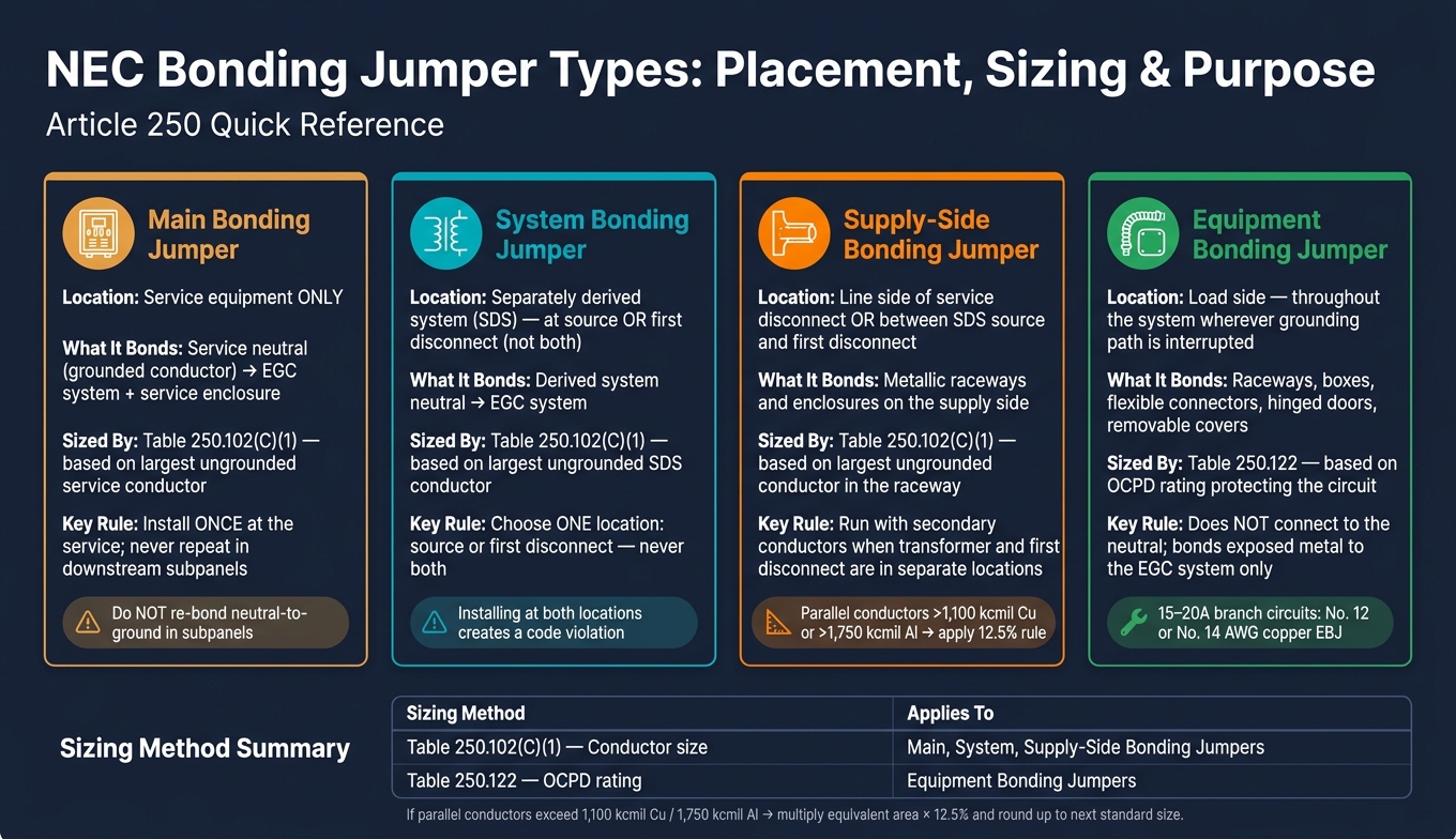
NEC Bonding Jumper Types: Placement, Sizing & Purpose at a Glance
Once you identify the bond point, the next step is simple: match it to the right jumper type. The NEC defines four types of bonding jumpers. Each one keeps the fault-current path continuous at a different point in the electrical system.
Main and System Bonding Jumpers
The main bonding jumper connects the grounded conductor, or neutral, to the equipment grounding conductors and the service enclosure. That bond ties the service neutral to the equipment grounding system and helps fault current get back to the source.
A system bonding jumper does the same job for a separately derived system. It goes at the source or at the first disconnect. You can install it at either spot, but not both.
One field mistake shows up again and again: adding a neutral-to-ground bond in a downstream subpanel. That creates an unwanted parallel path for neutral current. When that happens, objectionable current can end up on metal raceways and equipment frames.
The next split matters just as much: some jumpers are used on the supply side, while others maintain continuity on the load side.
Supply-Side and Equipment Bonding Jumpers
After the source bond is in place, the job shifts to keeping continuity intact on both sides of the system.
A supply-side bonding jumper is installed on the line side of the service disconnect, or between a separately derived source and its first disconnect, to bond supply-side raceways and enclosures. If the transformer and the first disconnect are in different locations, run the supply-side bonding jumper with the secondary conductors.
Equipment bonding jumpers handle breaks in the load-side equipment grounding path. They’re used where the grounding path would otherwise be interrupted, such as at flexible metal conduit, concentric knockouts, hinged doors, and removable covers. A bonding bushing with a wire jumper at a concentric knockout is a common example. These jumpers do not connect to the neutral. Their job is to keep exposed metal bonded to the equipment grounding system.
Use the table below as a quick placement check.
| Jumper Type | Location | What It Bonds |
|---|---|---|
| Main bonding jumper | Service equipment only | Service neutral → EGC system + service enclosure |
| System bonding jumper | Separately derived source or first disconnect | Derived system neutral → EGC system |
| Supply-side bonding jumper | Line side of the service disconnect or between a source and first disconnect | Metallic raceways and enclosures on the supply side |
| Equipment bonding jumper | Load side, throughout the system | Raceways, boxes, flexible connectors, doors, covers |
How NEC Requires Bonding Conductors to Be Sized
After you identify the jumper type, the next step is sizing it under the right NEC rule. The NEC uses two sizing methods here: one is based on conductor size, and the other is based on the overcurrent protective device (OCPD) rating.
| Bonding Conductor Type | NEC Sizing Reference | Controlling Factor |
|---|---|---|
| Main bonding jumper | Table 250.102(C)(1) | Largest ungrounded service conductor or combined circular-mil area of parallel conductors |
| System bonding jumper | Table 250.102(C)(1) | Largest ungrounded SDS conductor or combined circular-mil area of parallel conductors |
| Supply-side bonding jumper | Table 250.102(C)(1) | Largest ungrounded conductor in the raceway or cable |
| Equipment bonding jumper | Table 250.122 | OCPD rating protecting the circuit |
Sizing Main, System, and Supply-Side Bonding Jumpers
Main, system, and supply-side bonding jumpers are sized by conductor size, not by breaker rating. Start with the largest ungrounded conductor in the service or system. Then use Table 250.102(C)(1) to find the minimum bonding jumper size.
If the conductors are installed in parallel, add the circular-mil area of the largest ungrounded conductors in each set. Use that combined area when you enter Table 250.102(C)(1).
There’s one extra rule once the total gets big enough. If the total is more than 1,100 kcmil copper or 1,750 kcmil aluminum, apply the 12.5% rule. Multiply the equivalent area by 0.125 to get the minimum bonding jumper area, then round up to the next standard conductor size.
Sizing Equipment Bonding Jumpers for Enclosures and Raceways
Equipment bonding jumpers are different. These are sized by the OCPD rating using Table 250.122. From there, read the minimum copper or aluminum size.
If the ungrounded conductors are upsized, the equipment bonding jumper also needs to be upsized in proportion.
Sizing is only one piece of code compliance; material and installation rules come next.
Materials, Installation Rules, and Project Application
Once you size a bonding conductor, the NEC also tells you what it can be made from and how it has to terminate. Bonding jumpers can be copper, aluminum, copper-clad aluminum, or another NEC-compliant material. They can be installed as wire, bus bar, or even a screw, depending on the use case. Copper is the go-to choice in damp or corrosive areas. Aluminum and copper-clad aluminum are allowed in dry indoor spaces, but only when the connectors and lugs are listed for aluminum use and the conductor stays away from masonry and direct earth contact.
Terminations have to use listed connectors, such as pressure lugs, compression fittings, or terminal bars. Exothermic welding is also used when a permanent bond makes sense. In panelboards and switchboards, factory-installed grounding and bonding bars already come with listed lugs for this job. Still, it’s smart to check that the bars and lugs are listed for the conductor material and size you plan to use. No. 6 AWG and larger conductors must be protected from physical damage in RMC or another suitable raceway. You see these rules most often when bonding piping, structural steel, and enclosures.
Bonding Metal Piping, Structural Steel, and Receptacle Enclosures
Interior metal water and gas piping must be bonded with a conductor sized under Table 250.102(C)(1). In most jobs, that conductor is connected near the point where the piping enters the building, using a listed pipe bonding clamp or an exothermic weld. The routing matters too. Don’t run the jumper where it can get hit, scraped, or pinched. If damage is possible, put it in conduit.
Exposed structural steel and building metal frames follow that same table, but there’s a cap: the bonding jumper does not have to be larger than 3/0 AWG copper or 250 kcmil aluminum. At the steel itself, exothermic welding and listed mechanical clamps are common ways to terminate the connection. This ties the steel frame into the grounding electrode system and helps a fault to building steel clear fast.
Metal boxes and receptacle enclosures are bonded through the branch-circuit equipment grounding conductor, usually with a listed grounding screw or clip. On 15 A to 20 A branch circuits, No. 12 or No. 14 AWG copper equipment bonding jumpers are common.
Key NEC Bonding Conductor Requirements to Remember
Before installation, check the conductor material, lug ratings, and the exact termination point. That small step can save a failed inspection later.
Each jumper type - main, system, supply-side, and equipment - has its own sizing rule and placement rule in Article 250. Mix those up, and problems start fast. Using the wrong sizing method, or adding another neutral-to-ground bond in a downstream panel, creates code violations and can weaken the fault-current path in the very moment it needs to work.
FAQs
When do I use a bonding jumper instead of an EGC?
Use a bonding jumper to connect specific metal parts so they stay at the same electrical potential and keep electrical continuity in place. An EGC usually carries fault current back to the source.
You’ll see bonding jumpers used in connections like these:
- A neutral bar to a metal enclosure
- Metal piping to the grounding system
- A separately derived system, where a system bonding jumper connects the grounded conductor to the equipment grounding bar
That’s the big difference: a bonding jumper ties metal parts together, while an EGC gives fault current a path back to the source.
Why can’t I bond neutral and ground in a subpanel?
Neutral and ground should be bonded only at the main service entrance.
If you bond them again in a subpanel or anywhere farther downstream, you create parallel paths for neutral current. That current can then travel on metal enclosures, raceways, and other conductive parts instead of staying where it should.
That’s where trouble starts. Those metal parts can become energized, which increases shock risk and violates NEC safety standards.
Keeping the neutral and equipment grounding conductors isolated helps fault current return on the intended low-impedance path, so protective devices can trip the way they’re supposed to.
Which NEC table applies to each bonding jumper?
The NEC uses different tables for different jobs. That matters, because a bonding jumper and a grounding conductor are not sized the same way.
Here’s the breakdown:
- Table 250.102(C)(1): for main bonding jumpers and system bonding jumpers. Size these based on the largest ungrounded supply conductor.
- Table 250.122: for equipment grounding conductors. Size these based on the rating of the upstream overcurrent protection device.
- Table 250.66: for grounding electrode conductors. Size these based on the largest ungrounded service-entrance conductor.





