NEC Article 250: Grounding and Bonding Basics
If you remember just three things from Article 250, remember these: bond neutral to ground at one point, use the right sizing table for each conductor, and make sure the fault-current path is continuous and low-impedance.
I’d boil the article down like this: Article 250 tells me how to connect an electrical system to earth, how to bond metal parts together, and how to build a path that lets a breaker or fuse open during a fault. It also draws a hard line between the jobs of the grounded conductor, equipment grounding conductor, and grounding electrode conductor.
Before I touch a service, feeder, or transformer, I check these points:
- Neutral-to-ground bond: only at the service disconnect or at the single bonding point of a separately derived system
- GEC sizing: use Table 250.66, based on the largest ungrounded service conductor
- EGC sizing: use Table 250.122, based on the upstream OCPD rating
- Bonding jumper sizing: use Table 250.102(C)(1)
- All electrodes present: bond them together into one grounding electrode system under 250.50
- Subpanels: keep neutral isolated from equipment ground
- Earth: not a fault-current path that will trip a breaker on its own
A few numbers matter right away. A rod electrode is usually at least 8 ft long. A metal underground water pipe must have at least 10 ft in contact with earth to count as an electrode. And a single rod usually needs a second electrode unless resistance to earth is 25 ohms or less.
Here’s the fast picture:
| Item | What I check first | Main NEC reference |
|---|---|---|
| Grounding electrode conductor (GEC) | Largest ungrounded service conductor | Table 250.66 |
| Equipment grounding conductor (EGC) | Breaker or fuse size | Table 250.122 |
| MBJ / SBJ / SSBJ | Largest ungrounded conductor or equivalent area | Table 250.102(C)(1) |
| Service bond | Neutral bonded to enclosure at service | 250.24 |
| SDS bond | One bonding point at transformer or first disconnect | 250.30 |
| Building electrodes | All present electrodes bonded together | 250.50 |
That’s the core of the article in plain English: grounding connects the system to earth, bonding builds the fault path, and mixing them up causes many field errors.
Grounding Basics: Grounded Systems, Electrodes, and Grounding Electrode Conductors
Ground, Grounded, and Grounding in NEC Terms
In NEC language, ground means earth. Grounded means intentionally connected to earth. Grounding is the act of making that connection.
In a solidly grounded AC system, the neutral is the grounded conductor. It is intentionally connected to earth at the service so the system has a reference point and system voltage stays more stable. At the service disconnect, the neutral bus bonds to the enclosure and connects to the grounding electrode conductor (GEC), which terminates at the grounding electrode system.
Equipment grounding conductors, or EGCs, do a different job. They bond equipment enclosures and raceways back to the source so fault current has an effective path to trip the overcurrent device. They do not carry normal load current.
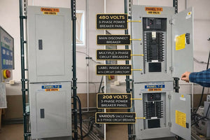
This is where many panelboard mistakes happen. The service disconnect is the point where the neutral bonds to the enclosure. In downstream panels, the neutral must stay isolated from the equipment ground. If you tie them together again, you create parallel neutral-to-ground paths.
Grounding Electrode System Components Used in the Field
NEC 250.50 says all qualifying electrodes at a building must be bonded together into one grounding electrode system. So if a building has a metal underground water pipe, structural steel, a concrete-encased electrode, and ground rods, all of them must be tied together.
Here are the electrode types you’ll most often see on U.S. commercial and industrial jobs:
| Electrode Type | Key NEC Requirement |
|---|---|
| Metal underground water pipe | At least 10 ft of direct contact with earth; electrically continuous or bonded across nonmetallic sections. |
| Metal in-ground support structure (building steel) | At least 10 ft of direct contact with earth. |
| Concrete-encased electrode (Ufer) | Reinforcing steel or bare copper conductor encased in concrete in contact with earth; a highly effective, low-impedance connection. |
| Rod and pipe electrodes | Minimum 8 ft in length; a single rod must be supplemented unless the resistance to earth is 25 Ω or less. |
| Ground ring | Bare conductor that completely encircles the building and is buried in contact with earth; minimum size and burial depth are set by the NEC. |
Tying all present electrodes into one system helps reduce voltage differences across the building. On the job, that usually means bonding the water pipe, building steel, and the service GEC connection together so the grounding system still works even if someone changes the piping later.
Once you know what electrodes are present, the next step is sizing the grounding electrode conductor.
How to Size the Grounding Electrode Conductor Using Table 250.66
NEC Table 250.66 sizes the GEC from the largest ungrounded service-entrance conductor, not from the overcurrent device rating. This trips people up all the time. A common mistake is reaching for Table 250.122, but that table is for equipment grounding conductors, not grounding electrode conductors.
Here’s a plain example: a 200 A single-phase service with 3/0 AWG copper ungrounded conductors needs a 4 AWG copper GEC under Table 250.66.
If the service has parallel conductors per phase, add the cross-sectional areas of all parallel conductors together, then use that total to size the GEC. Think of it as sizing from the full phase conductor area, not from just one conductor in the set.
Sections 250.66(A) through (C) permit a smaller GEC when the connection is only to a rod, pipe, or plate electrode. That smaller size applies only when those are the only electrode types in the system.
Grounding does its job only when bonding provides a continuous fault-current path. That path comes down to bonding, which is up next.
sbb-itb-501186b
Grounding, Service Equipment [250.24, 2020 NEC]
Bonding Basics: Fault-Current Path, Main Bonding Jumper, and Neutral Separation
If grounding stabilizes voltage, bonding is what clears faults.
What an Effective Ground-Fault Current Path Must Do
Grounding ties the system to earth. Bonding completes the path a fault current uses to get back to the source. And that part matters a lot, because earth is not an effective fault-current path. Its impedance is too high to let enough current flow to trip a breaker or blow a fuse.
NEC 250.4(A)(5) says an effective ground-fault current path must be electrically continuous and low impedance. In plain English, if a hot conductor hits a metal enclosure, the fault current has to get back to the source fast enough for the overcurrent device to open.
That return path can run through bonded EGCs, raceways, cable armor, enclosures, and equipment frames. But the chain is only as strong as its weakest link. One loose fitting or one missing bonding jumper can interrupt that path, even if the conductors are sized the right way.
Main Bonding Jumper, System Bonding Jumper, and Supply-Side Bonding Jumper
These three bonding connections set up the fault-current path at different parts of the system. Each one belongs in a specific place.
| Bonding Connection | Where It Goes | What It Does |
|---|---|---|
| Main bonding jumper (MBJ) | Service equipment only | Bonds the grounded conductor to the equipment grounding system at service equipment. |
| System bonding jumper (SBJ) | Separately derived systems - transformer secondaries, generators | Creates the fault path at a separately derived source. |
| Supply-side bonding jumper (SSBJ) | Line side of the service disconnect or supply side of a separately derived system | Bonds metal parts on the supply side of the disconnect. |
At a transformer secondary, the SBJ is the connection that establishes the fault path for that separately derived system.
Why Neutral-to-Ground Connections Are Only Allowed at the Service Disconnect
The neutral carries normal load return current. The equipment grounding path is for fault current only. Mix those jobs by bonding neutral and ground in more than one spot, and neutral current can start flowing on conduit, enclosures, and building steel. That can put current on metal parts, create stray voltage, and increase shock risk.
NEC 250.24 requires the neutral-to-ground bond through the MBJ at the service disconnect. Downstream panelboards have to keep the neutral bar and equipment grounding bar isolated from each other. NEC 250.142(B) also bars the grounded conductor from being used as an equipment grounding conductor on the load side of the service disconnect, except where the Code specifically allows it.
This is a common subpanel mistake. A bonding screw left in place, or any neutral-to-ground tie in a downstream panel, can put stray current where it doesn't belong, trip GFCIs for no good reason, and create a code violation.
With the fault path set, the next step is sizing the equipment grounding conductors that carry fault current.
Equipment Grounding Conductors and Key NEC Sizing Tables
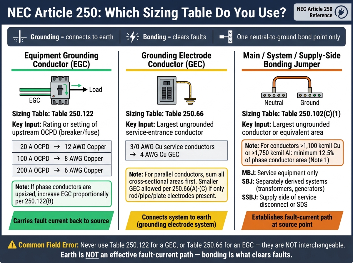
NEC Article 250: GEC vs EGC vs Bonding Jumper Sizing Guide
Once the fault path is set, the next job is sizing the conductors that carry that fault current.
Where Equipment Grounding Conductors Are Required
An equipment grounding conductor (EGC) provides a low-impedance fault-current path that bonds non-current-carrying metal parts back to the source. EGCs run with feeders and branch circuits to panelboards, switchgear, motor controllers, transformers, and other metal-enclosed equipment.
In some cases, an approved metallic raceway can serve as that fault path. But there's a catch: all fittings, couplings, connectors, and enclosures have to stay electrically continuous. If one connection comes loose, the path can fail even if the conductors were sized the right way.
Any exposed metal part that could become energized needs a dependable fault-current path back to the source. That's the whole point of the EGC.
Table 250.122 sizes the conductor that carries fault current. It does not size the conductor that bonds the system to earth.
How to Size Equipment Grounding Conductors Using Table 250.122
Table 250.122 sizes the EGC based on the breaker or fuse rating, not the load current or phase conductor size. That's where a lot of field errors show up.
| OCPD Rating | Minimum EGC - Copper |
|---|---|
| 20 A | 12 AWG |
| 100 A | 8 AWG |
| 200 A | 6 AWG |
So if you have a 100 A feeder protected by a 100 A breaker, you need at least an 8 AWG copper EGC, no matter what the load ends up drawing. A 200 A feeder protected by a 200 A breaker needs at least 6 AWG copper.
There's one adjustment that trips people up. If the ungrounded phase conductors are upsized - for voltage drop, for instance - the EGC also has to be increased in proportion under NEC 250.122(B). That increase is based on the larger conductor area in circular mils. On long feeder runs, skipping that step is a common mistake.
The EGC and the grounding electrode conductor (GEC) do not come from the same table. The GEC connects the system to the grounding electrode system - ground rods, concrete-encased electrodes, and metal water pipe - and it follows different NEC rules. Using Table 250.122 for a GEC is another field error that shows up a lot.
Bonding jumpers follow a different sizing rule too.
How to Use Table 250.102(C)(1) for Bonding Jumpers and Grounded Conductors
Table 250.102(C)(1) sizes the main bonding jumper (MBJ), system bonding jumper (SBJ), supply-side bonding jumper (SSBJ), and certain grounded conductors. Here, the sizing input is the largest ungrounded conductor, or the equivalent conductor area - not the OCPD rating.
On a separately derived transformer secondary, the SBJ is sized from the largest secondary ungrounded conductor or equivalent area.
For conductors larger than 1,100 kcmil copper or 1,750 kcmil aluminum, Note 1 sets a 12.5% minimum.
This table keeps the two sizing paths straight:
| Conductor Type | NEC Table | Key Sizing Input |
|---|---|---|
| Equipment grounding conductor (EGC) | Table 250.122 | Rating or setting of upstream OCPD |
| EGC with upsized phase conductors | NEC 250.122(B) | Circular mil area of upsized conductors |
| MBJ, SBJ, SSBJ, certain grounded conductors | Table 250.102(C)(1) | Largest ungrounded conductor size or equivalent area |
It's easy to mix these up. But using 250.122 for bonding jumpers, or 250.102(C)(1) for EGCs, can leave metal parts under-bonded and slow fault clearing. Those distinctions matter most at services and separately derived systems.
Services, Separately Derived Systems, Common Field Errors, and Final Takeaways
Grounding and Bonding at Service Equipment and Transformers
Once the conductors are sized correctly, the next thing to check is where each one ends up.
At service equipment, the grounded conductor, grounding electrode conductor, and main bonding jumper work together to create one effective fault-current path. The service grounded conductor terminates on the neutral bus. The GEC runs from that bus to the grounding electrode system. And the MBJ connects the neutral bus, equipment grounding bus, and metal enclosure at that single bonding point. That’s also the permitted point where the GEC lands.
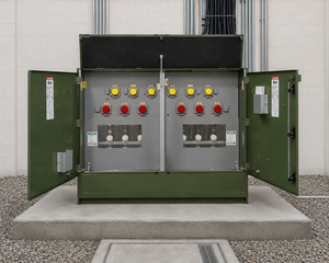
Transformers work off the same basic idea, but the bond point shifts with the separately derived system. If a transformer secondary is an SDS, it needs its own single bonding point under NEC 250.30. The SBJ does for an SDS what the MBJ does for a service. It goes at the transformer or at the first disconnect, not both. A separate GEC also has to run from the derived system to the building grounding electrode system, sized under Table 250.66. After that, the secondary panel is treated like a subpanel, which means the neutral bus stays isolated.
Common NEC Article 250 Mistakes in Commercial and Industrial Work

These are the mistakes that most often wreck the fault-current path in the field.
| Issue | Correct Practice | Incorrect Practice |
|---|---|---|
| Neutral-to-ground bond location | Bond only at the service MBJ or SDS SBJ | Add bonds in subpanels or downstream disconnects |
| Transformer SDS bonding location | Place SBJ at the transformer or first disconnect, not both | Bond at the secondary panel instead of at the transformer or first disconnect |
| Bonding of raceways, piping, and steel | Use listed fittings or bonding jumpers throughout | Rely on set-screws or mechanical joints alone at knockouts not listed for grounding |
Unbonded structural steel and metal piping keep showing up as trouble spots in large facilities. If a fault reaches an unbonded steel column or an isolated pipe section, the current may not have a dependable path back to the source. When that happens, the breaker might not trip fast enough, and metal surfaces can stay energized.
Conclusion: Key Article 250 Points to Check on Every Project
On every project, check three things: the service or SDS bond point, the grounding path, and the correct sizing table for each conductor. That means Table 250.66 for GECs, Table 250.122 for EGCs, and Table 250.102(C)(1) for bonding jumpers.
FAQs
How do I know if a panel is a service panel or a subpanel?
Check for the main bonding jumper. It connects the neutral bar to the metal enclosure. Under the NEC, the neutral-to-ground bond should happen only at the service entrance.
Here’s the key difference:
- In a service panel, neutral and ground are bonded.
- In a subpanel, they must stay isolated, with grounding conductors kept separate from the neutral conductor.
When does a transformer count as a separately derived system?
A transformer is a separately derived system when there is no direct electrical connection between the supply conductors and the output conductors, aside from grounding and bonding.
Put simply, the output circuit gets power from the transformer windings - not from a direct physical connection to the source circuit.
What happens if neutral and ground are bonded in more than one place?
Neutral-to-ground bonds should happen only at the service entrance. If that bond shows up in more than one spot, neutral current can split off and travel along metal enclosures, raceways, and other conductive parts.
That’s where trouble starts. Those metal surfaces can become energized, which adds shock risk. It can also mess with the ground-fault current path that circuit protection devices rely on to trip as they should.