
Best Practices for APFC Panel Selection
If I had to sum this up in one line: I would not choose an APFC panel from nameplate kVAR alone. I would size it from measured load, check harmonics, match the switching gear, verify code and SCCR, and make sure the enclosure can handle heat. That is what keeps power factor near 0.95 to 0.99 without drifting into failure, nuisance trips, or extra utility charges.
In plain terms, here’s what matters most:
- Measure first. Use actual kW, kVAR, THD, and load swings across a full operating cycle.
- Size for the target PF. Many sites aim for about 0.98 lagging, not unity and not leading.
- Pick the right steps. Small first steps and mixed step sizes help stop hunting.
- Treat harmonics early. If the site has VFDs, UPS systems, or rectifiers, a plain capacitor bank may run hot or fail.
- Match the hardware. Capacitor banks need capacitor-duty contactors, proper fuse/breaker sizing, and an SCCR that meets site fault current.
- Check U.S. rules. I would confirm NEC Article 460, UL 508A, IEEE 519, and NFPA 70E before sign-off.
- Do not ignore heat. Many panels use 95°F (35°C) as a base rating, and hotter rooms cut capacitor life.
A few numbers stand out. Capacitor-bank switching can see inrush current up to 75 kA on larger banks. Detuned designs on 480 V / 60 Hz systems often use 525 V or 600 V capacitors. And branch protection is often sized around 1.3 to 1.5 times nominal capacitor current.
APFC Panel Design Types: Standard vs. Detuned vs. Filtered vs. Active Filter
APFC Panel Design With Siemens Power Factor Correction Relay - KVAR Calculation
sbb-itb-501186b
Quick Comparison
| Selection Area | What I Would Check | Why It Matters |
|---|---|---|
| Bank size | Measured load and PF target | Stops under- or over-correction |
| Step layout | Smallest step at about 5% to 10% of total bank | Helps stop hunting |
| Harmonics | THD at the PCC, VFD/UPS presence | Helps avoid resonance and overheating |
| Switching | AC-6b contactors or thyristors | Matches load-change speed |
| Protection | Fuse/breaker size, CT ratio, SCCR | Helps with fault and inrush duty |
| Compliance | NEC, UL 508A, IEEE 519, NFPA 70E | Helps with approval and safe installation |
| Enclosure/cooling | NEMA type, airflow, room temperature | Heat has a direct effect on life |
My takeaway: the right APFC panel is not just the one with the right kVAR number. It is the one that fits the site’s load pattern, harmonic profile, fault level, and room conditions from day one.
Why APFC Panel Selection Goes Beyond Nameplate Sizing
Nameplate kVAR tells you the maximum rated reactive load. It does not tell you what the system pulls during day-to-day operation. That’s the trap.
A better way is to size the panel from measured kW and the actual load profile, then work out how much correction you need to hit the target power factor. Use:
kVAR = kW × (tan φ₁ − tan φ₂)
That matters because the target power factor isn’t just an electrical decision. It’s also a billing decision. Utility penalties, kVARh charges, and peak kVA billing can change the payback in a big way, so they need to be part of the sizing process.
Harmonics also need a hard look. If the site has VFDs, UPS systems, or rectifiers, standard capacitor banks can run hot and fail early. That’s why THD should be checked before you choose the panel. On 480 V / 60 Hz systems, detuned setups often use 525 V or 600 V capacitor ratings.
Temperature is another detail people skip. Standard APFC panels are rated at 95°F (35°C), but many electrical rooms run hotter than that. When they do, thermal aging speeds up and service life drops.
It also helps to think a step ahead. If more load may be added later, leave spare steps or choose extra busbar capacity now rather than boxing yourself in later.
| Selection Factor | What to Measure or Confirm |
|---|---|
| Load profile | Average kW, peak kW, and daily load variation |
| Utility billing | Penalty threshold (e.g., PF < 0.85 or 0.90), kVARh charges, or peak kVA demand |
| Harmonic content | Total Harmonic Distortion (THD) from VFDs, UPS, or rectifiers |
| System voltage | 480 V / 60 Hz; capacitor voltage rating (525 V or 600 V for detuned designs) |
| Ambient temperature | Confirm site temperatures against the 95°F (35°C) design baseline |
| Future growth | Spare slots or a higher busbar rating for planned load additions |
These inputs shape the panel spec. Next, match that spec to the source switchgear and protection.
1. Source Compatible Switchgear and Protection Through Electrical Trader
Once the panel spec is locked in, the next job is simple in theory and easy to get wrong in practice: match that spec to the actual hardware. Electrical Trader brings new and used switchgear, breakers, contactors, and protection gear into one place, which makes it easier to check ratings before you buy.
Start with the contactor. This is where people can slip up. Standard contactors are not capacitor-duty contactors, and they are not interchangeable. Standard contactors are not rated for switching capacitor banks. When banks above 100 kVAR are switched, capacitor banks can produce inrush currents up to 75 kA. That is a heavy hit.
For that reason, capacitor-duty contactors matter. Units rated under the AC-6b utilization category in IEC 60947-4-1 use early-make auxiliary contacts and damping resistors to deal with that switching demand. When you're browsing listings, filter for AC-6b on purpose. Don't assume the part is suitable just because the frame size looks right.
Then check branch protection against the capacitor bank. Size breakers and HRC fuses at 1.3 to 1.5 times nominal capacitor current to allow for tolerance and harmonics. If the site has VFDs or UPS systems, branch current can climb to 1.2 to 1.8 times fundamental current. In plain terms, this is a buying check: confirm the protection size before ordering, not after the gear shows up.
The assembly's SCCR also has to line up with the fault current available at the installation point. Check the SCCR on the nameplate. Common values include 50 kA and 70 kA. Then compare that rating with the facility's prospective fault level from the short-circuit study. Since Electrical Trader includes both new and used equipment, that check matters either way.
After that, move to the control side. Match the CT ratio to the site's maximum demand current, and make sure the relay is set up for a 1 A or 5 A secondary. The CT should be installed on the incoming mains after the utility meter and before the APFC panel connection, so the controller reads net power factor.
2. Choose the Right Total kVAR Rating
Once you've matched the source and protection, the next step is setting the bank's total kVAR based on measured demand.
Start with real data, not a guess. Log kW, kVAR, and THD across a full production cycle before you size the bank. Then use kVAR = kW × (tan φ1 − tan φ2) to turn that measured load into the bank size you need. Make sure the sizing reflects load changes during peak periods, shift schedules, and seasonal swings.
Aim for about 0.98 lagging at the point of common coupling. Many utilities apply penalties when PF drops below 0.95, so it helps to leave some margin and stay on the lagging side. Don’t aim for unity or leading PF. That can push the system into overcorrection.
It also makes sense to round the total kVAR up a bit. A small margin helps cover capacitor aging and near-term load growth.
If the site has VFD, UPS, or rectifier loads, pair the bank with 7% or 14% detuned reactors to help avoid resonance. That total kVAR will then guide the step sizes.
3. Choose Step Sizes That Reflect Load Variability
Once you know your total kVAR target, the next move is deciding how to split that capacity into switching steps. This part matters more than it seems. If the steps are too large or poorly spaced, the bank can start hunting at higher load and drift into a leading power factor when load drops.
A good rule is to set the smallest step at 5% to 10% of the total bank size and keep it below half of the smallest expected load change. For a 300 kVAR panel, that works out to 15 to 30 kVAR. But if your loads move in 20 kVAR increments, the smallest step should be 10 kVAR max.
The largest step should stay at 100 kVAR or less.
It also helps to use mixed step sizes instead of making every stage the same. A setup like 1:1:2:2:4 gives you more correction combinations without adding extra stages. That gives the controller more room to respond without overcorrecting. Step mix and switching method need to fit together.
Switching method should match how fast the load changes:
- Use thyristor switching for fast-changing loads.
- Use capacitor-duty contactors for steadier loads.
- Set a 60-second discharge delay before re-energizing any step.
If loads swing fast and the switching gear lags behind, even a well-sized bank can behave poorly. That’s why step sizing and switching type need to be planned as a pair, not as separate choices.
4. Address Harmonics With Detuned or Filtered Designs
Once you've sized the kVAR and picked the step mix, check harmonic behavior before you lock in the panel design.
This matters a lot when the system includes non-linear loads like VFDs, UPS systems, rectifiers, or welders. In those cases, detuned reactors should usually be the default pick because they help limit resonance and reduce harmonic stress. A standard capacitor bank can increase harmonic current. And if the resonant frequency lines up with a dominant harmonic, you can end up with equipment damage and a shorter capacitor life.
Use series detuned reactors to move the LC resonant frequency below the lowest major harmonic. Common detuning levels are 7% and 14%, selected based on the harmonic spectrum and system impedance. One catch: detuning increases capacitor voltage. So on a 480 V system, specify 525 V or 600 V capacitors.
Detuned reactors also add continuous heat. That means the panel needs proper cooling from the start. Specify ventilation, filtered fans, or air conditioning, and include reactor temperature monitoring for alarm or trip protection.
Use detuned banks when voltage THD at the PCC is above 5%. It's smart to run a harmonic survey early in the design phase and measure both THD_V and THD_I at the PCC before sizing the panel. That call affects component ratings and enclosure cooling, so harmonics shouldn't be treated like a last-minute extra.
Sometimes the harmonic profile shifts with operating mode. In that case, fixed detuning by itself may not do the job. When the harmonic spectrum varies, an Active Harmonic Filter may be the better fit. It can also work alongside detuned capacitors, with the capacitors handling fundamental reactive power and the filter dealing with dynamic distortion.
5. Confirm Compliance With U.S. Codes and Product Standards
Once the electrical design is set, check the codes and standards that control installation and listing. This step is part of APFC panel selection. It affects safety, inspection approval, and product listing.
Use NEC Article 460 for capacitor installation and protection. Use NEC Article 110 for working clearances. Also check for discharge resistors so residual voltage drops after shutdown.
For the panel assembly, use UL 508A. If the panel is going into machinery, NFPA 79 also applies.
Use IEEE 519 to benchmark distortion at the PCC. And when sizing current-carrying parts, base that work on actual RMS current, not just fundamental current. That turns the harmonic survey into a compliance check, not just a design note.
You’ll also want to verify that the panel SCCR meets or exceeds the prospective fault current at the installation point. The nameplate should state that rating clearly.
Use this checklist before purchase:
| Standard/Code | Focus Area |
|---|---|
| NEC Article 460 | Capacitor installation, protection, and discharge requirements |
| NEC Article 110 | General installation requirements and working clearances |
| UL 508A | Industrial control panel safety |
| IEEE 519 | Harmonic distortion control at the PCC |
| NFPA 79 | Electrical machinery applications |
6. Match the Enclosure and Cooling Design to the Installation Site
The enclosure has a direct effect on capacitor life and thermal stability. Pick the wrong one, and you shorten equipment life and invite more downtime.
Once the electrical design is locked in, the next heat-related choice is the enclosure. A clean electrical room usually fits NEMA 1 or NEMA 12 (IP20 to IP54). A dusty manufacturing area needs NEMA 12 (IP54+) with filtered ventilation. For outdoor or exposed locations, use NEMA 3R, 4, or 4X based on how much weather and washdown exposure the panel will face.
Capacitors and detuned reactors give off heat all the time. Use 95°F (35°C) as the thermal baseline. If the site runs hotter than that, derate the panel or add forced cooling.
Then there’s the inside of the panel. That part matters more than people sometimes expect. Step count, partitions, ventilation paths, and protective devices all affect heat rise. For detuned designs, layout matters just as much as cooling capacity. Place detuned reactors where vertical airflow can move freely, and keep them away from control electronics. In harmonic-heavy sites, add temperature sensors with alarm contacts tied to SCADA or a PLC so the team can track thermal rise over time before it turns into a failure.
| Installation Site | Enclosure Rating | Cooling Method |
|---|---|---|
| Indoor electrical room | NEMA 1 or 12 | Natural ventilation for small banks; filtered fans for larger units |
| Dusty manufacturing area | NEMA 12 (IP54+) | Filtered ventilation; regular filter maintenance required |
| Outdoor or exposed sites | NEMA 3R, 4, or 4X | Sun shields; thermostatic cooling and heating for ambient extremes |
| Detuned or high-harmonic sites | Standard or heavy-duty | Forced cooling (fans or AC) due to reactor heat |
7. Focus on Component Quality, Controls, and Long-Term Value
Once you've checked sizing, harmonics, and enclosure fit, component quality becomes the thing that shapes service life.
Capacitors have the biggest effect on life-cycle cost. They do most of the heavy lifting, so weak capacitor specs can come back to bite you. Specify capacitors that comply with IEC 60831-1/2 and carry a rating of at least 1.1 times system voltage.
Switching devices are the next big call. Standard contactors tend to wear out fast in capacitor-switching duty. For stable loads, use AC-6b capacitor-duty contactors. For loads that change fast, such as welders and cranes, use thyristor switching.
The APFC controller also plays a big part in correction accuracy and component wear. Intelligent microprocessor-based controllers use switching logic that spreads switching cycles across all capacitor steps, instead of overworking one bank while the others sit idle. That even distribution helps avoid early wear on a single step. These controllers should also support mixed-step logic for finer correction. In practice, it's smart to give extra weight to controllers with:
- LCD displays
- Logging
- Modbus RTU/RS-485 support
Before you lock in the design, verify fuse coordination. HRC fuses (NH type) clear faults fast for capacitor protection and can limit damage to the rest of the assembly.
Better parts usually mean lower total cost over time. Fewer penalties, less heat loss, and fewer replacements all add up. Use the comparison tables below to weigh these part-level trade-offs.
Comparison Tables to Support Your Decision
Use the tables below for a quick side-by-side look at step mix, harmonic design, and placement.
Capacitor Step Size Arrangements
For variable loads, the smallest step should be about 5% to 10% of the total bank size to help prevent hunting.
| Arrangement | Control Accuracy | Switching Frequency | Space Used | Total Installed Cost |
|---|---|---|---|---|
| Equal Steps (1:1:1) | Moderate | High | Large | Higher |
| Mixed (1:2:2:4) | High | Moderate | Compact | Lower |
| Single Fixed Bank | Low | Low | Smallest | Lowest |
Step mix is just one piece of the choice. Harmonics matter too, because they often decide whether a standard, detuned, or filtered design makes more sense.
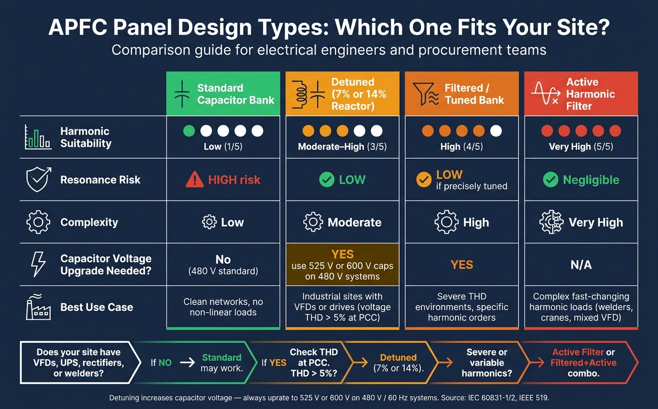
Standard vs. Detuned vs. Filtered APFC Designs
Standard banks work best on clean networks. Detuned or filtered options are a better fit for sites with heavier harmonic content.
| Design Type | Harmonic Suitability | Resonance Risk | Complexity | Best Use Case |
|---|---|---|---|---|
| Standard | Low | High | Low | Clean networks with no non-linear loads |
| Detuned (7%) | Moderate to High | Low | Moderate | Industrial sites with VFDs or drives |
| Filtered/Tuned | High (specific orders) | Low if precisely tuned | High | Severe THD environments |
| Active Filter | Very High | Negligible | Very High | Complex, fast-changing harmonic loads |
If the system has drives, VFDs, or other non-linear loads, this table usually narrows the field fast. A standard bank may look cheaper up front, but the wrong harmonic fit can cause trouble.
Centralized vs. Distributed APFC Placement
Use this table to line up APFC placement with the site goal: cutting utility penalties or cutting internal losses.
| Feature | Centralized (Main Bus) | Distributed (At the Load) |
|---|---|---|
| Installation Cost | Lower | Higher |
| Flexibility | Low | High |
| Maintenance Effort | Low | High |
| Primary Benefit | Reduces utility penalties | Reduces internal cable and transformer losses |
A centralized setup at the main bus is often the simpler path when the main target is utility bill correction. A distributed setup, by contrast, can trim cable and transformer losses closer to where the reactive power is being used.
After you narrow down the layout, verify the final panel against U.S. codes and product standards.
Key U.S. Standards and Design Checks to Review
Use this final checklist to verify the panel before purchase. Before you buy an APFC panel, make sure it meets U.S. code rules, harmonic limits, and fault-current requirements.
Start with IEEE 519. It’s the go-to standard for checking distortion limits at the PCC. If the site uses VFDs, rectifiers, or UPS systems, compare measured THD with IEEE 519 limits before you approve the design. That step matters because harmonics can quietly create trouble if the panel isn’t built for them.
Next, check the SCCR against the available fault current. This is one of the most important nameplate items to review. The declared SCCR must meet or exceed the prospective fault current at the installation point. Also verify that each capacitor step has coordinated overcurrent protection, not just the panel as a whole.
Before sign-off, confirm these installation-ready items:
- Discharge resistors are installed on every capacitor unit
- The controller includes a discharge time delay before re-energizing any step
- Internal conductors and busbars are sized for harmonic RMS loading
- NFPA 70E arc flash and shock protection requirements are applied
- Warning labels showing stored energy and discharge times are in place
This gives you a practical last-pass check before installation approval.
| Compliance Check | Relevant U.S. Standard | Key Requirement |
|---|---|---|
| Capacitor Installation | NEC Art. 460 | Overcurrent protection and discharge of stored charge |
| Working Clearances | NEC Art. 110 | Minimum clearances and equipment mounting |
| Harmonic Distortion | IEEE 519 | Current and voltage distortion limits at the PCC |
| Short-Circuit Rating | SCCR Nameplate Marking | Must exceed prospective fault current at the installation point |
| Worker Safety | NFPA 70E | Worker protection during maintenance |
Conclusion
APFC selection comes down to seven connected calls. Size the panel from measured load, match step sizes to how the load moves, check harmonics, verify compliance, fit the enclosure to the site, and put component quality near the top of the list. In the U.S., that also means confirming UL 508A, NEC Article 460, and SCCR ratings.
Purchase price is only part of the picture. A panel that skips harmonic protection or comes without verified thermal performance may look cheaper at first, but it can end up costing far more in downtime, failures, and replacement parts. The right APFC panel is the one that runs well over time, protects the electrical system, and cuts total cost in the long run.
FAQs
How do I know if my facility needs a detuned APFC panel?
Consider a detuned APFC panel if your facility runs non-linear loads like VFDs, welding machines, or UPS systems. These loads can add harmonic distortion to the system, which may lead to resonance and, in some cases, damage a standard capacitor bank.
A detuned panel uses reactors to help shield capacitors from overheating and resonance. If you're not sure whether this setup is needed, a power quality audit or harmonic analysis can give you a clear answer.
What power factor target should I aim for?
Aim for a power factor between 0.95 and 0.99. In most cases, getting close to unity gives you the best mix of efficiency and lower risk of utility penalties.
That said, the right target isn’t the same for every site. It also depends on your utility’s rules and your facility’s harmonic conditions.
Don’t set the target too high. If you overcorrect, you can end up with a leading power factor, voltage spikes, and extra penalties.
When should I choose thyristor switching over contactors?
Choose thyristor switching when your facility has changing or dynamic loads, like welding equipment or elevators.
It reacts almost instantly, supports zero-current switching to cut transients and voltage spikes, and avoids the wear that comes with mechanical parts. Contactors usually make more sense for steady loads because they cost less. Thyristor modules are a better fit when load demand changes often.


