




How APFC Panels Save Energy Costs
Automatic Power Factor Correction (APFC) panels can help businesses cut energy costs by improving power factor and reducing utility penalties. Here's what you need to know:
- What They Do: APFC panels automatically adjust capacitor banks to maintain an optimal power factor, reducing reactive power and wasted energy.
- Why It Matters: Low power factor leads to higher electricity bills, utility penalties, and equipment wear. Facilities with a power factor below 0.85–0.95 often face penalties ranging from $2,000 to $50,000 annually.
- Savings Potential: Correcting power factor can lower energy costs, reduce heat-related wear on equipment, and free up capacity for future growth. Most installations pay for themselves in 2–4 years.
- Key Benefits: Improved equipment lifespan, reduced heat losses, and elimination of utility surcharges. For example, increasing power factor from 0.8 to 0.95 can boost transformer capacity by nearly 20%.
APFC panels are a practical solution for businesses looking to reduce energy expenses while maintaining system efficiency. Below, we dive into how they work, their benefits, and how to choose the right system for your facility.
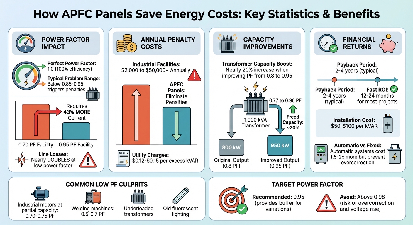
APFC Panel Energy Savings and ROI Statistics
Power Factor and Its Effect on Energy Costs
What Is Power Factor?
Power factor (PF) measures how efficiently your system uses power, calculated as kW divided by kVA. In simpler terms, it compares the energy used to power equipment (real power) to the total power supplied (apparent power).
A perfect power factor of 1.0 (or 100%) means all the current in your system is doing useful work. Anything below 1.0 indicates the presence of reactive power, which doesn’t perform any productive work but is needed to sustain magnetic fields in inductive equipment like motors and transformers. The formula for calculating power factor is straightforward: PF = Active Power (kW) / Apparent Power (kVA). When power factor drops, inefficiency creeps in, leading to operational challenges and higher costs.
Problems Caused by Low Power Factor
Low power factor isn’t just a technical issue - it directly impacts energy costs and equipment performance. When the power factor is low, your facility pulls more current than necessary to perform the same amount of work. For example, a facility operating at 0.70 power factor requires 43% more current than one at 0.95, which nearly doubles line losses. This extra current generates heat in cables, transformers, and switchgear, wasting energy and shortening equipment life.
The financial impact can be steep. Utilities often penalize facilities with power factors below 0.85–0.95. These penalties appear on energy bills under terms like "kVAR Charge", "Adjusted Demand Charge", or "Power Factor Penalty". For industrial facilities, these penalties can range from $2,000 to over $50,000 annually. Some utilities charge $0.12–$0.15 per excess kVAR, while others increase the entire demand charge based on how far the power factor falls below their threshold.
The primary culprits behind low power factors are inductive loads. Industrial induction motors running at partial capacity often operate with power factors as low as 0.70–0.75. Welding machines are even worse, frequently running between 0.5 and 0.7 power factor. Other contributors include underloaded transformers and older fluorescent lighting systems with magnetic ballasts.
sbb-itb-501186b
How APFC Panels Correct Power Factor
Continuous Power Factor Monitoring
APFC panels tackle the inefficiencies of a low power factor by constantly monitoring system performance. Using sensors and current transformers (CTs), these panels measure voltage and current levels. A microprocessor then calculates the power factor by comparing active power to apparent power, ensuring it meets a set threshold (commonly 0.95 or 0.99). If the power factor dips below this level - often due to inductive loads - the controller activates switching mechanisms to engage capacitor stages. These adjustments, made in real-time, ensure the system adds or removes capacitors as energy demands fluctuate .
Automatic Capacitor Switching
To maintain the target power factor, APFC panels use magnetic contactors or thyristors to precisely manage the switching of capacitor circuits. This staged approach ensures only the required amount of capacitance is deployed, avoiding unnecessary corrections. When energy demands decrease, the system disconnects excess capacitor stages to prevent overcorrection. By supplying reactive energy locally through these capacitor banks, the panel keeps the power factor steady during both high-demand and low-demand periods .
Reducing Reactive Power Losses
APFC panels help reduce reactive power losses by supplying reactive energy locally, which lowers the overall current in the system. This reduction minimizes I²R losses in wiring and transformers. With less current flow, heat generation in cables and switchgear decreases, extending the lifespan of cable insulation and delaying the need for costly infrastructure upgrades .
"More current through the installation means higher losses due to the impedance (resistance) of the installation. We also call this the watt losses." - fortop UK
For example, improving the power factor from 0.8 to 0.95 can boost a transformer's usable capacity by nearly 20%, eliminating the need for hardware upgrades. Advanced APFC panels may also feature detuning reactors to shield capacitors from resonance in systems with high harmonic distortion. This added protection reduces heat and eddy current losses in transformers, leading to better energy efficiency and enhanced system performance .
Calculating Energy Savings from APFC Panels
Metrics for Measuring Savings
APFC panels improve energy efficiency by correcting the power factor (PF), and the savings can be measured using specific metrics. One key area to monitor is the reduction in apparent power drawn from the grid, which helps avoid utility surcharges and lowers demand charges. Most utility companies impose penalties when the power factor falls below thresholds like 0.85 to 0.95.
To determine the reactive power (kVAR) management needed, you can use the formula:
kVAR = kW × (tan θ₁ − tan θ₂)
This calculation helps identify the required capacitance to reach your target power factor. To track savings, review your utility bills for charges labeled as "Reactive Power Charges" or "Low Power Factor Surcharges", which reflect penalties that can be avoided with improved power factor correction.
"The biggest mistake I see is facilities accepting utility penalty charges without verification. I've audited hundreds of utility bills and found calculation errors in approximately 15% of cases." - Sarah Martinez, P.E., Licensed Electrical Engineer
Expected Energy Savings
Power factor penalties can add up fast, costing industrial facilities anywhere from $2,000 to over $50,000 annually, depending on their size and energy consumption patterns. For example, a facility operating at a power factor of 0.70 uses 43% more current than one at 0.95, nearly doubling its line losses. Correcting the power factor from 0.77 to 0.96 can free up about 20% more capacity, enabling the facility to handle additional loads without upgrading transformers.
Most power factor correction projects pay for themselves within 12 to 24 months. Installation costs typically range between $50 and $100 per kVAR. While automatic switched capacitor banks cost 1.5 to 2 times more than fixed installations, they prevent over-correction during periods of low load, offering better long-term efficiency. Additionally, utility rates tend to rise by 3% to 5% annually, which amplifies the financial benefits of power factor correction over time.
These metrics provide a solid foundation for evaluating the performance improvements achieved with APFC panels.
Before and After Performance Comparison
To measure the impact of APFC panel installation, start by establishing a baseline. Analyze 12 months of utility data to account for seasonal variations and peak demand fluctuations. Pay close attention to peak demand periods since many utilities calculate penalties based on the peak power factor rather than the monthly average. For instance, a facility might have an average PF of 0.88 but experience a peak PF of 0.72, which could trigger steep penalties.
After installing the APFC panel, compare your updated utility bills with onsite measurements to verify the improved power factor. This step is crucial, especially since calculation errors occur in about 15% of utility bills. Aim for a power factor of 0.95 or higher to maintain a buffer against occasional dips. Document the reductions in current draw, apparent power, and penalty charges to create a comprehensive view of your energy savings. This data illustrates the tangible benefits and long-term value of using APFC panels.
Installing and Optimizing APFC Panels
Evaluating Your Electrical Load Profile
To understand your facility's electrical behavior, install a power quality meter for one to two weeks. This will help you capture both peak and average power factor values under a variety of conditions, such as shift changes, weekend operations, and seasonal load variations.
Key data to focus on includes:
- Power factor during different operating conditions
- Maximum reactive power demand (kVAR)
- Load variation patterns
- Harmonic content
One critical point: prioritize peak demand load rather than average load. Capacitors must be sized for these peak periods, as that's when utility penalties are calculated.
"The most common mistake I see is engineers sizing capacitors based on average load instead of peak demand... The result is undercorrection at peak hours - exactly when penalties are calculated." - Sarah Martinez, P.E., Licensed Electrical Engineer
If your facility's load varies by more than 20%, an automatic APFC panel is a must. Fixed capacitor banks may lead to overcorrection during light load periods. Additionally, conduct a harmonic study. If Total Harmonic Distortion (THD) exceeds 5%, you'll need detuned capacitor banks with series reactors. While these cost 20–30% more than standard capacitors, they help prevent equipment failures in high-THD environments.
These measurements will guide you in selecting an APFC panel that matches your facility's unique load profile.
Selecting the Right APFC Panel
Start by calculating the required kVAR, then round up to the nearest standard capacitor size (e.g., 50, 75, or 100 kVAR). Aim for a power factor of 0.95 - this provides a buffer for load variations without risking overcorrection. Correcting beyond 0.98 lagging can lead to a leading power factor, which may cause voltage rise issues.
Choose between fixed and automatic capacitor banks based on your load's characteristics:
- Fixed banks: Suitable for constant loads with a ±10% variation.
- Automatic APFC panels: Necessary for variable loads with over 20% variation. Though these cost 1.5–2 times more, they prevent overcorrection during low load periods.
For facilities exceeding 1,000 kW or with long feeder runs, distributed correction at load centers is better than centralized correction at the main service. This reduces internal line losses. Look for panels with high-quality microprocessor controllers for real-time monitoring, durable contactors, and proper cooling systems.
System Integration and Testing
Once you've selected the right panel, proper installation and testing are key to ensuring it performs reliably.
Make sure the installation complies with NEC Article 460 and NFPA 70E. Keep voltage rise under 3% to protect equipment. Use a power quality analyzer to measure the improved power factor at both the service entrance and major distribution panels.
Calibrate the controller carefully to avoid a leading power factor, which can cause voltage spikes and equipment damage. Compare the updated utility bills to onsite measurements to confirm the system is working as intended. Regular inspections are essential - check for bulging capacitors and ensure cooling fans are operational to prevent overheating.
For setups with variable frequency drives (VFDs) or UPS systems, always perform a harmonic analysis before finalizing installation. If THD exceeds 5%, standard capacitors won't suffice. You'll need detuning reactors or active PFC systems to handle harmonic-heavy environments.
How APFC Panels Can Slash Your Electricity Bills!
Conclusion: Long-Term Benefits of APFC Panels
APFC panels offer financial benefits that last well beyond the initial investment. The typical payback period ranges from 2 to 4 years, primarily due to the elimination of utility penalties for low power factor. This immediate cost savings is complemented by improved system efficiency, making the panels a practical choice for long-term energy management.
Additionally, APFC panels enhance infrastructure capacity. For example, they can increase the output of a 1,000 kVA transformer from 800 kW to 950 kW, enabling facility expansion without expensive upgrades. This extra capacity supports operational growth, such as adding production lines or new equipment, while maintaining reliability.
By reducing reactive current, APFC panels decrease thermal stress on transformers and cables, extending their lifespan and preventing premature insulation failures. Improved voltage stability also reduces disruptions to automated machinery, ensuring smoother operations. Unlike fixed capacitor banks, which can overcorrect during light load conditions, APFC panels dynamically adjust to changing demands, protecting sensitive electronics from voltage spikes.
Maintenance requirements for APFC panels are minimal. Regular checks should include inspecting capacitors for bulging, ensuring cooling fans are functioning, and verifying controller calibration. For facilities with non-linear loads like variable frequency drives, conducting a harmonic analysis (as outlined in IEEE 519-2022) during installation is essential to avoid resonance issues. This straightforward upkeep reinforces APFC panels as a reliable, long-term solution.
Investing in APFC technology can lead to lower utility expenses, deferred capital investments, and improved system reliability. For businesses focused on reducing energy costs while maintaining operational efficiency, APFC panels are one of the most economical upgrades available.
For expert guidance and premium APFC panels, visit Electrical Trader (https://electricaltrader.com).
FAQs
Do APFC panels reduce kWh usage or mainly demand and penalty charges?
APFC panels play a key role in cutting down demand charges and penalty costs by boosting the power factor. Beyond that, they help trim energy usage and minimize power losses, which leads to better efficiency and noticeable cost savings.
How do I know if my facility needs detuned reactors for harmonics?
If you're wondering whether your facility might need detuned reactors, start by evaluating whether harmonic distortion is impacting your electrical system. Harmonics are often generated by nonlinear loads, such as variable frequency drives, computers, or other modern equipment. These distortions can result in overheating, reduced efficiency, and even equipment malfunctions.
The first step is to perform a harmonic analysis to measure distortion levels. If the results show that the levels exceed acceptable limits or are causing noticeable issues, detuned reactors can be a practical solution. They help reduce resonance and enhance overall power quality.
Where should an APFC panel be installed - main service or near big loads?
An APFC panel works best when installed close to the main switchgear or main service. Placing it here ensures it can efficiently monitor and adjust the power factor across the entire electrical system, which is particularly useful in settings where loads frequently change.





