How to Ground Transformers per NEC Standards
If I want an NEC-compliant transformer grounding setup, I need to get 3 things right: one bond point, proper conductor sizing, and neutral isolation downstream.
Here’s the short answer: when a transformer secondary is a separately derived system, I treat it under NEC 250.30. I bond the neutral to ground at one location only - either at the transformer or at the first secondary disconnect - then size the GEC, system bonding jumper, and EGC from the NEC tables, and make sure the neutral is isolated everywhere else. If I miss any one of those steps, fault current may not return on the path intended, and inspection issues can follow.
What I check first:
- Is the secondary a separately derived system (SDS)?
- Does the system need to be grounded under 250.20, or can it stay ungrounded under 250.21?
- Where is the single neutral-to-ground bond?
- Are the conductors sized by the right NEC sections?
- Are downstream neutral bars isolated from the enclosure?
- Is the grounding electrode tied into the building grounding electrode system, not left on a stand-alone rod?
The main NEC sections covered are 250.20, 250.21, 250.30(A), 250.66, 250.102(C)(1), and 250.122.
A few fast facts help frame the job:
- A 208Y/120V, 4-wire wye secondary will often require grounding.
- An EGC is sized from 250.122 based on the feeder OCPD, such as a 400 A breaker.
- If conductors are over 1,100 kcmil copper or 1,750 kcmil aluminum, the bonding jumper must be at least 12.5% of the largest phase conductor area.
Quick comparison
| Item | What I use it for | How I size or place it |
|---|---|---|
| Grounded conductor (neutral) | Grounded system conductor, often at X0 | Kept isolated downstream if bond is upstream |
| System bonding jumper | Connects neutral to metal parts and grounding path at the single bond point | Sized per 250.102(C)(1) |
| Grounding electrode conductor | Connects the SDS bond point to the grounding electrode system | Sized per 250.66 |
| Equipment grounding conductor | Carries fault current back to the source on the secondary side | Sized per 250.122 |
In plain terms, this article shows me how to tell if the transformer secondary is an SDS, where the bond can go, how to size each conductor, how indoor and outdoor installs differ, and which mistakes most often cause a failed inspection.
Grounding, Transformers [250.30, 2020 NEC]
NEC Rules That Control Transformer Grounding
Once you’ve confirmed the secondary is an SDS, the next step is simple: follow the NEC rules that set the bond point, conductor sizing, and neutral isolation. For transformer secondaries, that means looking at Article 250. The key sections here are 250.20, 250.21, 250.30(A), 250.66, 250.102(C)(1), and 250.122.
Section 250.20 identifies AC systems that must be grounded. That includes common 208Y/120V, 4-wire wye secondaries. Section 250.21 covers cases where a system is allowed to remain ungrounded. That usually applies when continuity of service matters and ground-fault detection is in place.
For transformer secondaries that qualify as separately derived systems, 250.30(A) controls the grounding and bonding arrangement. It helps to keep a few terms straight first.
These are the four conductors and connection points that control transformer grounding.
| Term | What It Does |
|---|---|
| Grounded conductor (neutral) | The conductor intentionally connected to ground - usually X0 on a wye secondary |
| System bonding jumper (SBJ) | Ties the neutral to the EGCs and grounding electrode system at the single permitted bonding point |
| Equipment grounding conductor (EGC) | Connects metal enclosures and equipment frames back to the source to clear faults |
| Grounding electrode system | The building or structure's collection of electrodes used to connect the system to earth |
Where the Neutral-to-Ground Bond Is Permitted
For an SDS, the neutral-to-ground bond is permitted at one point only: the transformer or the first secondary disconnect. If you bond at both, you create parallel paths for neutral current on equipment grounding conductors and metal raceways. That leads to objectionable current and parallel paths.
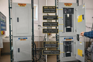
If the bond is made at the transformer, the downstream panel must have an isolated neutral bar. In plain English, that means no bonding screw or strap tying the neutral bar to the equipment ground bar. If the bond is made at the first disconnect instead, the transformer neutral must stay insulated all the way to that panel. Check that neutral isolation before energizing.
How to Size the GEC, EGC, and Bonding Jumper
Once the bond point is set, size the conductors from the secondary side.
- GEC: Size it with Table 250.66, based on the largest ungrounded secondary conductor.
- System bonding jumper and grounded conductor: Size them per Table 250.102(C)(1), based on the largest ungrounded phase conductor. If the conductors are larger than 1,100 kcmil copper or 1,750 kcmil aluminum, the bonding jumper must be at least 12.5% of the cross-sectional area of the largest phase conductor.
- EGC: Size it per 250.122, based on the rating of the overcurrent protective device protecting the secondary circuit. So if a 400 A breaker protects the secondary feeder, the minimum EGC size comes from the 250.122 table entry for 400 A.
Use those sizes when you install the grounding path in the next step.
Step-by-Step: How to Ground a Transformer per NEC
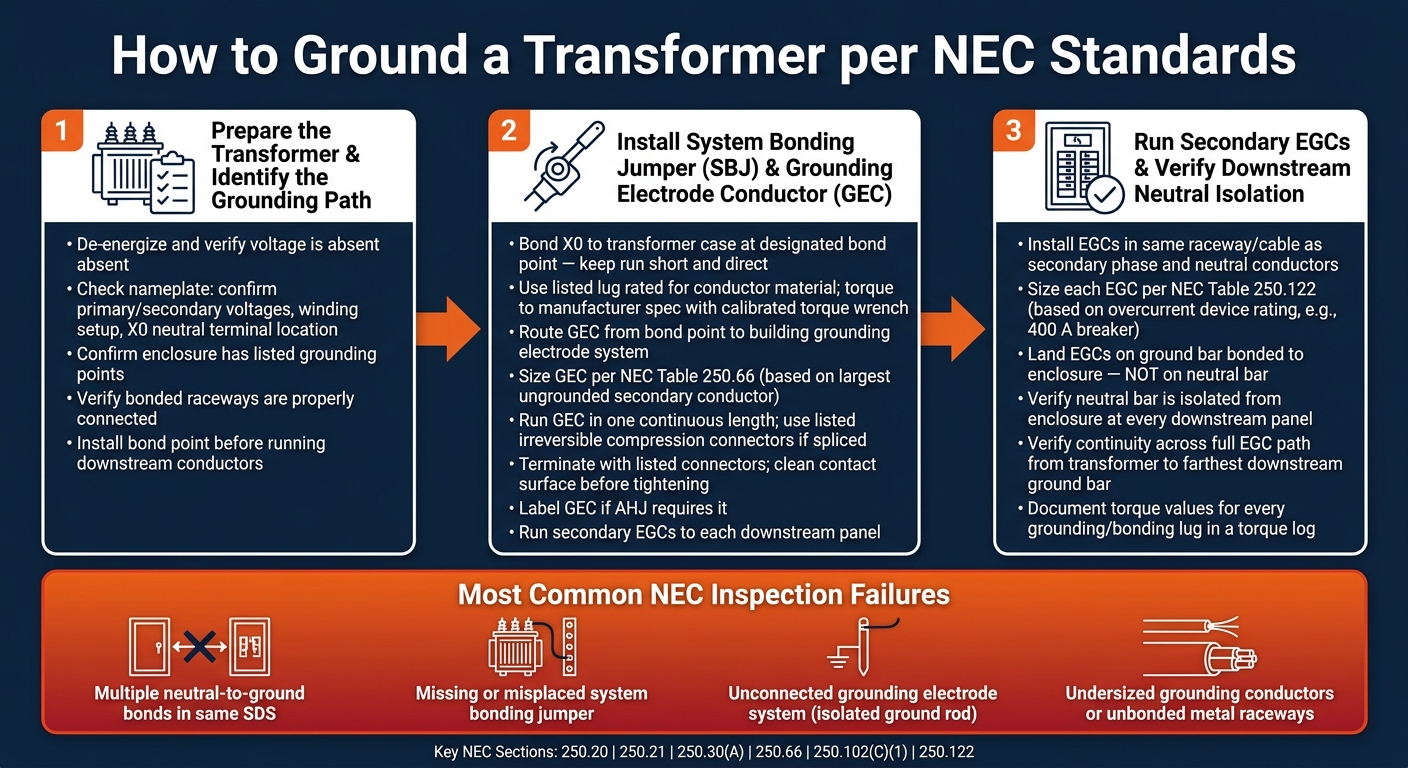
NEC Transformer Grounding: 3-Step Installation Process
Once you’ve nailed down conductor sizes and bond points, the job comes down to three steps. They need to happen in order. If you skip one, it’s easy to end up with bonding mistakes or neutral isolation problems.
Step 1: Prepare the Transformer and Identify the Grounding Path
Start by de-energizing the transformer and verifying that voltage is absent before touching anything. Then identify the equipment grounding path before making any terminations.
Check the nameplate and the manufacturer manual. Confirm the primary and secondary voltages, the winding setup, and the location of the X0 neutral terminal.
Next, make sure the enclosure has listed grounding points and that any bonded raceways are connected the way they should be. Once you’ve confirmed the equipment grounding path, install the bond point before you run any downstream conductors.
Step 2: Install the System Bonding Jumper and Grounding Electrode Conductor
Bond X0 to the transformer case at the designated bond point. Keep that run short and direct. Use a listed lug rated for the conductor material, and tighten the connection to the manufacturer’s specified torque with a calibrated torque wrench.
After the SBJ is installed, route the GEC from that same bond point to the building grounding electrode system. Size it per Table 250.66 based on the largest ungrounded secondary conductor. Run it in one continuous length unless you’re using listed irreversible compression connectors, and terminate it to the grounding electrode system with listed connectors. Clean the contact surface before tightening, and label the GEC if the AHJ requires it.
Once the bond and GEC are set, run the secondary EGCs to each downstream panel.
Step 3: Run Secondary EGCs and Verify Downstream Neutral Isolation
Install EGCs in the same raceway or cable as the secondary phase and neutral conductors going to each downstream panelboard or piece of equipment. Size each EGC per Table 250.122 based on the overcurrent device protecting that feeder.
At downstream panels, land the EGCs on the ground bar bonded to the enclosure, not on the neutral bar. Then check that the neutral bar is isolated from the enclosure. After that, verify continuity across the full EGC path from the transformer enclosure to the farthest downstream ground bar.
Document the torque values for every grounding and bonding lug in a torque log. Record all torque values.
sbb-itb-501186b
Installation Variations, Common Mistakes, and Material Planning
How Outdoor and Oil-Filled Transformer Grounding Differs
Once the bond point and conductor sizes are set, the rest comes down to the transformer type and where it sits. The NEC grounding rules do not change. What changes is the hardware you use and how you route it.
For dry-type indoor transformers, grounding and bonding terminations usually land on one internal ground bar when separate EGCs and supply-side bonding jumpers are installed. That bar must be bonded to the metal enclosure under 250.12, and it can't be mounted over vented parts of the enclosure.
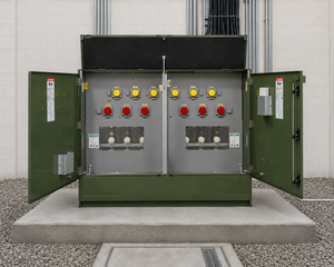
Outdoor equipment brings extra work. Pad-mounted and oil-filled transformers often need tank bonding, arrester grounding, and site grounding connections based on utility standards and local design rules. Pole-mounted transformers follow utility grounding rules too, especially for the neutral grounding path, arrester leads, and bonding of the case and mounting hardware.
For any outdoor setup, use corrosion-resistant lugs and hardware. Sun, rain, and temperature swings wear down exposed connections much faster than indoor terminations.
The trouble usually starts when the secondary gets tied into equipment farther downstream.
Common NEC Grounding Errors on Transformer Secondaries
Most inspection failures on transformer secondaries show up in the same four areas:
- Multiple neutral-to-ground bonds in the same SDS, usually at a downstream panel or ATS cabinet
- Missing or misplaced system bonding jumper, which leaves the secondary without a fault path that can clear the problem
- Unconnected grounding electrode system, which creates an isolated ground rod and breaks Article 250's interconnection rule
- Undersized grounding conductors or unbonded metal raceways, which can push fault current onto paths that may not trip the overcurrent device
Tools and Components to Have Before Installation
Before work starts, stage the parts that match the bond point and conductor sizes you've already chosen. If the right lug, tool, or connector is missing, the crew ends up stopping, changing course, and doing part of the job twice.
At a minimum, have these on-site:
- a torque wrench
- a continuity or low-resistance tester
- conductor strippers
- an approved crimping tool
For listed terminations, check that each lug is rated for the conductor material and conductor size under NEC 250.8. Do not use improvised clamps or non-listed hardware.
It also helps to pre-stage grounding bars, bonding bushings, bonding jumpers, compression connectors, and grounding conductors in the needed AWG sizes. On outdoor jobs or larger systems, bring cable cutters, hole saws or knockout tools, drilling equipment, ground rods, and exothermic weld kits or approved clamps.
Keep the one-line diagram and the manufacturer's installation instructions on-site. That way, the crew can check the full grounding path before energizing.
Conclusion: Key Steps for NEC-Compliant Transformer Grounding
Transformer grounding follows a set sequence. First, confirm how the secondary is grounded, because that choice sets the bond point and the conductor path. Once that's clear, the rest comes down to three things: one bond point, correct conductor sizing, and checked neutral isolation.
Use one neutral-to-ground bond only. Size the GEC, SBJ, and EGCs per NEC tables, and keep all downstream neutral buses isolated from their enclosures. One small miss can trip up an otherwise correct install. A factory bonding screw left in a load-side panel is a common reason a job fails inspection.
Before energizing, verify that the neutral-to-ground bond exists only at the designated point and that the grounding path is continuous. That last check catches the inspection issues that show up most often. The one-line diagram, panel labels, and field installation also need to match so no second bond or open grounding path slips in.
For retrofits and upgrades, Electrical Trader offers new and used electrical components and power distribution equipment.
FAQs
How do I know if my transformer secondary is an SDS?
A transformer secondary is a separately derived system (SDS) when it has no direct electrical connection to conductors from another system. That includes a solidly connected grounded circuit conductor.
Put simply, the secondary is isolated from the primary. Because of that isolation, the secondary terminals become a new power source.
Grounding for that secondary has to follow NEC Article 250.
Should I bond at the transformer or first disconnect?
The neutral-to-ground bond should usually be made only at the service entrance. If that bond is made farther downstream, like at a transformer primary disconnect, metal parts can become energized. It can also disrupt the fault-current path.
With transformers, the neutral terminal needs to be connected the right way. You also need a permanent, low-impedance path back to the power source so protective devices can trip as expected.
What causes the most common grounding inspection failures?
Most transformer grounding inspection failures come down to simple install mistakes or setup errors, including:
- A missing neutral (X0) connection
- Extra ground connections caused by debris or damaged insulation
- Grounding conductors that are the wrong size
- Neutral-to-ground bonding in the wrong place downstream of the service entrance
- Loose metal raceway or conduit connections
Another issue inspectors often find is a missing second ground rod when resistance is more than 25 ohms.