
Thermal Cameras for Electrical Faults: Pros and Cons
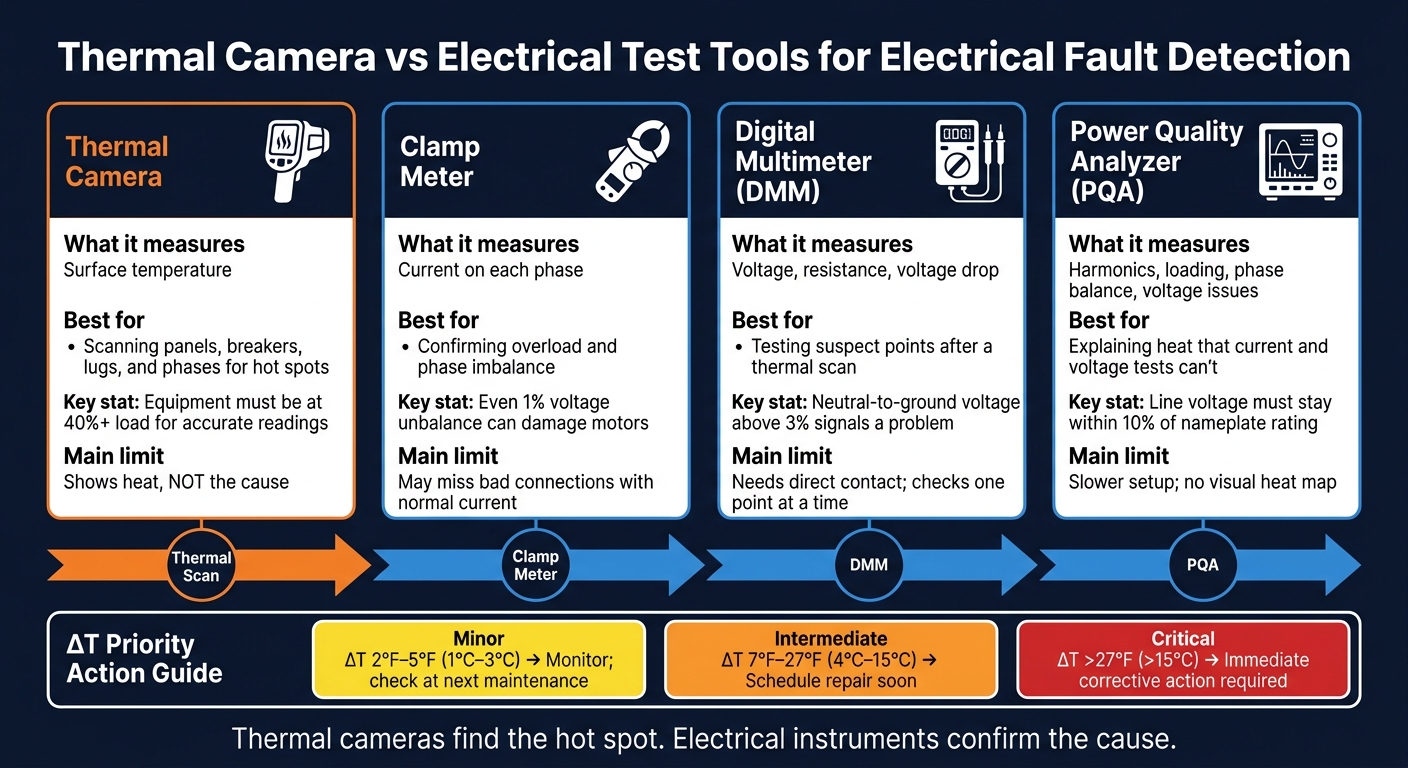
A thermal camera can show you a hot spot fast, but it can’t tell you the cause. If you’re checking electrical faults, the short answer is simple: use thermal imaging to find heat, then use a clamp meter, digital multimeter (DMM), or power quality analyzer (PQA) to confirm what’s wrong.
Here’s the core takeaway in plain English:
- Thermal cameras show surface heat from a safe distance
- They work best when equipment is at 40% load or more
- A hot part that is more than 27°F (15°C) above a similar part needs immediate action
- Heat alone can point to overload, loose connections, imbalance, or harmonics
- That means you still need meter tests to learn why the part is heating
If I had to sum up the whole article in one line, it would be this: thermal cameras are for finding the problem area; electrical test tools are for proving the fault.
Thermal Camera vs Electrical Test Tools: Which Finds Electrical Faults?
Finding Electrical faults with Thermal Camera - Hikmicro B10S Review

sbb-itb-501186b
Quick Comparison
| Tool | What I learn | Best use | Main limit |
|---|---|---|---|
| Thermal Camera | Surface temperature | Scan panels, breakers, lugs, and phases for hot spots | Shows heat, not cause |
| Clamp Meter | Current on each phase | Check overload and phase imbalance | May miss bad connections with normal current |
| DMM | Voltage, resistance, voltage drop | Test suspect points after a scan | Needs direct contact |
| PQA | Harmonics, loading, balance, voltage issues | Check heat that current and voltage tests don’t explain | Slower setup and no heat image |
One example says it well: a breaker found in a 2026 inspection was 77°F (25°C) hotter than the other phases. The scan found the hot spot. Follow-up testing led to the cause: a loose terminal screw.
So if you want the simple answer before reading the rest: thermal cameras are fast, safe, and useful for first-pass checks - but they are not a final test tool.
1. Thermal Camera
Measures
A thermal camera reads the infrared energy coming off the surface of electrical parts and turns it into a heat image. It measures surface temperature only. It does not directly measure voltage, current, or resistance. When current gets too high or resistance goes up, heat builds at the surface. That change is what the camera shows.
Best For
Thermal cameras are great for finding trouble on energized equipment before it turns into downtime or a fire. They’re often used to spot:
- Loose or corroded connections
- Overloaded conductors
- Unbalanced three-phase loads
Fault Confirmation
Thermal imaging is good at flagging something that looks off, but it doesn’t tell you the full cause by itself. A hot terminal, for example, might point to a loose lug, an undersized conductor, or harmonic distortion. To confirm what’s going on, you still need follow-up testing with a clamp meter, DMM, or power quality analyzer.
Limits
Load matters a lot here. Equipment should be running at at least 40% of rated load for clear temperature differences to show up. If the circuit is lightly loaded, the scan can miss a problem and give you a false negative.
Access matters too. In many cases, panel doors need to be opened unless IR windows are already installed. That means following NFPA 70E arc flash rules and wearing the right PPE.
Surface finish can also throw off readings. Shiny materials may skew temperature results, and HVAC airflow can hide hot spots. A common fix is to adjust emissivity settings or use a high-emissivity marker.
Use the temperature spread in the table below to judge how fast you should respond.
| ΔT from Similar Component | Priority Level | Recommended Action |
|---|---|---|
| About 2°F–5°F (1°C–3°C) | Minor | Monitor; investigate during next maintenance |
| About 7°F–27°F (4°C–15°C) | Intermediate | Schedule repair; probable deficiency present |
| >27°F (>15°C) | Major/Critical | Immediate corrective action required |
2. Clamp Meter
Measures
A clamp meter measures current on each phase and helps you check whether a thermal hot spot comes from overload or imbalance. In plain English, it’s the tool you grab after a thermal scan points to a problem area.
Best For
A clamp meter is the main tool for confirming overloads in panels, feeders, and branch circuits. It shows whether current is above a conductor’s rating and whether current is even across all three legs in a three-phase system.
It can also help spot sudden current spikes. When that happens, you may be looking at a short circuit or a faulted branch.
Fault Confirmation
A hot fuse or conductor tells you where the problem is, but not why. Clamp readings help sort out whether the cause is overload, phase imbalance, or contact resistance.
That’s the big difference between the two tools: thermal imaging points to a clue, while clamp readings test the load behind it. If one phase runs hotter than the others, readings on all three legs can show whether current is uneven. NEMA notes that even 1% voltage unbalance can damage motors.
Limits
A clamp meter has blind spots. It can miss faults that don’t change current, such as loose or corroded connections that still carry a normal load. It also doesn’t show the exact physical spot inside the panel.
Use NFPA 70E PPE when working on energized equipment.
If current looks normal but the heat is still there, the next step is to check voltage, resistance, or harmonics.
3. Digital Multimeter
Measures
Once current checks narrow things down to a suspect circuit, the DMM helps verify what’s happening at exact test points. A digital multimeter (DMM) backs up thermal findings by measuring voltage, voltage drop across fuses and switches, resistance, and neutral-to-ground voltage. If neutral-to-ground voltage is above 3%, that points to a problem that needs more checking.
Best For
Use a DMM to confirm what the thermal camera is hinting at and to pin down the electrical cause. It gives you hard numbers - volts and ohms - instead of a heat image.
That matters because some faults don’t show up cleanly on a thermal scan. For example, insulation resistance breakdown inside motor windings or intermittent faults may need direct meter readings to prove what’s going on.
Fault Confirmation
The readings that help most are voltage drop, resistance, and neutral-to-ground voltage. A hot fuse on one end usually points to high contact resistance. Heat on both ends usually suggests overload or imbalance.
In plain terms, the thermal camera shows you where to look. The multimeter tells you what the electrical issue is.
Limits
A DMM needs direct contact with energized components, so it’s slower and carries more risk than thermal scanning when you’re surveying a large area. It also checks one point at a time, while a thermal camera can scan many connections in a single pass.
If voltage and resistance readings look normal but heat is still there, the next step is a power quality analyzer for harmonic and transient checks.
4. Power Quality Analyzer
Use a PQA when a thermal scan shows heat, but current and voltage still need an explanation.
Measures
If clamp and multimeter checks still don't explain the hot spot, a power quality analyzer fills that gap. A power quality analyzer (PQA) measures current balance, phase loading, neutral-to-ground voltage, harmonic current, and voltage drop. Those readings help explain heat that a thermal scan can spot but can't diagnose on its own.
Best For
A PQA is the best next step when a thermal image is unclear. That's because overloads, bad connections, and harmonic imbalance can all create the same heat pattern. The PQA helps answer the why behind the hot spot.
Fault Confirmation
When a thermal camera flags a warm conductor, a PQA can show whether the heat is coming from overload, an undersized conductor, or harmonic distortion pushing extra current into the neutral. A neutral-to-ground voltage above 3% calls for more checking. Line voltage should stay within 10% of nameplate, and even a 1% voltage unbalance can overheat motors.
Limits
A PQA needs clamps or probes attached to the circuit, so it's slower and more intrusive than a thermal scan. It also doesn't give you a visual map of where the heat is building up. It can tell you which phase is affected, but not the exact point of failure. It's less useful for a hard short circuit and more useful for recurring overload, imbalance, or harmonic heating.
Thermal Cameras for Electrical Faults: Pros and Cons
Thermal imaging is one of the fastest ways to check energized equipment for hot spots. You can scan live gear in a short amount of time, which makes it useful for finding places that need a closer look.
But there’s a catch: it only shows surface heat.
That’s why thermal imaging works best as a screening tool, not a final diagnosis. It tells you where to look next, not why the problem is happening.
| Pros | Cons |
|---|---|
| Non-contact: Inspect energized equipment from a safe distance, often outside the NFPA-restricted approach boundary. | Surface only: Cannot see through closed metal covers or solid enclosures. |
| Fast scanning: Evaluate hundreds of connection points and entire panels in minutes. | Needs sufficient load: Faults may stay hidden if the system is running below 40% of rated load. |
| Early detection: Spots resistive heating long before smoke, physical damage, or failure occurs. | Does not identify the cause: Cannot distinguish between an overload, a loose connection, or harmonic distortion by image alone. |
| ΔT ranks repair urgency. | Environmental interference: Wind, solar heating, and reflective surfaces can skew readings. |
| Requires trained interpretation: Correct emissivity settings and reflection compensation are essential. |
A good example came from a 2026 scan of electrical panels. A circuit breaker was running 77°F (25°C) hotter than the other phases, so it was flagged for follow-up. The issue turned out to be a loose terminal screw. After it was tightened, a second scan showed the temperature had returned to normal.
That’s the practical value of thermal imaging. It points you to the hotspot fast. Then you match that hotspot to the right follow-up test, because the camera shows where to test next, while other tools tell you why the circuit is heating.
How to Choose and Use a Thermal Camera for Electrical Inspections
Not every thermal camera is a good fit for electrical work. If you're checking for overloads or short circuits, the camera needs to show small targets with enough detail to be useful. For this type of inspection, thermal cameras often cost between $400 and $7,000.
When you're comparing cameras, five specs matter most:
| Specification | Why It Matters for Electrical Work | Common Inspection Need |
|---|---|---|
| Focus Quality | Manual or motorized focus is required; fixed-focus units cannot resolve small components such as cable lugs or breaker terminals. | Suspect terminations, small lugs |
| Spatial Resolution (IFOV) | If the target is smaller than the spot size, the reading blends into background temperature. | Small components, distant targets |
| Thermal Sensitivity (NETD) | Units should have a thermal sensitivity of 50 mK or better to resolve small temperature differences in noisy field conditions. | Phase imbalance, high-resistance joints |
| Temperature Range | The device must support elevated temperatures so severely overloaded or deteriorating components do not max out the sensor. | Overloaded circuits, failing breakers |
| Measurement Accuracy | Accurate readings depend on correct emissivity, reflected temperature, and distance inputs, along with regular calibration. | Severity assessment, reporting |
Once you have the right camera, use it under normal operating conditions. That usually means checking equipment at peak load, or at least at 40% of its usual load. Then compare like-for-like parts side by side - for example, L1 vs. L2 vs. L3 on the same breaker.
Surface finish matters more than many people expect. Bare copper and aluminum can reflect infrared energy from nearby sources, which can throw off the reading. To get a steadier target, adjust the camera's emissivity settings or, when safe, place a small strip of electrical tape on the spot you're measuring.
It also helps to document baseline thermal images for every component you scan, not just the ones that look hot. That's what gives you a history to compare against later and makes slow-developing faults easier to catch.
If a scan shows something off, don't stop at the image. Use a clamp meter to check actual current draw and phase balance, a digital multimeter to measure voltage drop across terminations, or a power quality analyzer if harmonics may be heating the neutral conductor. The thermal camera helps you find the hotspot. The meters help you confirm what's causing it.
Conclusion
Thermal cameras are great for fast, noncontact checks of energized equipment. They help you spot hot areas before something fails.
But a thermal image shows heat, not the reason behind it. Overload, imbalance, loose connections, and harmonic issues can all look alike in the image. That’s why you need electrical testing to figure out what’s going on.
Use thermal imaging to find the hot spot. Then verify the cause with tools like a clamp meter, digital multimeter, or power quality analyzer.
Put simply: thermal cameras find problems fast; electrical instruments confirm them.
FAQs
Can a thermal camera find a loose connection?
Yes. A thermal camera can help identify loose electrical connections because those faults often create extra heat from higher electrical resistance.
In practice, these problems usually show up as isolated hot spots at terminations, connectors, and contact points. That matters because the pattern is different from an overloaded circuit, which tends to produce a more even heat pattern across the affected area.
Why can’t a thermal image confirm the exact fault?
A thermal camera shows temperature-related symptoms. It does not tell you the root cause of an electrical fault on its own.
That matters because similar heat patterns can come from different problems. The same hot spot might point to an overload, a loose connection, or a harmonic imbalance. At a glance, they can look almost the same.
Thermal readings can also shift based on outside conditions, load, and emissivity. So the image is useful, but it isn't the whole story.
To pinpoint the exact fault, pair thermal imaging with other checks, such as an ammeter reading or a visual inspection.
What tool should I use after finding a hot spot?
After you identify a hot spot, use an ammeter to check the electrical load or power quality. A true RMS ammeter is especially useful here because it helps confirm what you found.
Those readings can point to the cause of the heat, such as an overload, a loose or corroded connection, or a phase imbalance.


