




NEC Article 392: Cable Tray Installation Rules
NEC Article 392 outlines the key rules for installing and maintaining industrial cable tray systems. These systems, made from metal or plastic, are open structures designed to support electrical conductors, ensuring proper organization and safety. Here's what you need to know:
- Cable Types: Only use conductors rated for open-air environments, such as Tray Rated (Type TC) or Metal-Clad (Type MC) cables.
- Clearances: Maintain at least 12 inches of vertical clearance above trays for installation and maintenance access (2026 NEC update).
- Prohibited Areas: Cable trays cannot be used in hoistways or enclosed spaces and must remain accessible.
- Grounding: Metallic trays can serve as equipment grounding conductors (EGC) if they meet NEC requirements.
- Fill Limits: For power cables, the fill must not exceed 40% of the tray's cross-sectional area; for control cables, it's 50%.
- Separation: High-power and low-power cables must be separated to prevent electromagnetic interference (EMI).
- Materials: Choose the tray material - aluminum, steel, or FRP - based on environmental conditions and load requirements.
Proper installation minimizes risks like overheating, fire, and mechanical failure while ensuring compliance with NEC standards. The latest updates also emphasize safety improvements, such as stricter clearance and spacing requirements. Following these guidelines can help avoid costly errors and ensure long-term system reliability.
Mastering NEC 392: Cable Tray Installation Best Practices

sbb-itb-501186b
Where Cable Trays Can and Cannot Be Used
This section explains where cable trays are appropriate and where their use is restricted. Knowing these details can help you stay compliant and avoid costly errors.
Allowed Applications
Cable trays are commonly used in industrial facilities, commercial offices, and factories where maintenance access is readily available. They are approved for supporting various types of circuits, including service conductors, feeders, branch circuits, communications circuits, control circuits, and signaling circuits. For installations involving numerous conductors, experts often recommend cable trays as a practical solution.
In industrial setups, single insulated conductors can be used in cable trays if they are 1/0 AWG or larger. Cable trays can also be used to transition conductors into equipment through bushed conduit, tubing, or flanged connections. When installed outdoors or in areas exposed to sunlight, it’s important to use sunlight-resistant cables and expansion splice plates to accommodate thermal expansion and contraction.
Following these guidelines ensures compliance with NEC standards and promotes safer installations.
Restricted Applications
Despite their versatility, cable trays are not suitable for every situation.
They are strictly prohibited in hoistways or any location where they could face severe physical damage. Cable trays must remain in open, accessible areas to allow for proper maintenance. They should never be permanently enclosed, and if they pass through walls or partitions, proper fire-stopping measures must be in place to prevent the spread of fire.
Nonmetallic cable trays come with additional limitations. These are typically allowed only in corrosive environments or where voltage isolation is necessary. In plenum spaces, standard plastic cable ties are not permitted; instead, fire-rated ties must be used to reduce the risk of toxic smoke during a fire.
Another important restriction involves separating high-power motor wires from low-power data cables within the same tray. Without a solid, non-combustible barrier, electromagnetic interference can occur. Lastly, single conductor cables smaller than 1/0 AWG are generally not allowed in cable trays, except under specific conditions in industrial applications.
Understanding these restrictions helps ensure both safety and compliance.
Cable Tray Types and Materials
Picking the right cable tray design and material is essential for ensuring both effective performance and compliance with safety standards. The three main designs - ladder, solid-bottom, and ventilated trough - each address specific needs like heat management, cable support, and EMI shielding.
Ladder trays are widely used in industrial environments. They excel in cooling heavy power cables by allowing heat to escape efficiently. For single conductor cables ranging from 1/0 AWG to 4/0 AWG, ensure the rungs are spaced no more than 9 inches apart.
Solid-bottom trays provide continuous shielding against electromagnetic interference (EMI), making them ideal for sensitive circuits like data and control cables. However, this design can trap heat, reducing cable ampacity by 20% to 50%. Use these trays when EMI protection is a higher priority than ventilation.
Ventilated trough trays are designed for smaller cables, offering both support and airflow. They prevent small-diameter instrumentation cables from sagging between rungs while also enabling better heat dissipation compared to solid-bottom trays.
When it comes to materials, the choice depends on the application and environment. Aluminum is lightweight and corrosion-resistant, making it suitable for many applications. Steel provides durability for heavy-duty use, while FRP (fiber-reinforced plastic) is ideal for corrosive environments. If you're using nonmetallic trays, they must be listed for areas requiring corrosion resistance and voltage isolation. To prevent galvanic corrosion on aluminum trays, always use bimetallic sandwich washers.
Up next, we’ll dive into the specific installation requirements to ensure your setup meets NEC standards.
Installation Requirements
Following NEC installation guidelines is essential to safeguard cables and maintain the overall integrity of industrial systems. According to NEC 392.18(A) and (B), the cable tray system must be fully assembled before pulling conductors. This step minimizes the risk of cable damage during the construction phase and ensures the system remains structurally sound.
Support and Spacing Requirements
Support spacing for cable trays must align with the manufacturer's instructions, as outlined in NEC 392.30(A). Generally, standard trays require supports every 6 to 10 feet, while heavy-duty, long-span trays can handle distances of up to 20 feet between supports. To determine the proper spacing, consult the manufacturer's load capacity chart, which accounts for the total weight of the cables.
The 2026 NEC introduced an important update: cable trays must have at least 12 inches of clear vertical space above them to allow for installation and maintenance access.
When transitioning cables from a tray to equipment or another raceway, the unsupported span cannot exceed 6 feet. If this distance is greater, additional supports are required to prevent undue mechanical stress on the conductors. For extended outdoor runs, expansion splice plates should be installed to accommodate thermal expansion and contraction.
How to Secure Cables and Conductors
In vertical or angled tray runs, cables should be fastened to the tray's transverse members to keep them secure. In horizontal runs, the weight of the cables often keeps them in place, but adding ties can help maintain spacing, which improves heat dissipation. It's important to use cable ties that are listed and approved for cable tray applications - standard plastic ties may not meet fire-safety standards, especially in plenum spaces.
At transition points, such as where cables enter raceways or connect to equipment, secure the cables to the tray and provide strain relief to protect terminations. Take care not to overtighten ties, as this can damage the cable jackets and lead to long-term issues. For outdoor installations, only use UV-resistant ties, as standard ties can degrade and fail within 1 to 2 years when exposed to direct sunlight.
Wiring Methods and Fill Calculations
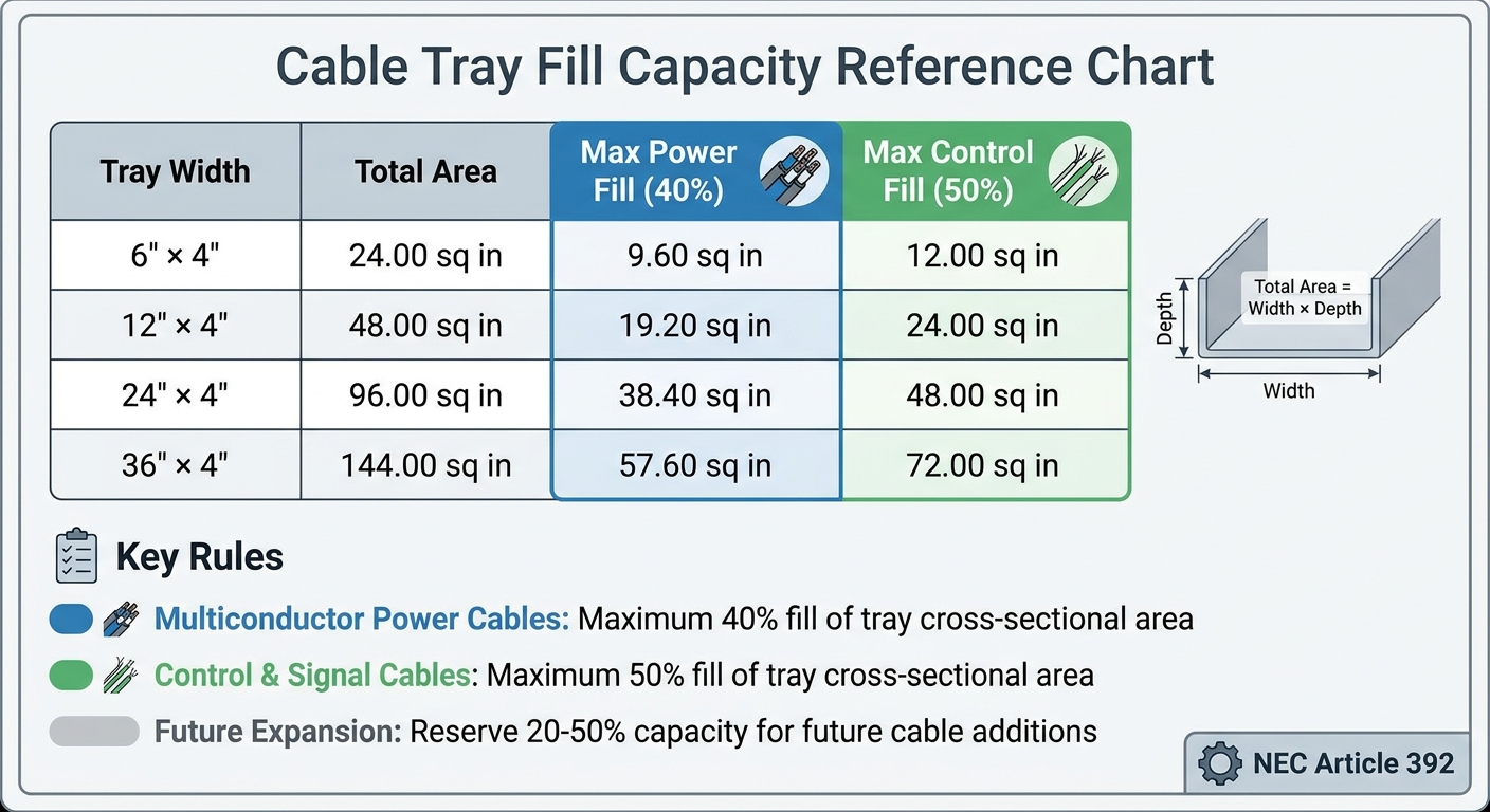
NEC Cable Tray Fill Capacity Chart by Tray Width and Cable Type
Properly calculating cable tray fill capacity is essential to avoid overheating, equipment damage, and code violations. You can determine the fill by dividing the total cable area by the tray's usable area (Width × Depth). However, the National Electrical Code (NEC) Article 392 sets specific fill limits based on the type of cables being installed.
For multiconductor power cables, the combined cross-sectional areas of all cables must not exceed 40% of the tray's total area. On the other hand, control and signal cables are allowed a higher fill limit of up to 50%.
Senior Electrical Engineer Nadeem Sial explains: "The NEC 40% fill rule (NEC Article 392) states that for trays containing multiconductor power, lighting, or signal cables, the sum of the cross-sectional areas of all cables must not exceed 40% of the tray's total cross-sectional area".
Here’s a quick reference for standard 4-inch depth trays:
| Tray Width | Total Area | Max Power Fill (40%) | Max Control Fill (50%) |
|---|---|---|---|
| 6" × 4" | 24.00 sq in | 9.60 sq in | 12.00 sq in |
| 12" × 4" | 48.00 sq in | 19.20 sq in | 24.00 sq in |
| 24" × 4" | 96.00 sq in | 38.40 sq in | 48.00 sq in |
| 36" × 4" | 144.00 sq in | 57.60 sq in | 72.00 sq in |
This table helps match tray dimensions with both current and anticipated future loads. It's wise to allocate 20% to 50% of capacity for future expansion, as adding a second tray system later can be much more expensive than slightly oversizing the initial installation.
Single Conductor Cables (1/0 AWG and Larger)
When working with single conductors sized 1/0 AWG or larger, additional considerations apply. For conductors of 1,000 kcmil and above, they must be installed in a single layer, ensuring their combined diameters do not exceed the tray width. Similarly, for single conductors between 1/0 and 4/0 AWG, the total of all diameters must also fit within the tray width.
Solid bottom trays can restrict airflow, which reduces ampacity by 20% to 50% compared to ladder trays. This is why ladder trays are often preferred for heavy power applications - their open design promotes better air circulation, keeping conductors cooler.
Multiconductor Cables
Multiconductor cables operating at 600 volts or less can be installed together in the same tray without needing internal barriers or special spacing. To calculate fill:
- Measure the outer diameter of each cable.
- Compute its area using the formula: π × (D/2)².
- Add up all the cable areas.
The total must remain under 40% for power cables or 50% for control and signal cables. Only cables specifically rated for tray use - such as Type TC (Tray Rated) or Type MC (Metal-Clad) - are allowed. Additionally, ensure cables are separated based on operating voltages to prevent interference.
Voltage Separation Requirements
Beyond fill calculations, maintaining proper voltage separation is crucial for safety and to reduce electromagnetic interference (EMI). According to NEC 392.20, the separation is based on the operating voltage, not the insulation rating. Cables operating above 600 volts must be separated from those operating at 600 volts or less unless the higher-voltage cables are Type MC (Metal-Clad). If Type MC is not used for circuits over 600 volts, a solid, fixed barrier made of compatible material must be installed to separate them from lower-voltage cables.
Mixing high-power cables with low-power signal cables (like data or internet lines) in the same tray is not recommended unless a solid divider wall is used. EMI from power cables can disrupt the signal integrity of low-power lines. When checking compliance, focus on the actual operating voltage. For example, cables with different insulation ratings (such as 600V and 1,000V) can share the same tray without a barrier as long as all circuits operate at 600 volts or less.
Grounding and Bonding
To ensure your cable tray system operates securely and complies with NEC standards, grounding and bonding are essential steps to follow.
All metallic cable trays must be grounded as outlined in NEC Article 250.96, even if the tray isn't being used as an equipment grounding conductor (EGC). This precaution helps prevent electrical shocks and equipment malfunctions. Edvard Csanyi, Founder of Electrical Engineering Portal, emphasizes the importance of grounding:
"The EGC is the most important conductor in an electrical system as its function is electrical safety".
You have three main options for incorporating an EGC into your cable tray system:
- Separate EGC Conductor: Install a separate EGC conductor (minimum size #4 AWG) either inside or attached to the tray.
- Multiconductor Cables: Use cables that include individual EGCs within their jackets.
- Cable Tray as EGC: In maintained facilities, the tray itself can serve as the EGC if it meets the cross-sectional area requirements in Table 392.60(A). Keep in mind, steel trays are limited to circuits with ground-fault protection up to 600 amperes, while aluminum trays can handle up to 2,000 amperes.
Once your grounding method is in place, bonding becomes equally crucial for safety. Bonding ensures electrical continuity across components like expansion splice plates, adjustable sections, or other discontinuities. Use listed connectors or bonding jumpers to maintain a low-impedance fault current path. For long outdoor runs, thermal expansion can cause significant movement - an aluminum tray spanning 100 meters can shift by several centimeters with seasonal temperature changes. Flexible bonding jumpers at expansion joints allow for this movement while preserving the ground path.
When dealing with mixed materials, corrosion prevention is key. For example, placing bare copper EGCs in aluminum trays in moist conditions can lead to electrolytic corrosion, compromising the safety ground. To avoid this, opt for insulated conductors, stripping the insulation only at bonding points. Additionally, use bimetallic washers to prevent galvanic corrosion. Cable Tray Fab highlights the risks:
"The safety ground fails when this metal disintegrates. To avoid this, it is always necessary to use bimetallic washers".
For added security, anchor separate EGC conductors with grounding clamps every 10 to 20 feet. This prevents magnetic forces from displacing the conductor during fault conditions. While not a strict NEC requirement, bonding the EGC to the tray every 50 to 100 feet provides a parallel, low-impedance path that reduces shock risks. This extra measure is especially important for trays carrying signal or control cables.
Compliance Tips for Industrial Installations
Ensuring compliance with NEC Article 392 in industrial setups requires close attention to details inspectors often highlight. These tips expand on earlier installation and grounding practices to help maintain a compliant and safe industrial environment.
One frequent issue is misunderstanding the purpose of cable trays. As CableTrayFab puts it:
"A cable tray is a support structure that seems to be a bridge that supports wires in the air".
This misconception leads to about 25% of installation errors, often involving the use of incorrect cable types. Instead of using Type TC (Tray Rated) or Type MC (Metal-Armored) cables, installers may mistakenly select inappropriate alternatives.
Another critical point is avoiding overfilling cable trays. Overloading trays beyond the fill capacities outlined in NEC 392.22 can trap heat, increasing the risk of insulation damage or even fire. Stick to the 50% fill rule for control cables, and always layer power cables flat to promote heat dissipation.
In industrial environments, reduced clearances are acceptable only if access is limited to qualified personnel. Proper documentation must clearly reflect this arrangement to meet compliance standards.
For long outdoor runs, thermal expansion can’t be overlooked. A 100-meter aluminum tray, for example, can shift by several centimeters between summer and winter due to temperature changes. To handle this movement, expansion splice plates should be installed. Additionally, when combining copper grounding components with aluminum trays, use bimetallic washers to prevent galvanic corrosion.
When power and signal cables share the same tray, solid dividers should be installed to reduce electromagnetic interference. In plenum spaces, only fire-rated cable ties listed for tray systems should be used. Regular plastic ties may release toxic smoke in the event of a fire, posing a serious hazard .
Conclusion
Following NEC Article 392 is essential for ensuring safety and efficiency in industrial cable tray installations. Unlike enclosed conduits, cable trays are open support systems, which influences how wires are selected and fill calculations are made. As CableTrayFab puts it, "Adherence to the principles of Article 392 is not only about keeping safe; it is also about doing a better job".
Proper installation helps prevent issues like overheating, grounding failures, and structural problems. Using tray-rated Type TC or metal-armored Type MC cables, staying within fill limits, and choosing UL-classified components for grounding are all critical steps for building a compliant system. These practices not only ease inspections but also enhance long-term performance.
The NEC 2026 updates bring additional refinements, such as the requirement for a 12-inch minimum clearance above trays to allow for maintenance access.
Investing in quality components - like bimetallic washers, fire-rated cable ties, UL-listed tray sections, and correctly rated expansion joints - can make a big difference in passing inspections the first time. For compliant electrical components and power distribution equipment, Electrical Trader offers a wide selection tailored to NEC Article 392 requirements.
Planning for future capacity, alongside careful attention to thermal management, voltage separation, and grounding, ensures a safe and durable cable tray system for years to come.
FAQs
How do I choose between ladder, solid-bottom, and ventilated trough trays?
Choosing the right cable tray comes down to your specific application, the type of cables you're using, and the environment they're in. Here's a quick breakdown of the main options:
- Ladder trays: These are a go-to choice for industrial settings. They offer great ventilation, allow heat to escape easily, and make cable access simple for maintenance or upgrades.
- Ventilated trough trays: Perfect for high-density installations, these trays provide enough airflow to keep cables from overheating.
- Solid-bottom trays: If you're dealing with dusty, corrosive, or hazardous environments, these trays are ideal. They shield cables from debris and potential damage.
When selecting a cable tray, think about how much ventilation your cables need, the level of protection required, and how often you'll need to perform maintenance.
When can the cable tray itself count as the equipment grounding conductor (EGC)?
The cable tray can act as the equipment grounding conductor (EGC) if it meets specific conditions. It must be clearly identified as an EGC, properly bonded to maintain electrical continuity, and installed according to National Electrical Code (NEC) standards. Additionally, regular maintenance and oversight by qualified professionals are essential to ensure safety and compliance.
How do I calculate tray fill when mixing power and control cables?
To figure out tray fill, start by calculating the tray's cross-sectional area. Next, determine the area of each cable type and add them together. Once you have the total cable area, divide it by the tray's usable area and multiply the result by 100 to get the percentage. According to NEC Article 392, the fill is generally limited to 40% for power cables and 50% for control cables. These limits help ensure proper ventilation and maintain safety standards.





