NEC 430.53 Rules for Multiple Motors
You can put more than one motor on one branch circuit only if the setup fits NEC 430.53(A), (B), or (C). If it does not, the circuit is not compliant.
Here’s the short version: each motor still needs its own overload protection, the shared branch-circuit protection must be a fuse or an inverse-time circuit breaker, and the circuit has to stay within controller markings, SCCR limits, disconnect rules, and conductor sizing rules. On conductor sizing, the article points to 125% of the largest motor FLC plus 100% of the other motor loads under 430.24, using NEC motor tables instead of nameplate current.
If I had to boil the whole article down to a few checks, it would be these:
- 430.53(A): only for small motors, 1 hp or less and 6 A FLC or less per motor
- 430.53(B): the branch OCPD is limited by the smallest motor in the group
- 430.53(C): use the listed group motor assembly markings and follow them exactly
- Every motor: needs individual overload protection
- Disconnects: must meet 430.102 rules for location and function
- Conductors: size from the motor group load, not just the breaker size
- Common errors: wrong FLC source, oversized OCPD, ignored SCCR, and poor disconnect placement
Multiple Motors on One Branch Circuit OCPD Calculation
sbb-itb-501186b
Quick Comparison
| Method | Main limit | Best fit |
|---|---|---|
| 430.53(A) | Each motor must be ≤ 1 hp and ≤ 6 A FLC | Small grouped motors |
| 430.53(B) | OCPD cannot exceed what 430.52 allows for the smallest motor | Mixed motor groups when starting conditions work |
| 430.53(C) | Must match the listing and marked assembly ratings | MCCs, packaged machinery, factory-built panels |
Bottom line: I’d treat NEC 430.53 as a short list of allowed paths, not a general permission to group motors on one breaker. The article is mostly a guide to picking the right path, sizing the conductors and OCPD correctly, and avoiding the mistakes that lead to failed inspections or shutdowns.
The Three NEC 430.53 Group Motor Methods
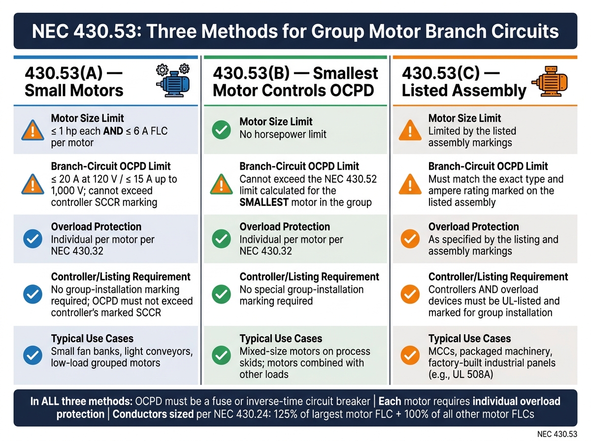
NEC 430.53 Group Motor Methods: A-B-C Comparison Chart
NEC 430.53 allows group motor branch circuits only under 430.53(A), (B), or (C). In all three cases, the branch-circuit OCPD has to be either a fuse or an inverse-time circuit breaker. The key point is simple: each method has its own limits, and you use one method at a time. It makes sense to start with the easiest route first, then move to the listed-assembly method if needed.
430.53(A): Small Motors Not Over 1 HP on One Branch Circuit
This is the most straightforward option. Each motor must be rated 1 hp or less, have a full-load current (FLC) of no more than 6 A, and have its own overload protection under 430.32. The branch-circuit OCPD is capped at 20 A on 120 V circuits and 15 A on circuits up to 1,000 V. It also can't be higher than any short-circuit/ground-fault rating marked on the motor controllers.
In industrial panels, 430.53(A) works well for small fan banks, light conveyors, and other low-load groups. But there's no wiggle room here. If even one motor is over 1 hp or above 6 A FLC, this method is off the table.
430.53(B): Branch-Circuit Protection Based on the Smallest Motor
430.53(B) gives you more room. It lets you group motors of any size, or even combine motors with other loads, on one branch circuit. The catch is that the branch-circuit OCPD can't be more than what NEC 430.52 allows for the smallest motor in the group.
That rule can trip people up. Say the smallest motor and the OCPD type you picked allow a maximum of 175% of FLC under 430.52. Then the group OCPD can't go above that limit, even if the other motors are much larger. Each motor still needs its own overload protection. On top of that, the OCPD has to be chosen so it won't open during the worst normal operating condition, like simultaneous starts.
This method tends to fit setups where the control scheme keeps motors from all starting at once.
430.53(C): Controllers Marked for Group Installation
430.53(C) is the engineered-system route. It applies when the motor controllers and overload devices are UL-tested, listed, and clearly marked as suitable for group installations. In this setup, the listed assembly tells you what OCPD, controllers, and overloads are allowed.
You have to use the OCPD type and rating marked on that listed assembly. Manufacturers spell out the maximum fuse or breaker size, and the installation has to stay within those markings. Tap-conductor rules in 430.53(D) also come into play, with choices based on conductor ampacity and physical length limits.
You'll see this method a lot in MCCs, factory-built panels, and packaged machinery where the OEM has already done the testing, such as under UL 508A. In the field, the installation has to match the manufacturer's instructions exactly.
Quick comparison:
| Criteria | 430.53(A) | 430.53(B) | 430.53(C) |
|---|---|---|---|
| Motor size limit | ≤ 1 hp each; FLC ≤ 6 A | No hp limit | Limited by the listing |
| Branch-circuit OCPD limit | ≤ 20 A at 120 V; ≤ 15 A up to 1,000 V | Must not exceed the 430.52 limit for the smallest motor | Must match the type and rating marked on the listed assembly |
| Overload protection | Individual per motor per 430.32 | Individual per motor per 430.32 | As specified by the listing and assembly markings |
| Controller/listing condition | OCPD cannot exceed the controller's marked short-circuit rating | No special group-installation marking required | Controllers and overloads must be listed and marked for group installation |
| Typical use cases | Small fan banks, light conveyors, low-load groups | Mixed-size motors on process skids; motors plus other loads | MCCs, packaged machinery, factory-built industrial panels |
With the method picked, the next check is conductor sizing and the tap rules.
Sizing the Branch Circuit, Conductors, and Protection
Once you've picked the group method, the next job is to size the OCPD, conductors, and any taps to fit that method.
Branch-Circuit Short-Circuit and Ground-Fault Protection Limits
Size the OCPD based on the method in use. 430.53(A) uses fixed ampere caps, 430.53(B) uses the lowest-FLC motor in the group, and 430.53(C) uses the marked limit on the listed assembly. Under 430.53(B), take the FLC of the lowest-FLC motor in the group, apply the matching percentage from Table 430.52, and make sure the breaker or fuse does not go past that value. Under 430.53(C), the OCPD still has to stay within the 430.52 limit and also cannot exceed the maximum marked on the listed assembly.
One detail matters here: round only to the next standard ampere size that still stays within the allowed limit.
Under 430.53(B), the lowest-FLC motor controls the OCPD. That's the key check.
After that, shift to the conductors. Size them from the motor group load, not from the branch-device rating.
Conductor Ampacity and Tap Rules for Multiple Motors
Size multi-motor branch-circuit conductors under NEC 430.24. Start with 125% of the FLC of the highest-rated motor. Then add 100% of the FLC of each other motor in the group. If the same circuit also carries non-motor loads, add 100% of noncontinuous loads and 125% of continuous loads.
Minimum ampacity = 1.25 × FLC<sub>largest motor</sub> + Σ(FLC<sub>other motors</sub>) + 100% of noncontinuous non-motor loads + 125% of continuous non-motor loads.
This is where people sometimes slip up: use NEC Tables 430.247–430.250, not the motor nameplate, for the calculation. NEC 430.6(A) requires that method.
For tap conductors under 430.53(D), keep the tap short, place controllers as close to the tap point as possible, and make sure each motor on the tap still has individual overload protection. Those tap-length and controller-location rules tie straight into the disconnect placement rules in the next section.
A Simple Hypothetical Sizing Example
For a 10 hp / 5 hp / 3 hp group, size the conductors from the largest motor and size the OCPD from the lowest-FLC motor in the group.
Next comes controller markings and disconnect placement.
Controllers, Disconnects, and Common Layout Mistakes
Controller Listings, Overloads, and Disconnecting Means
Getting the sizing right is only half the job. The other half is the physical setup - where the controllers, overloads, and disconnects sit in relation to each motor. That’s where a lot of installs run into inspection problems.
Each motor still needs its own overload protection under NEC 430.32. A shared branch OCPD does not take the place of that device. And that overload device has to be part of a listed motor controller assembly.
For 430.53(C), the listed assembly governs both the controller package and the overload devices. Controllers and overload devices must be listed and marked for group installation. Each controller and panel also needs an SCCR that is at least equal to the available fault current. If one downstream controller has a lower SCCR, it can drag the whole panel down to that lower value.
NEC 430.102 calls for a disconnect for each motor controller and motor, within sight, and able to open all ungrounded conductors. When several motors are set up as parts of one machine or apparatus, one disconnect can serve a machine group - but only when the installation and rating rules allow it. In some cases, the controller disconnect can also serve as the motor disconnect if it is in sight of both the motor and the driven machinery.
Labels matter too. Every disconnect should be plainly marked so it’s clear what it controls, and that marking should match the wiring diagram.
Common Design and Installation Errors in Multi-Motor Circuits
The table below shows the mistakes that come up most often in multi-motor branch-circuit installations and why they matter:
| Error | Why It's a Problem |
|---|---|
| Using motor nameplate current instead of NEC table FLC | Can undersize conductors and overcurrent devices |
| Applying the wrong group method for the motor sizes involved | Branch-circuit protection won't match NEC limits |
| Oversizing the branch-circuit breaker beyond NEC limits | Reduces fault protection and can exceed controller SCCR |
| Ignoring SCCR markings on controllers | Components can fail during a fault |
| Omitting individual overload protection for each motor | Violates 430.32 and creates overheating/reliability issues |
| Applying feeder tap rules to branch-circuit conductors | Misaligns conductor ampacity, OCPD sizing, and tap rules |
| Placing the only disconnect out of sight of the equipment it serves | Fails in-sight requirements and often triggers inspection issues |
| Starting all motors simultaneously on a shared branch circuit | Combined inrush can cause voltage dips and nuisance trips |
Next, match these ratings to the actual breakers, fuses, controllers, and disconnects you buy.
Equipment Selection and Final Compliance Checks
What to Verify Before Buying Breakers, Fuses, Controllers, and Disconnects
Once the circuit layout is set, make sure the parts you buy line up with the circuit ratings and required markings. This is the last place you want a mismatch.
| Specification | What to Confirm |
|---|---|
| Voltage rating | Listed for the system voltage and phase |
| Ampere rating | Matches the chosen 430.53 method and conductor ampacity |
| OCPD type | Use only the fuse or inverse-time breaker allowed by the selected 430.53 method |
| Interrupting rating | Breakers and fuses: interrupting rating at least equal to available fault current |
| SCCR | Controllers and assemblies: SCCR at least equal to available fault current |
| Controller group-installation marking | Required only for 430.53(C) |
| Overload compatibility | Overload relay must match the motor's full-load current and motor type per NEC 430.32 |
| Disconnect hp rating | Must have an adequate hp rating at the operating voltage and a lockable OFF position for safe isolation |
| Enclosure type | Choose an enclosure rated for the installation environment |
| Conductor termination range | Lugs must fit the selected conductor size and material |
For 430.53(C) installations, the listed assembly drives the next step. Before you buy anything, check the manufacturer's SCCR table. That rating only applies when you use the exact breaker or fuse types and sizes shown there. Swap in a different part, and the listed rating may no longer apply.
If you source breakers or MCC buckets through Electrical Trader, check that the listing includes SCCR and interrupting-rating data that match the site's available fault current. No guesswork here.
Key NEC 430.53 Points to Remember
Use this as a final check before procurement or sign-off:
- Verify the selected OCPD, controllers, overloads, conductors, and taps all match the chosen method.
- Each motor still needs its own overload protection.
- Each motor also needs a clearly labeled disconnecting means.
FAQs
When can multiple motors share one branch circuit?
Under the NEC, more than one motor can be connected to the same branch circuit if the setup meets the code’s grouping rules.
This usually works when the motors are connected to a single controller or are grouped in a way the NEC allows. Each motor still needs its own overload protection, and the branch circuit has to be sized based on the total combined load.
The branch-circuit protective device also needs to be rated for that combined load, without going past the capacity of the circuit or the equipment.
How do I size conductors for a group of motors?
Size supply conductors at 125% of the full-load current of the largest motor, then add 100% of the full-load current for each other motor on the circuit.
There’s one more part that trips people up: conductor ampacity has to match the lowest temperature rating of any part of the system. So even if the wire can handle more, you still size from the weakest link.
Here’s the rule of thumb:
- For circuits rated 100A or less, use the 60°C column in NEC Table 310.16
- For circuits over 100A, use the 75°C column in most cases
That’s the basic path: start with the motor full-load currents, apply the 125% + 100% rule, then check ampacity using the proper temperature column.
Can one breaker replace individual motor overloads?
No. A properly sized branch-circuit breaker protects against short circuits and ground faults, but it usually does not take the place of motor overload protection during sustained overloads and overheating.
In industrial motor control systems, overload and overcurrent protection need to be set up for safe, code-compliant operation. And if you change any device, the new part needs to match the required ratings and coordination of the parts already installed.