
How Medium Voltage Circuit Breakers Protect Utility Networks
One medium-voltage breaker can stop a feeder fault from turning into a much bigger outage. In utility distribution, these breakers usually work in the 1.1 kV to 36 kV range, trip through CTs and relays, and clear many faults in about 40 to 80 milliseconds.
If I had to sum up the article in plain English, it comes down to this:
- MV breakers do not work alone. They rely on current transformers (CTs) and protective relays to spot trouble and send the trip signal.
- Their main job is isolation. They open only the faulted feeder or transformer section so the rest of the system can stay on.
- Fault interruption is a timed process. After the relay sends a trip signal, the breaker opens, an arc forms, and that arc must go out at the next current-zero point on a 60 Hz system, which comes every 8.3 milliseconds.
- Protection has to be selective. The device closest to the fault should trip first. If settings are wrong, more of the network can go dark.
- Vacuum and SF6 breakers serve different needs. Vacuum is common for many 11 kV to 33 kV feeder jobs. SF6 is still used where gas-insulated switchgear or high fault-duty demands call for it.
- Ratings and maintenance matter. Utilities need to match voltage class, continuous current, interrupting capacity, making current, altitude limits, and switching duty to the actual system.
A few numbers from the article stand out:
- Common MV classes include 4.16 kV, 7.2 kV, 13.8 kV, 24 kV, and 34.5 kV
- Vacuum interrupters may handle up to 30,000 mechanical operations
- But they may be rated for only about 50 full short-circuit interruptions at full duty
- Common continuous current ratings include 630 A, 800 A, 1,250 A, 2,000 A, and 3,150 A
- Sites above 3,280 feet (1,000 meters) may need derating
Quick comparison
| Breaker type | Where I’d expect to see it | Main point | Upkeep |
|---|---|---|---|
| Vacuum | Distribution feeders, transformer protection, switchgear | Sealed interrupter, no gas handling | Low |
| SF6 | GIS, compact substations, higher fault-duty service | Gas insulation and arc quenching | Gas checks and leak monitoring |
Bottom line: medium-voltage breakers protect utility networks by finding faults, tripping fast, and isolating only the damaged section. The breaker matters, but the relay settings, coordination, and correct ratings matter just as much.
How medium voltage circuit breakers work during switching and faults
How Medium Voltage Circuit Breakers Detect & Clear Faults
Fault detection, relays, CTs, and automatic tripping
Once selective protection picks out the faulted feeder, the breaker’s control circuit steps in. CTs send feeder current to the relay, and the relay watches for both fault trips and normal switching conditions. It compares that current signal against pickup and time settings for overcurrent and ground faults.
When the relay sees a fault, it sends a DC trip signal to the breaker’s trip coil. The trip coil then energizes a solenoid, which releases the spring mechanism and opens the contacts. From fault detection to arc extinction, the whole sequence usually takes 40 to 80 milliseconds.
That trip action kicks off the breaker’s interruption sequence.
Contact separation and arc interruption inside the breaker
Once the spring mechanism releases, the contacts part at high speed. As soon as they separate, a high-temperature arc forms. That arc has to go out at current zero. In a 60 Hz system, that chance comes every 8.3 milliseconds.
The breaker has a narrow job here: quench the arc at current zero and recover dielectric strength before the transient recovery voltage (TRV) restrikes the arc. If that sounds like a split-second balancing act, that’s because it is.
Load switching is much easier on the breaker. Fault interruption is a different story. It puts the device under much higher thermal and mechanical stress. That’s why vacuum interrupters are often rated for up to 30,000 mechanical operations, but only about 50 full short-circuit interruptions at rated capacity.
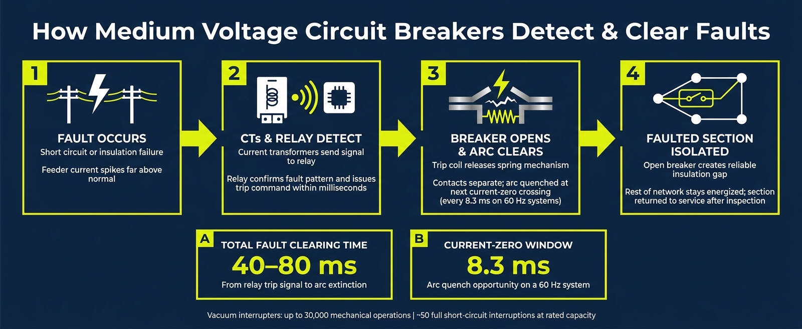
Step-by-step: from fault trip to service restoration
In day-to-day use, the process moves fast and in a set order:
- Fault occurs - A short circuit or insulation failure pushes feeder current far above normal levels.
- CTs and relay detect it - The CT signal reaches the relay, which confirms the fault pattern and sends a trip command within milliseconds.
- Breaker opens and clears the arc - The trip coil releases the spring mechanism, the contacts separate, and the arc is quenched at the next current-zero crossing. This keeps the outage limited to the faulted section.
- The faulted section is isolated and returned to service after inspection - The open breaker creates a reliable insulation gap. In withdrawable designs, the breaker truck can be withdrawn for safe access.
sbb-itb-501186b
Core protection functions that prevent equipment damage and wider outages
Overload protection for feeders and connected equipment
Fault clearing gets most of the attention, but overload protection matters just as much. The same relay scheme also guards against slower thermal damage caused by excess current over time.
MV breakers are built to carry a rated continuous current without going past thermal limits, often 630, 800, 1,250, 2,000, or 3,150 A. If current stays above that rating, the relay trips before heat can damage insulation or connected equipment. Short spikes usually pass without a trip. Sustained overloads do not.
Short-circuit interruption and section-level fault isolation
At 12 kV, fault current can hit tens of thousands of amperes. That is enough to damage busbars and transformers in seconds.
The breaker’s job is to isolate only the faulted feeder or transformer section, while the rest of the network stays energized. That section-level isolation is the line between a contained incident and a larger outage.
Coordinating with downstream devices to maintain selectivity
This only works when the correct device trips first. That is the point of selectivity: the device closest to the fault should operate before upstream devices do.
In practice, relay settings are coordinated so a downstream protective device clears the fault first. If that device does not operate, the feeder breaker trips next. A miswired trip circuit or an incorrect relay setting can stop the fault from clearing and leave the substation open to more damage.
After any upgrade that changes available fault current, recheck relay settings and interrupting capacity.
Breaker type still matters, because the interrupting medium and insulation method must match the utility application.
Breaker types and utility applications: vacuum vs. SF6
Once relay settings are coordinated, the next step is picking the breaker technology that fits the job. That choice affects how cleanly the system clears a fault.
Vacuum breakers in distribution switchgear and feeder protection
Vacuum circuit breakers (VCBs) are now the go-to option for most medium-voltage distribution work. They make up more than 60% of new MV breaker installations worldwide. The reason is pretty simple: they offer low maintenance, a small footprint, and long service life.
For feeder protection and distribution switchgear, VCBs fit well. The interrupter is sealed, so there are no gas refills or oil changes to deal with. The contacts also stand up well to frequent switching duties, including feeder circuits and capacitor bank switching.
SF6 still has a place when insulation performance and compact layout matter more than low upkeep.
SF6 breakers in utility installations requiring gas insulation
SF6 breakers use sulfur hexafluoride gas to quench the arc. SF6 is electron-capturing, which quenches the arc quickly. Its dielectric strength is about 2.5 times that of air. That’s why SF6 gear is still used where utilities need high fault-current capability or compact gas-insulated switchgear (GIS), usually in the 36–72.5 kV range and at fault levels up to 80 kA.
The downside is the added upkeep and the impact tied to the gas itself. According to the U.S. EPA, SF6 has a global warming potential 23,500 times that of CO₂ over a 100-year horizon. Utilities also need gas density monitoring and special handling across the equipment’s service life.
Matching breaker type to the application
For most 11 kV to 33 kV feeders and transformer protection, vacuum is usually the practical pick. It avoids gas handling and tends to come with a lower lifecycle cost. SF6 still makes sense in legacy GIS setups and in compact installations with heavy duty demands.
So what drives the decision? Mostly three things:
- Duty cycle
- Maintenance needs
- Installation constraints
| Parameter | Vacuum (VCB) | SF6 Breaker |
|---|---|---|
| Maintenance | Very low; sealed interrupters require no gas/oil refills | Requires gas density monitoring and leak testing; about 2,000 operations or every 10 years |
| Typical Applications | Distribution feeders, transformer protection, and switchgear | GIS, higher-voltage substations, and high fault-current duty |
| Gas Handling | None required | Requires specialized gas recovery and monitoring |
| Environmental Impact | Low; no greenhouse gases used | High; SF6 has a GWP of 23,500× CO₂ |
Selection, safety, and closing notes
Key selection factors for utility-network performance
After you choose the breaker type, the next step is simple in theory but serious in practice: make sure the breaker's ratings and settings line up with the network's fault duty.
That means matching the breaker's rated voltage, continuous current, interrupting capacity, and making current to the system. And this part matters more than it may seem at first glance. On 60 Hz systems, peak asymmetrical fault current can be about 2.6 times the symmetrical value. So the breaker's make rating has to handle that peak current, not just the RMS figure.
Capacitor bank switching needs a C2-rated breaker. That rating is meant for a low risk of restrike during capacitive switching. Site conditions matter too. Installations above 3,280 feet (1,000 meters) need derating because thinner air lowers dielectric strength. You also need to match the breaker to the right standard: IEEE C37 in North America and IEC 62271 in most other markets.
In practice, selection should start with a short-circuit study. From there, match the breaker's voltage, continuous current, interrupting capacity, and making current to the system duty.
Once the rating fits the system, safe performance comes down to the details: correct racking, interlocking, and relay settings.
Safe operation, lockout practices, and relay-setting discipline
Never rack a breaker in or out unless the main poles are confirmed open. Electromechanical interlocking helps enforce that, but it does not replace lockout/tagout (LOTO) procedures.
Relay settings matter just as much as the breaker itself. A protective relay has to detect a fault and send a trip signal within 40 to 80 milliseconds. Miss that trip window, and fault energy can damage busbars and transformers within seconds. That is why relay settings should be checked after any system change, so protection still matches the system's fault level and coordination needs.
Maintenance checks also depend on breaker type:
- For vacuum breakers, test the vacuum interrupter with an AC hi-pot test or a MAC tester to confirm the bottle is still holding.
- For SF6 units, inspect density-compensated gauges every year; a 0.1 bar drop below nominal calls for immediate action.
When the breaker is rated right and maintained the right way, it can do the job it was built for: isolate faults fast enough to protect the rest of the network.
Conclusion: The role of medium-voltage breakers in utility protection
Medium-voltage circuit breakers do more than interrupt current. They shape how well a utility network holds together when something goes wrong. Through relay and CT inputs, they detect faults, clear them in milliseconds, and isolate only the affected section so the rest of the network stays energized. That mix of speed, selectivity, and coordination keeps one fault from turning into a large outage.
Choosing the right breaker means matching it to the system's voltage, fault level, duty cycle, and switching demands. The hardware can only perform as well as the selection process and maintenance program behind it.
For replacement or upgrade units, Electrical Trader lists new and reconditioned medium-voltage breakers.
FAQs
Why can’t an MV breaker detect faults on its own?
Medium-voltage circuit breakers are built to switch and interrupt current. They are not built to detect faults on their own.
In MV systems, fault detection comes from external current transformers (CTs) and protective relays. Those devices monitor the system, spot trouble, and decide when the breaker needs to trip.
That setup fits the higher fault energy and coordination demands found in medium-voltage networks. The breaker itself does the mechanical part of the job: it opens its contacts only after it receives a trip signal.
What happens if breaker and relay settings are not coordinated?
If breaker and relay settings aren’t coordinated the right way, one fault downstream can trip circuits that weren’t part of the problem. That weakens selective coordination and can lead to broader outages, production stops, and damage to critical systems.
It can also increase fault energy and extend clearing times, which puts more stress on transformers and speeds up insulation aging.
How do I choose between a vacuum breaker and an SF6 breaker?
Choose based on your application needs and environmental priorities. Vacuum breakers are a common pick in medium-voltage utility networks because they offer long mechanical life, low maintenance, and no greenhouse gas emissions. They also work well for frequent switching, industrial projects, and indoor settings.
SF6 breakers are often used for higher voltage ratings, especially above 27 kV, and for outdoor installations that need strong dielectric performance and fast arc-quenching. It also helps to weigh the voltage class, fault current, operating frequency, and long-term serviceability.


