How to Choose Medium Voltage Cable Accessories for Underground Projects
When choosing medium voltage (MV) cable accessories for underground projects, you need to focus on compatibility, safety, and reliability. These accessories - like terminations, joints, and connectors - play a key role in linking cables to transformers, switchgear, or transitioning between underground and overhead systems. Here's a quick guide to get started:
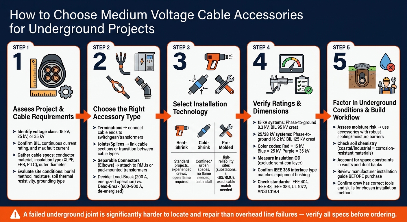
- Understand System Requirements: Identify your system's voltage class (15, 25, or 35 kV), current ratings, and fault current limits. Renewable energy systems often demand accessories that handle variable loads and thermal stress.
- Know Your Cable Specs: Gather details like conductor material, insulation type (e.g., XLPE, EPR), and dimensions (outer and insulation diameters). Ensure the accessory fits these parameters.
- Match Accessories to Function: Choose the right type - terminations for equipment connections, joints for cable linking, and separable connectors for easy disconnection or reconnection.
- Pick the Right Technology: Installation methods include heat-shrink, cold-shrink, and pre-molded options. Cold-shrink is ideal for confined spaces, while pre-molded offers precision for critical setups.
- Check Ratings and Standards: Verify voltage, insulation, and grounding compliance with U.S. standards like IEEE 48 and IEEE 386. Double-check dimensions and ensure compatibility with environmental factors like moisture and heat.
Selecting the right accessory ensures durability and reduces the risk of failures, which are harder to fix underground. Always prioritize proper installation and alignment with project-specific needs for long-term reliability.
How to Choose Medium Voltage Cable Accessories: 5-Step Selection Guide
Nexans Euromold - Introduction | Medium Voltage Power Cable Accessories

sbb-itb-501186b
Step 1: Assess Your Project and Cable Requirements
Before diving into product catalogs, take the time to clearly define your project needs. Skipping this step could lead to costly mistakes down the line.
Confirm System Design Parameters
Start by identifying your system's voltage class - commonly 15, 25, or 35 kV - and its phase-to-ground (U0) and line-to-line (U) ratings. Then, determine the Basic Insulation Level (BIL) needed to handle transient overvoltages. For example, a standard 200 A loadbreak connector is designed to handle fault currents up to 10 kA. Pushing beyond this limit could put your equipment at risk.
Also, verify the system's continuous current rating and the maximum fault current it can encounter. Systems connected to renewable energy sources, like solar or wind, often experience bidirectional or variable loads. These conditions can create more thermal stress on accessories compared to a steady utility feeder.
Once your system parameters are set, you can move on to gathering detailed cable specifications.
Gather Cable Specifications
Collect all relevant cable details, such as conductor size and material, insulation type (e.g., XLPE, EPR, or older PILC), shield design, and jacket material. These factors directly impact the compatibility of accessories. For instance, XLPE is widely used in modern U.S. underground systems due to its heat resistance, while EPR is valued for its flexibility and is often used in retrofit projects.
Pay close attention to the cable's outer diameter and insulation diameter, as they must fit within the accessory's specified range. If the cable exceeds the accessory's range-taking capacity, a splice may be necessary to step down the connection. As Eaton emphasizes in its installation guide:
"A tight fit helps keep moisture out and dielectric strength high."
Finally, evaluate the installation site conditions to ensure your chosen accessories can handle environmental and grounding requirements.
Review Installation Conditions and Grounding
Using the data collected about your system and cables, assess the specific conditions of your installation. Consider factors like whether the cables will be directly buried or installed in ducts, as well as the impact of moisture, heat, and space constraints. For example, high soil thermal resistivity can trap heat around the cable, increasing conductor temperatures. In such cases, accessories with higher thermal margins are essential.
Your grounding and bonding setup also plays a critical role in accessory selection. Whether you opt for single-point bonding, both-ends bonding, or cross-bonding will affect the level of heating in the cable screen and the accessory's rating requirements. Drain wires are crucial for preventing shield charge buildup. Additionally, confirm the earthing type and fault-clearing time early in the process. If faults take longer to clear, you may need to upgrade to a higher voltage class accessory to safely manage temporary overvoltages.
Step 2: Choose the Right Cable Accessory Type
Once you've nailed down your system parameters and cable specifications in Step 1, it's time to select the right accessory for each network point. Picking the wrong one - even if it matches the voltage rating - can lead to safety hazards or tricky maintenance issues later on.
Match Accessories to Network Function
The type of accessory you need depends on what that specific network point does. Here’s a quick breakdown:
- Terminations: These connect cable ends to equipment like switchgear, transformers, or busbars. They ensure both insulation continuity and environmental sealing.
- Joints (Splices): Used to link two cable sections, whether you're extending a cable run, fixing a break, or transitioning from older PILC (paper-insulated lead-covered) cable to newer XLPE (cross-linked polyethylene).
- Separable Connectors (Elbows): These submersible connectors are used to attach cables to devices like Ring Main Units (RMUs) or pad-mounted transformers.
Other options include junctions, which allow for sectionalizing circuits or creating lateral taps, and feed-throughs, which convert radial-feed equipment to loop-feed for testing, phasing, or grounding energized elbows. Standoff bushings are another handy choice, providing a safe spot to "park" an energized load-break elbow during maintenance.
"Cable terminations and joints form the weakest link in any distribution system, and a failed joint in an underground system is significantly more difficult to locate and repair than similar problems in overhead lines." - Ruiyang Group Northeast Cable Co., Ltd
Next, you’ll need to decide between a load-break or dead-break connection.
Dead-Break vs. Load-Break Connections
After selecting the right accessory type, figure out whether the connection will need to operate while energized. Here’s how the two options stack up:
| Feature | Load-Break Connector | Dead-Break Connector |
|---|---|---|
| Switching State | Operates while energized | Operates only when de-energized |
| Standard Amperage | 200 A | 600 A or 900 A |
| Operation Tool | Hotstick | Bolted connection tools |
| Common Applications | Pad‐mounted transformers, reclosers | Main feeders, riser poles |
| Fault Protection | Limited to a single fault-close event | Higher fault-close and BIL ratings |
Load-break connectors are perfect for situations like pad-mounted transformers or reclosers, where service continuity is critical. On the other hand, dead-break connectors are best for high-ampacity main feeders that need a solid, permanent connection.
Pro Tip: When using a load-break elbow, always operate it quickly. Slow movements can cause ionized gases to build up, which might lead to arcing and damage the contacts. For added flexibility, some 600 A dead-break T-bodies (like BT-TAP or T-OP II) include a 200 A load-break reducing tap plug, offering a hybrid solution.
Once you've settled on the connection type, the next step is choosing the right installation technology for your project.
Compare Accessory Installation Technologies
How you install the accessory can impact both the speed of the project and its long-term reliability. Here are the three main methods:
| Technology | How It Works | Best Fit Scenario |
|---|---|---|
| Heat-shrink | Shrinks onto the cable when exposed to heat | Ideal for standard projects with experienced crews where open flames are allowed |
| Cold-shrink | Pre-stretched elastomer contracts when a plastic core is removed | Great for confined spaces, urban settings, or quick restoration projects where open flames aren’t an option |
| Pre-molded | Factory-molded silicone or EPDM components slide onto the cable | Perfect for high-reliability setups like substations, GIS, or critical feeders needing precise stress management |
For underground urban projects, cold-shrink accessories shine. They eliminate the need for open flames in tight spaces like vaults and provide consistent radial pressure, reducing installation errors. Meanwhile, pre-molded accessories are a go-to for precision work in RMUs and GIS equipment, though they require exact cable dimension matching for optimal performance.
Step 3: Verify Ratings and Dimensions
Once you've selected the right accessory type and installation method, the next step is to double-check that all ratings and dimensions are properly aligned. Overlooking details like voltage class or cable diameter can lead to costly mistakes, especially in underground projects.
Check Voltage and Insulation Ratings
For 15 kV systems, accessories must meet specific requirements: a phase-to-ground rating of 8.3 kV and a BIL (Basic Insulation Level) of 95 kV crest. On the other hand, 25/28 kV systems require a phase-to-ground rating of 16.2 kV and a BIL of 125 kV crest. To simplify identification, many manufacturers, such as Eaton and Hubbell, use color-coded bushing nosepieces - red for 15 kV, blue for 25 kV, and purple for 35 kV.
Also, confirm that the IEEE 386 interface type matches the equipment bushing. For instance, Interface 5 is used for 15 kV 200 A systems, while Interface 7A is common for 25/28 kV systems. Matching these ensures a secure and shielded connection. Keep in mind that if your project site is above 6,000 feet in elevation, standard loadbreak devices should not be operated while energized.
The next step is to verify that the physical dimensions of the cable and accessory are compatible.
Confirm Cable Dimension Compatibility
When measuring the cable's insulation diameter, make sure to exclude the semi-con layer. Measuring over the semi-con can give you an inflated diameter, which could result in selecting an oversized housing. This mistake increases the risk of service failures. Once you’ve got the correct measurement, cross-check it against the housing code ranges provided by the accessory manufacturer. Additionally, confirm the conductor size (in AWG or kcmil) and determine the stranding type - whether it's compact, compressed, stranded, or solid - to ensure everything fits as intended.
"Cleanliness is paramount. Keep everything clean and make sure cutbacks are within the tolerances stated in the instructions." - Eaton
Confirm Compliance with U.S. Standards
Finally, ensure the accessories meet all applicable U.S. utility network standards. Key standards to verify include IEEE Std. 386 for separable connectors, IEEE Std. 592 for exposed semi-conducting shields, and ANSI Std. C119.4 for electrical connectors. For cables, check compliance with UL 1072, ICEA S-93-639, and AEIC CS-8, which cover shielded power cables up to 46 kV.
Additionally, confirm the insulation level - either 100% or 133%. For example, a 15 kV cable with 100% insulation uses 175 mils, while 133% insulation requires 220 mils. If the cables are for underground direct burial, review grounding requirements against NEC Article 305 and sections 311.36 and 250.4(A) to ensure proper code compliance.
Step 4: Factor In Underground and Installation Conditions
After confirming ratings and dimensions, it’s time to tackle the unique challenges that underground environments bring to accessory performance. Unlike above-ground installations, underground projects come with their own set of hurdles. Choosing the wrong accessory for the site can lead to failures that are much harder to identify and fix compared to overhead lines.
Assess Site Conditions
Moisture is the biggest threat. Water infiltration at insulation interfaces speeds up long-term deterioration, even if the circuit seems stable. For areas prone to flooding or high moisture levels, opt for accessories with robust sealing systems and moisture barriers. In regions with consistently high water tables, look for longitudinal water-blocking features to prevent water from migrating along the cable length.
Soil chemistry also plays a role. Coastal and industrial areas often expose metal components to salt, chemicals, and corrosive soils. In these cases, prioritize accessories with materials that resist corrosion and tracking. Additionally, underground chambers and dense cable trenches can trap heat, accelerating aging and reducing safety margins. To combat this, select accessories designed to handle high temperatures and maintain stable interface pressure during thermal cycles.
Once you’ve evaluated environmental factors, the next step is to consider the physical layout and installation methods to ensure compatibility with your project.
Account for Physical and Space Constraints
Physical installation limitations can be just as critical as environmental challenges. Underground vaults, older switchgear rooms, and retrofit projects often leave little room to maneuver. Before purchasing accessories, review their dimensions, bending requirements, and installation sequence. This prevents unexpected issues on-site that could lead to delays or extra costs.
"A technically strong accessory can still become a poor choice if the site does not allow safe preparation and assembly." - Site Editor, East Energy Electrical Engineering Co., Ltd. (4E)
When multiple circuits are installed in a shared trench or duct bank, mutual heating can reduce the system’s overall ampacity. For such scenarios, consider using thermal backfill to help dissipate heat away from joints and terminations, especially in areas with high soil thermal resistivity.
Match Installation Method to Crew Skills and Tools
Underground installations require techniques that account for spatial constraints and safety concerns. For example, heat-shrink methods involve open flames, which can be unsafe or even prohibited in confined spaces like vaults or near other utilities. In such cases, cold-shrink accessories are a safer alternative.
Make sure there’s enough clearance to slide and remove the cold-shrink support core during installation. On large-scale projects with multiple crews, cold-shrink also ensures more consistent results.
"Because the installation process is simpler and does not depend on the skill of operating a torch, results tend to be more uniform." - Haivo Electrical Co., Ltd.
Step 5: Build a Selection Workflow
By now, you've gathered all the necessary environmental, physical, and technical details. The next step is creating a workflow that ties all these factors together, ensuring no costly mistakes occur before you place your equipment order.
Record System and Cable Data
Start by documenting all the critical system parameters and cable details. This includes rated voltage (Uo/U/Um), grounding method, fault clearing time, conductor material, cross-sectional area, insulation type (such as XLPE, EPR, or PILC), and screen design. These details help define the voltage stress and installation needs.
Here's one common pitfall to avoid: always measure the outer diameter of the cable insulation, not the overall cable diameter. Haivo Electrical Co., Ltd. explains:
"The outer diameter of the cable insulation - not the overall cable diameter - is what matters for cold shrink tube selection."
Don’t forget to include site-specific conditions, like ambient temperature, soil thermal resistivity, moisture exposure, and any space limitations in vaults or duct banks.
Select Accessory Type and Installation Technology
Once your data is complete, match the accessory type to your network's requirements and the realities of your installation site. Start by identifying the network function - whether it’s a straight joint, termination, or separable connector. Then, choose an installation technology that aligns with the site conditions and your crew's expertise.
| Technology | Key Strength | Key Consideration | Best Fit |
|---|---|---|---|
| Heat Shrink | Broad application range | Requires skilled torch use and heating control | Standard projects with experienced crews |
| Cold Shrink | No heat source; faster, consistent | Precise insulation diameter matching is critical | Confined spaces, urban work, hazardous sites |
| Pre-molded | Stable geometry; stress control | Needs exact cable matching | High-reliability substations, GIS/RMU |
| Liquid Insulation | Excellent void filling and sealing | Demands strict process control | Applications prioritizing void elimination |
For ungrounded systems or networks with delayed fault clearing, consider upgrading to a higher Uo rating. For instance, on a 10 kV network, using an accessory rated at 8.7/15 kV ensures it can handle elevated phase-to-earth voltage during faults.
Verify Ratings and Installation Requirements Before Purchase
Before placing your order, double-check your selections against the data sheet. Confirm the accessory's continuous current rating, fault current limit (e.g., 200 A loadbreak connectors have a 10-kA fault current ceiling and are not overload-rated), and BIL (such as 95 kV for 15 kV systems). For cold shrink kits, ensure the cable insulation diameter falls within the kit's recovery range. A mismatch here can lead to insufficient interface pressure and a poor seal.
Also, review the manufacturer's installation guide before making the purchase. This ensures your crew has the necessary tools and skills, and that the site setup can accommodate the chosen installation method. Ruiyang Group Northeast Cable Co., Ltd. highlights the importance of this preparation:
"A failed joint in an underground system is significantly more difficult to locate and repair than similar problems in overhead lines."
Catching potential mismatches on paper is far less expensive - and much easier - than fixing them once the equipment is in place underground.
Conclusion: Key Points for Selecting Medium Voltage Cable Accessories
Choosing the right medium voltage cable accessories for underground projects hinges on understanding your system, aligning the accessory with its purpose, and double-checking every detail before making a purchase.
Start by reviewing your cable and system specifications as part of a final checklist. Reconfirm your system data and ensure the selected accessory is suited to its intended function and the specific site conditions. Once you've verified these details, make sure all components adhere to industry standards.
Pay special attention to compliance with U.S. standards such as IEEE 404 for joints, IEEE 48 for terminations, and UL 1072 for medium voltage cables. These standards aren't just bureaucratic hurdles - they define the performance benchmarks for normal loads, emergency overloads (up to 140°C), and short-circuit scenarios.
As 4E Energy emphasizes:
"Field reliability often reflects installation repeatability as much as material quality."
For a practical starting point, Electrical Trader offers a centralized online marketplace featuring a wide range of new and used medium voltage accessories that meet these standards. This resource can help you compare options against your verified project specifications.
FAQs
What’s the fastest way to confirm an MV accessory will fit my cable?
To ensure an accessory is compatible with your cable, compare its technical data with the cable's specifications. Pay close attention to details like conductor size, insulation type, screen design, and voltage class. Avoid trusting general labels alone - minor mismatches can interfere with the electric field or lead to sealing problems. For underground projects, platforms like Electrical Trader provide a marketplace to source the electrical components you need.
When should I use load-break vs. dead-break connectors underground?
When connecting or disconnecting cables in an energized system, load-break connectors are the go-to option. These are typically used in applications like reclosers, switchgear, or mobile transformers. On the other hand, dead-break connectors are designed for high-voltage systems that require complete de-energization before disconnection. They provide greater ampacity and enhanced fault protection, making them a reliable choice for riser poles, sectionalizing cabinets, and main feeder circuits where dependable performance is essential.
Which is better for underground work: heat-shrink, cold-shrink, or pre-molded?
The best option comes down to your project’s specific requirements, budget, and working conditions. Cold-shrink is a strong contender for underground applications because it provides consistent radial pressure, conforms to irregular surfaces, and doesn’t require open flames during installation. Heat-shrink, on the other hand, is more budget-friendly but needs an open flame for installation and doesn’t maintain dynamic pressure. Pre-molded accessories stand out for their precision fit and long-lasting performance, though they come at a higher cost. No matter which type you choose, ensuring proper installation is critical to avoid failures.