
Load Balancing vs Power Factor Correction
Load balancing and power factor correction solve different electrical problems but can work together to improve system efficiency.
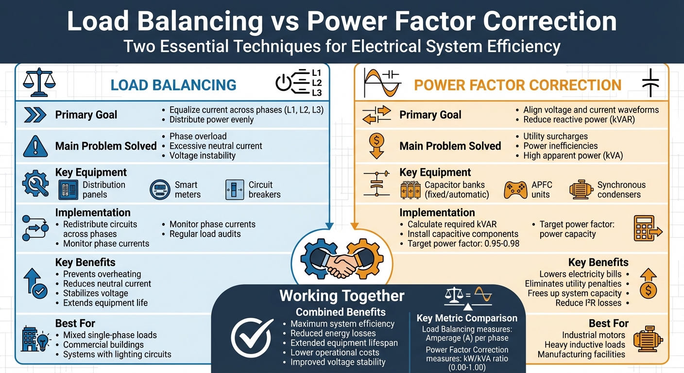
- Load balancing ensures even power distribution across three-phase systems, reducing risks like overheating and voltage instability.
- Power factor correction aligns voltage and current, cutting reactive power and avoiding utility penalties.
Key differences:
- Load balancing addresses phase imbalances using tools like distribution panels and smart meters.
- Power factor correction uses capacitors or advanced systems to improve power usage.
Both methods extend equipment life, reduce energy losses, and prevent costly issues. Combining them creates a safer, more efficient electrical system.
Quick Comparison:
| Feature | Load Balancing | Power Factor Correction |
|---|---|---|
| Goal | Equalize current across phases | Reduce reactive power (kVAR) |
| Main Issue Solved | Phase overload, neutral current issues | Utility surcharges, inefficiencies |
| Equipment | Distribution panels, smart meters | Capacitor banks, APFC units |
| Key Benefit | Prevents overheating, stabilizes voltage | Lowers bills, boosts power efficiency |
This guide explains how each method works, their benefits, and how to implement them effectively.
Load Balancing vs Power Factor Correction: Key Differences and Benefits
What is Load Balancing?
Definition and Purpose
Load balancing plays a crucial role in managing electrical systems, especially when compared to power factor correction strategies. At its core, load balancing ensures that electrical demand is evenly distributed across the three conductors (or phases) of a three-phase power system. These phases - commonly labeled L1, L2, and L3 in the United States, and identified by Brown, Black, and Grey color codes in the United Kingdom - operate with a 120° phase shift between them.
A properly balanced system reduces the risks associated with phase imbalances, such as overheating, voltage instability, and potential equipment damage. These imbalances often stem from uneven single-phase load connections, like those found in lighting circuits, office devices, or small appliances. Adding new equipment without considering phase distribution can also lead to problems. In a three-phase four-wire system, an imbalance can cause the neutral conductor to carry excessive current, which might even surpass the current in the individual line conductors.
Understanding how load balancing works in practice helps to illustrate its importance.
How Load Balancing Works
The process begins with a load survey, typically conducted using a power quality analyzer to measure the current draw at critical points in the system. Electricians then distribute circuits as evenly as possible - for example, assigning 10 circuits per phase in a setup with 30 lighting circuits. Clear labeling of circuits is essential for troubleshooting and making adjustments when usage patterns change.
While three-phase systems are common in industrial and commercial settings due to their efficiency (they require less conductor material to deliver the same power as single-phase systems), achieving perfect balance is challenging. This is largely because single-phase loads fluctuate over time. Regular audits are key to identifying imbalances caused by seasonal changes, the addition of new equipment, or system faults.
These steps lay the groundwork for the advantages outlined below.
Benefits of Load Balancing
Balanced electrical loads bring several advantages to a system. They help optimize power capacity and reduce energy losses, ensuring consistent voltage levels across all phases. This consistency prevents issues caused by overburdened phases. Additionally, reducing the current in the neutral conductor lowers the risk of conductor overheating, which enhances overall system safety.
Another benefit is the extended lifespan of equipment. By reducing mechanical and thermal stress on components like transformers, generators, and motors, balanced loads contribute to more reliable operations.
"Balancing electrical loads across three phases is both an art and a science, requiring careful planning, monitoring, and a proactive approach to maintenance and system design".
The increasing adoption of distributed energy resources, such as solar photovoltaic systems, further underscores the importance of load balancing. Technologies like smart meters and real-time monitoring are becoming essential tools for maintaining system stability in these scenarios.
While load balancing focuses on addressing phase imbalances, it works hand-in-hand with power factor correction, which deals with reactive power issues - a subject we'll explore next.
sbb-itb-501186b
What is Power Factor Correction?
Definition and Purpose
Power factor correction (PFC) is all about aligning voltage and current to boost real power output. This is done by introducing a leading reactive component (capacitive kVAR) to counteract the lag caused by inductive loads.
The power factor itself is the ratio of real power (measured in kW) to apparent power (measured in kVA). When the power factor is low - often due to multiple induction motors - it can lead to utility penalties. Engineers typically calculate the required correction using this formula:
kVAR required = kW × (tan θ₁ − tan θ₂)
Here, θ₁ is the angle corresponding to the current power factor, while θ₂ is the angle for the desired power factor.
"The IEEE defines power factor in IEEE Std 1459-2010 as the ratio of active power to apparent power, a definition that frames PFC as fundamentally an efficiency and capacity issue rather than merely an equipment concern." - IEEE
Let’s explore the methods used to achieve PFC.
Methods of Power Factor Correction
There are several approaches to PFC, each suited to specific load conditions:
- Fixed Capacitor Banks: These provide a constant level of capacitance and are controlled manually or via contactors. They work best for steady loads like large motors or transformers.
- Automatic Capacitor Banks: For facilities with varying loads, these systems use power factor relays to switch capacitor stages (typically 6 to 12 steps). This prevents over-correction when demand drops.
In cases where harmonic distortion is a concern - such as in data centers or facilities with variable frequency drives - active power factor correction (APFC) comes into play. APFC systems use power electronics to inject reactive current in real time, countering distortion. If total harmonic distortion (THD) exceeds 5% at the point of common coupling, harmonic detuning reactors are recommended alongside capacitor banks.
Before specifying equipment, a load survey and harmonic analysis using a power quality analyzer are essential. High harmonic environments can lead to premature capacitor failure, so proper assessment is critical. Keep in mind that automatic switched capacitor banks typically cost 1.5 to 2 times more than fixed capacitor systems.
Benefits of Power Factor Correction
PFC offers clear and measurable advantages. For starters, it can lower electricity bills by eliminating utility surcharges and demand penalties. It also frees up capacity in existing transformers, switchgear, and feeder conductors - often avoiding the need for expensive upgrades. Additionally, reduced current draw minimizes resistive (I²R) losses and thermal loading, ensuring cooler, more efficient operation.
On top of that, less heat-related stress extends the lifespan of motors, cables, and transformers. Improved voltage stability benefits sensitive equipment and long cable runs, while compliance with power quality standards like IEEE 519-2022 ensures harmonic distortion stays within acceptable limits.
However, experts caution against correcting power factor beyond 0.98 lagging. Overcorrection can lead to voltage rises and potential equipment misoperation. To maximize results, correction can be applied at individual motor terminals for localized benefits or at the main bus for cost-effective compliance with utility requirements. All installations should adhere to NFPA 70 (National Electrical Code) Articles 460 and 430, while capacitor discharge paths must be examined for arc flash protection as outlined in NFPA 70E.
Load Balancing on 3 Phase 480V Systems Explained
Main Differences Between Load Balancing and Power Factor Correction
This section breaks down how load balancing and power factor correction differ in their objectives, methods, and practical advantages.
Purpose
Load balancing and power factor correction tackle distinct electrical issues. The goal of load balancing is to even out the current across all three phases (A, B, and C) in a power system. When currents are unbalanced, it can lead to voltage fluctuations and the creation of negative sequence currents. These currents don’t contribute to useful work but instead cause motors and generators to wear out more quickly.
On the other hand, power factor correction focuses on aligning the voltage and current waveforms more closely. This reduces reactive power (kVAR) and ensures that the apparent power (kVA) drawn from the grid is closer to the real power (kW) used. This is especially important for commercial customers who might face penalties if their power factor drops below a certain threshold, usually between 0.85 and 0.95 lagging.
Next, let’s explore the methods each approach uses to achieve these goals.
Methods Used
Load balancing involves redistributing single-phase loads across the three phases and managing neutral currents to create symmetry.
Power factor correction uses tools like capacitors or synchronous condensers to counteract inductive lag. Capacitor banks - either fixed or automatic - store energy and supply leading reactive power to balance out the inductive effects of motors and transformers. In more complex setups, such as those involving variable frequency drives or high harmonic distortion, active power factor correction (PFC) systems use power electronics to inject reactive current as needed. Synchronous condensers, which are over-excited synchronous motors running without a load, provide precise control over reactive power.
These distinct methods cater to different needs, leading to varied applications and outcomes.
Applications and Benefits
Each technique shines in specific scenarios. Load balancing is ideal for systems with significant single-phase loads, such as mixed-use setups. This approach helps to avoid overheating equipment and stabilizes phase-to-neutral voltages.
Power factor correction is critical for operations with heavy inductive loads, such as manufacturing facilities with numerous motors, HVAC systems, or large transformers. The benefits include avoiding utility surcharges, freeing up capacity in existing equipment, and lowering resistive losses. For example, improving the power factor from 0.6 to unity in a 60 kW system can reduce annual energy demand from 365,000 units to 219,000 units. Additionally, it can increase the capacity of transformers and switchgear without the need for expensive upgrades.
| Feature | Load Balancing | Power Factor Correction |
|---|---|---|
| Primary Goal | Equalize current magnitude across phases A, B, and C | Reduce reactive power (kVAR) |
| Main Equipment | Phase redistribution and neutral current compensators | Capacitor banks, synchronous condensers, APFC |
| Key Benefit | Prevents negative sequence heating in motors | Eliminates utility penalties and reduces kVA demand |
| Best Application | Mixed single-phase loads on three-phase systems | Large induction motor and transformer loads |
How Load Balancing and Power Factor Correction Work Together
Combined Effects
When it comes to improving electrical system performance, load balancing and power factor correction work hand in hand to achieve better efficiency. Together, they tackle two critical issues: distributing current evenly across phases and aligning the current with voltage to reduce reactive power. This combination results in a system where currents are balanced and more closely aligned with their respective phase voltages.
Here’s why this matters: balancing the load prevents overheating in individual phases and reduces neutral currents, while power factor correction minimizes the overall current demand by addressing reactive power. This dual strategy helps cut down on resistive losses (I²R) and reduces thermal stress on key components like transformers, motors, and generators.
Another benefit? Voltage stability. By ensuring phases aren’t overloaded and reducing the reactive demand on equipment, the system experiences fewer voltage drops. It also reduces negative sequence currents - those pesky currents that don’t contribute to work but instead cause internal heating in inductive devices. The outcome is extended equipment life and fewer breakdowns.
Real Examples of Using Both Techniques
The advantages of combining these techniques are evident across different industries and applications.
Industrial Plants: Many industrial plants rely on induction motors, which can drag the power factor down to 0.70–0.75 when running at partial loads. By implementing power factor correction directly at motor terminals, these plants can reduce the strain on feeders. Meanwhile, balancing auxiliary single-phase loads at the main distribution board prevents overheating in specific phases. This dual approach not only avoids utility penalties for poor power factor but also minimizes the risk of equipment damage due to phase imbalances.
Data Centers: Data centers present unique challenges. Switch-mode power supplies in servers create significant harmonic distortion, demanding active power factor correction to manage non-linear loads. At the same time, server racks must be balanced across phases to maintain the efficiency of uninterruptible power supply (UPS) systems. Without these measures, capacitors can overheat due to harmonics, and unbalanced loads can hurt UPS performance. Given that IEEE 519-2022 limits total harmonic distortion to 5% at the point of common coupling, failing to address these issues can lead to costly inefficiencies and equipment failures.
Commercial HVAC Systems: Large induction motors in HVAC chillers often lower the power factor, while uneven loads from lighting and office equipment create phase imbalances. These problems can trigger utility penalties, such as "demand ratchet" clauses, which lock in higher billing rates based on peak demand periods. To combat this, automatic switched capacitor banks can be installed to correct the power factor on motor loads, while redistributing lighting circuits across phases ensures a more balanced system. The result? Lower utility costs and smoother operations.
Comparison Table: Load Balancing vs Power Factor Correction
Below is a side-by-side comparison highlighting the differences in purpose, approach, and equipment between load balancing and power factor correction:
| Feature | Load Balancing | Power Factor Correction |
|---|---|---|
| Primary Goal | Distribute current evenly across three phases (L1, L2, L3) | Synchronize voltage and current waveforms |
| Target Issue | Phase overload and excessive neutral current | Reactive power (kVAR) inefficiencies and utility surcharges |
| Common Causes | Uneven distribution of single-phase loads | Inductive loads such as motors, transformers, and lighting ballasts |
| Key Metric | Amperage (A) per phase and neutral current levels | Power factor: ratio of real power (kW) to apparent power (kVA) |
| Key Equipment | Distribution panels, smart meters, circuit breakers | Capacitor banks, Automatic Power Factor Correction (APFC) units, synchronous condensers |
| Implementation Method | Redistributing circuits and optimizing system design | Adding capacitive components to offset inductive loads |
| Key Benefit | Decreases neutral current and reduces stress on equipment | Cuts demand charges and boosts system efficiency |
| System Impact | Enhances voltage stability across phases | Frees up system capacity (kVA) for additional loads |
This comparison underscores how each method addresses specific electrical challenges. Load balancing focuses on redistributing current to prevent phase overloads and neutral conductor overheating, while power factor correction improves the efficiency of power usage by aligning voltage and current.
One critical safety concern load balancing tackles is the risk of excessive neutral current, which can overheat conductors and transformers. Meanwhile, power factor correction often involves higher upfront costs due to automatic capacitor banks, which are designed to avoid over-correction during periods of low load. On the other hand, load balancing typically relies more on labor-intensive circuit adjustments and monitoring systems like smart meters.
Both techniques often work hand-in-hand to optimize electrical systems. Next, we'll delve into how these methods are applied in real-world scenarios.
How to Implement These Techniques
Building on the ideas of load balancing and power factor correction, here are practical steps to help you put these methods into action.
Choosing the Right Equipment
Start by using a power quality analyzer to measure your system's power factor and total harmonic distortion (THD) at key points. This data serves as a foundation for selecting the right equipment and determining the best installation locations.
- For stable loads, fixed capacitor banks are a solid choice.
- For variable loads, automatic capacitor banks are better since they can adjust dynamically. These units use a power factor relay to manage multiple capacitor stages, avoiding over-correction during periods of low load. Keep in mind that automatic units typically cost about 1.5–2 times more than fixed options.
- For non-linear loads (like variable frequency drives or uninterruptible power supplies), a harmonic analysis is essential. If THD at the point of common coupling exceeds 5%, consider using harmonic detuning reactors with fixed capacitor banks or active power factor correction units.
When it comes to load balancing, tools like distribution panels, circuit breakers, and smart meters can monitor phase imbalances in real time, helping you address any issues.
Once the equipment is selected, use the calculation guidelines below to configure your system.
Calculation and Setup Guidelines
After choosing your equipment, calculate the necessary correction values using this formula:
kVAR required = kW × (tan θ₁ − tan θ₂)
Here, θ₁ is your current power factor angle, and θ₂ represents your target angle. In the U.S., utility companies often impose penalties if your power factor drops below 0.85 to 0.95 lagging. Aiming for a target between 0.95 and 0.98 lagging is a good practice. However, correcting beyond 0.98 can lead to issues like voltage rise and relay misoperation, so it’s best to avoid overcorrection.
Placement matters. Installing capacitors at individual motor terminals can relieve feeder loads but requires more units and higher labor costs. On the other hand, bulk correction at the main service entrance or bus is generally more cost-effective, though it won’t reduce the load on internal feeder conductors.
For load balancing, plan your distribution carefully. Spread single-phase circuits - such as those for lighting, outlets, and small devices - across phases L1, L2, and L3. Clear labeling of circuits makes it easier to adjust loads and maintain a balanced neutral.
Regular monitoring is essential to keep your system performing well. Conduct inspections and load measurements frequently to spot changes caused by new equipment or seasonal demand shifts. Also, ensure compliance with NEC Article 460 (for capacitors), Article 430 (for motors), and address capacitor discharge paths in arc flash studies per NFPA 70E.
For products to support these implementations, resources like Electrical Trader offer a variety of options.
Conclusion
Load balancing and power factor correction are two essential techniques that work together to improve electrical system efficiency. Load balancing ensures that current is evenly distributed across all three phases, preventing issues like neutral overload and hotspots. On the other hand, power factor correction minimizes reactive power, reducing overall current demand and helping avoid utility penalties. While these methods rely on different mechanisms, their combined use creates a more efficient and reliable system.
Each technique addresses specific challenges, and overlooking one can negatively impact overall performance. For instance, even with an excellent power factor, phase imbalances can lead to neutral currents exceeding line currents. Both methods can lead to substantial financial and operational benefits. Power factor correction alone can save facilities anywhere from hundreds to tens of thousands of dollars annually, depending on their size. Meanwhile, load balancing reduces I²R losses and extends the lifespan of equipment. Together, these strategies maximize the capacity of existing transformers and switchgear, potentially eliminating the need for expensive upgrades.
The next step is practical implementation. Start by using a power quality analyzer to assess your system. Then, calculate the necessary corrections and evenly distribute single-phase loads across L1, L2, and L3. Regular monitoring is crucial to adjust for changes, such as new equipment or shifting demand.
Finally, selecting the right equipment is key to success. Whether you need capacitor banks, distribution panels, or smart meters, platforms like Electrical Trader (https://electricaltrader.com) provide a variety of new and used components to suit your project needs.
FAQs
How can I tell if I have a load imbalance or a low power factor?
A load imbalance happens when electrical load isn't evenly spread across the three phases of a system. You can usually spot this by keeping an eye on phase currents and voltages.
On the other hand, a low power factor is tied to excessive reactive power, which can be measured with specialized meters. Common signs include inefficient energy use or unexpectedly high electricity bills.
Both issues demand unique approaches to ensure the system runs efficiently.
Should I fix load balancing before adding capacitor banks?
Addressing load balancing should typically be your first priority. Why? Because it ensures that your system operates efficiently, reduces voltage imbalances, and minimizes wear and tear on your equipment. Plus, when it comes to sizing capacitor banks for power factor correction, a stable and balanced load is crucial. Without it, you risk problems like overcorrection or even harmonic resonance. By fixing load imbalances first, you set the stage for power factor correction to work as intended.
Will power factor correction lower my electric bill if I’m not penalized?
Power factor correction (PFC) boosts the efficiency of power delivery by cutting down on reactive power and reducing system losses. If your utility provider doesn’t charge penalties for a low power factor, PFC might not lead to an immediate drop in your energy bill. That said, it can still help reduce energy waste and decrease equipment overheating, which could lower operational costs in the long run. Even without direct savings, improving system efficiency remains a major advantage.


