Instrument Transformers: Types and Uses
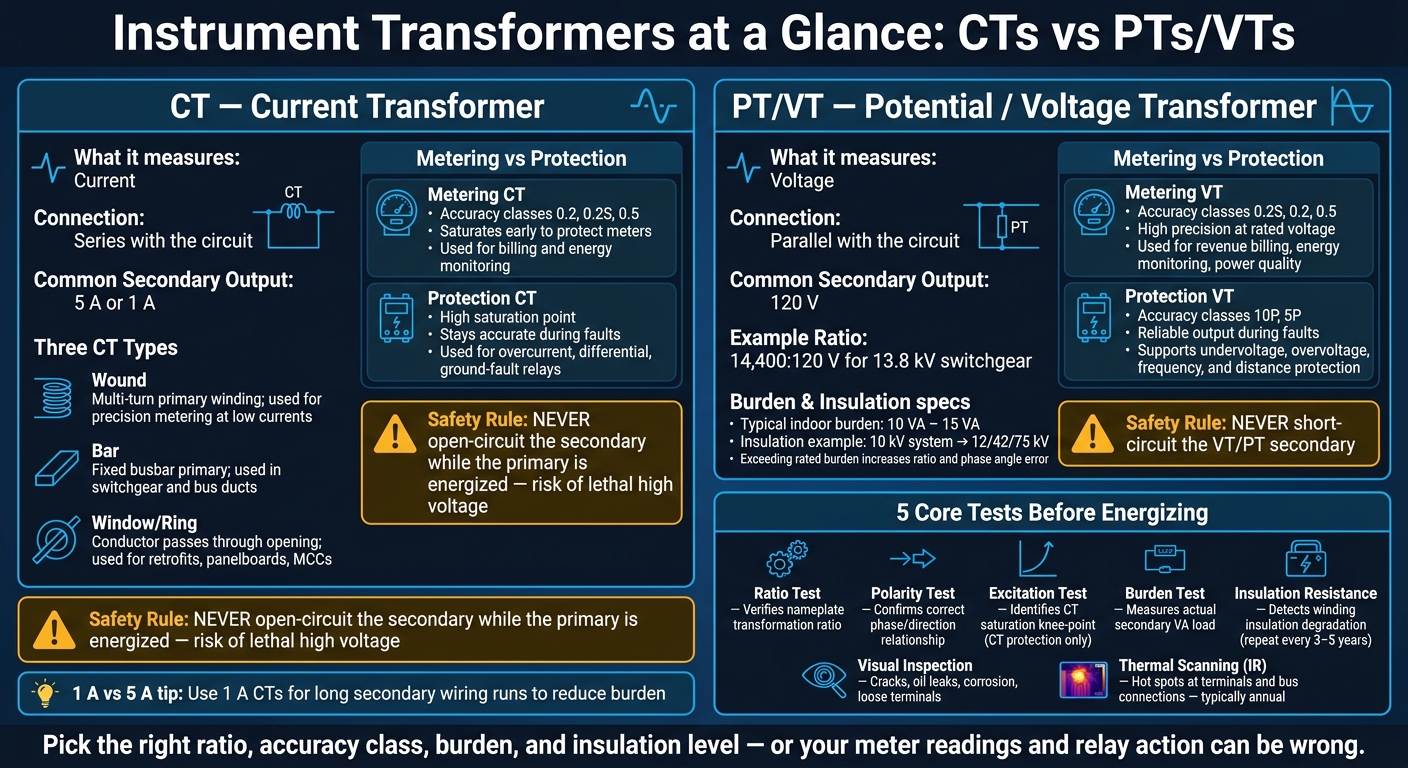
If you work with medium- or high-voltage power, you can’t hook meters and relays straight to the line. You need CTs to step current down to 5 A or 1 A, and PTs/VTs to step voltage down to 120 V so connected devices can read the system without being exposed to line voltage or fault current.
Here’s the short version:
- CTs measure current and are used in switchgear, feeders, MCCs, and service gear.
- PTs/VTs measure voltage and are common in substations and service entrances.
- Metering units focus on tight accuracy at normal load.
- Protection units must stay usable during faults so relays can trip on time.
- CT secondary circuits must never be left open when the primary is energized.
- VT/PT secondary circuits must never be shorted.
- Common checks include ratio, polarity, burden, excitation, and insulation resistance tests.
- For long secondary runs, 1 A CTs are often used because they reduce burden.
- Typical U.S. systems covered here are 60 Hz and use standard secondaries like 5 A, 1 A, and 120 V.
If I had to reduce the whole topic to one line, it would be this: pick the right ratio, accuracy class, burden, and insulation level - or your meter readings and relay action can be wrong.
CT vs PT/VT: Instrument Transformer Types, Specs & Safety Rules
Understanding CTs and PTs: The Complete Guide to Instrument Transformers
sbb-itb-501186b
Quick comparison
| Device | What it measures | Common secondary | Connection | Main use |
|---|---|---|---|---|
| CT | Current | 5 A or 1 A | Series | Metering and protection |
| PT / VT | Voltage | 120 V | Parallel | Metering, relays, monitoring |
The rest of the article explains the main CT types, the split between metering and protection units, where these transformers are used, and what to test before putting them into service.
Current Transformers: Types, Ratings, and Common Uses
CTs step line current down to a standard 5 A or 1 A secondary for meters and relays. If the secondary wiring run is long, 1 A CTs are often the better pick because they cut burden. The way a CT is built also affects where it can be installed and how it behaves in service.
CT Types: Wound, Bar, and Window
Wound primary CTs have a multi-turn primary winding built into the unit. That makes them a good fit for precision metering at lower currents.
Bar-type CTs use a fixed internal busbar as the primary conductor. You’ll often see them built into switchgear and bus ducts.
Window (ring) CTs don’t have a primary winding at all. Instead, the existing cable or busbar passes through the opening. That makes them a practical option for retrofits, panelboards, and motor control centers.
| CT Type | Construction | Typical Current Range | Common Installation Point | Typical Use |
|---|---|---|---|---|
| Wound | Multi-turn primary winding built into the CT | Low current | Indoor control panels | Precision metering |
| Bar | Single fixed busbar as primary | Medium to high | Switchgear, bus ducts | Feeder monitoring, main service entrances |
| Window (Ring) | Conductor passes through the window | High current | Panelboards, MCCs, bus ducts | Retrofits, general metering and protection |
Metering CTs vs. Protection CTs
Metering CTs are built for high accuracy at rated current. Common accuracy classes include 0.2, 0.2S, and 0.5. They saturate sooner, which helps protect meters.
Protection CTs are made to stay accurate at high multiples of rated current. In plain terms, they keep feeding relays a usable signal during fault conditions, so the relay can detect the problem and trip the circuit the right way.
| Feature | Metering CTs | Protection CTs |
|---|---|---|
| Primary Purpose | Revenue billing and load monitoring | Fault detection and equipment protection |
| Accuracy Focus | High accuracy at rated current | Accuracy during high fault currents |
| Saturation Behavior | Saturates early to protect delicate meters | High saturation point to maintain signal during faults |
| Common Applications | Utility billing, energy management systems | Overcurrent, differential, and ground-fault relays |
CT Safety and Installation Basics
Never open-circuit the secondary while the primary is energized. That’s not a minor mistake. An open secondary can generate extremely high voltage, creating a lethal shock risk and possibly damaging insulation.
Polarity also matters. Follow the markings on the CT:
- P1/P2 on the primary
- S1/S2 on the secondary
You should also ground one terminal of the CT secondary circuit. That helps keep the secondary wiring from reaching a dangerous voltage if the primary insulation fails.
Before commissioning, check ratio, polarity, grounding, and burden.
Voltage measurement uses PTs/VTs, covered next.
Voltage and Potential Transformers: Designs and Applications
Voltage Transformers (VTs) - also called Potential Transformers (PTs) - are used to measure voltage. Unlike a CT, which goes in series, a VT/PT connects in parallel with the circuit being monitored. That setup lets it read line voltage without cutting into the circuit. It also steps system voltage down to standard secondary levels for relays, meters, and control devices. The same ratio-and-isolation idea applies whether the unit is used for metering or relaying.
Unlike CTs, VT secondaries should never be short-circuited.
Single-Phase and Three-Phase PT/VT Arrangements
Single-phase VTs are often used for phase-to-ground or phase-to-phase measurement. In substations and switchgear lineups, engineers often use several single-phase units together to cover all phases in a three-phase system. Indoor and outdoor units use insulation designs that fit the conditions where they’ll operate.
Accuracy, Burden, and Insulation Requirements
VT selection usually comes down to three main specs: accuracy class, burden, and insulation level.
Accuracy class works much like it does with CTs. Classes 0.2S, 0.2, and 0.5 are common in revenue metering and energy monitoring, while 10P and 5P are used for protection relaying.
Burden is the total load the VT secondary has to supply, measured in volt-amperes (VA). Common indoor ratings are 10 VA and 15 VA. If the connected load goes past the rated burden, accuracy drops. And that can mean metering errors or relay problems.
Insulation level has to match system voltage, with extra margin for surges. For example, a VT on a 10 kV system might have a rated insulation level of 12/42/75 kV.
How PTs/VTs Are Used in Metering and Relaying
In metering, VTs provide the voltage signal needed for accurate electric energy measurement and billing. They also help with power quality checks and synchronization checks.
In protection schemes, VTs give relays the voltage reference they need to detect abnormal conditions. Those inputs support undervoltage, overvoltage, frequency monitoring, and distance protection functions.
The table below shows how VT requirements differ between metering and protection applications.
| Feature | Metering | Protection/Relaying |
|---|---|---|
| Common Accuracy Classes | 0.2S, 0.2, 0.5 | 10P, 5P |
| Primary Goal | Revenue billing, energy monitoring | Fault detection, relay tripping |
| Key Performance Focus | High precision at rated voltage | Reliable output during fault conditions |
| Typical Burden | 10 VA – 15 VA | Varies by relay type and quantity |
How to Select, Test, and Maintain Instrument Transformers
Once you've picked the right CT or PT/VT type, the next job is simple in theory and easy to get wrong in practice: match it to the system, then verify it before energizing.
Selection Criteria for Procurement and System Matching
The main choices from earlier - ratio, burden, accuracy, and insulation - turn straight into procurement specs. At a minimum, gather:
- primary rating
- secondary rating
- ratio
- accuracy class
- burden in VA
- insulation level
- mounting style
- whether the unit will be installed indoors or outdoors
For a 480 V feeder with a maximum continuous load of about 500 A, a 600:5 CT is a common pick. For medium-voltage switchgear at 13.8 kV, a PT with a 14,400:120 V ratio steps voltage down to the standard 120 V input that most meters and relays expect. Then program the meter or relay to the exact nameplate ratio and tap setting. Close isn't good enough here.
Accuracy class should match the job. A metering circuit and a protection circuit don't ask for the same thing. Also, keep total secondary burden below the rated VA. If you go past the rated burden, ratio error and phase angle error both increase.
Insulation class also needs to match the system voltage and the install environment.
After purchase, commissioning tests confirm that the unit matches the nameplate and that the installation was done right.
Commissioning and Maintenance Tests
Before energizing a new CT or PT/VT installation, five core tests should be done.
- A ratio test confirms the actual transformation ratio.
- A polarity test confirms the phase relationship between primary and secondary terminals.
- An excitation test shows the CT knee point and saturation behavior.
- A burden test measures the actual VA load on the secondary circuit.
- Insulation resistance testing checks that winding-to-winding and winding-to-ground insulation is intact for the transformer's voltage class.
After commissioning, routine checks help spot drift, damage, and loose terminations before they turn into bigger problems. Visual inspections can catch cracked or discolored insulation, oil leaks on fluid-filled units, corrosion, and loose terminal connections. Infrared thermal scanning during normal energized operation helps find hot spots at terminals and bus connections without taking equipment offline. Many facilities run these scans once a year or fold them into condition-based maintenance rounds.
Insulation resistance tests are often repeated every 3 to 5 years in industrial plants, and more often in harsh environments. Ratio and polarity checks are also worth repeating after any major system change, relay upgrade, or unexplained metering issue.
| Test Type | Purpose | Applied To | Commissioning or Maintenance |
|---|---|---|---|
| Ratio Test | Verifies nameplate transformation ratio | CT & PT/VT | Commissioning |
| Polarity Test | Confirms correct phase/direction relationship | CT & PT/VT | Commissioning |
| Excitation Test | Identifies CT saturation knee-point | CT (Protection) | Commissioning |
| Burden Test | Measures actual secondary circuit VA load | CT & PT/VT | Commissioning |
| Insulation Resistance | Detects winding insulation degradation | CT & PT/VT | Both |
| Visual Inspection | Finds cracks, leaks, loose connections | CT & PT/VT | Routine Maintenance |
| Thermal Scanning | Locates hot spots and high-resistance joints | CT & PT/VT | Routine Maintenance |
When sourcing used or surplus instrument transformers - whether through a distributor or an online marketplace like Electrical Trader - ask for recent test reports that cover ratio, insulation resistance, and visual or thermal inspection results before you commit to a purchase. That paperwork is the acceptance check, not a separate buying consideration.
Sourcing Instrument Transformers and Final Takeaways
Using Specifications to Find the Right CT or PT/VT
Once a unit passes commissioning, sourcing turns into a spec-matching job. The nameplate should be your procurement checklist.
Start with the application: metering or protection, indoor or outdoor. Then line up the ratio, accuracy class, burden, insulation level, and mounting style. That makes it much easier to sort through inventory and find a close match fast. Electrical Trader lets you filter listings by voltage, rating, and category to match a specific CT or PT/VT to your project requirements.
For any used unit, ask for maintenance records and ratio test results before you commit to a purchase.
Conclusion: Key Points to Remember
With sourcing narrowed to the right specs, the main point is simple: CTs step down current, and PTs/VTs step down voltage. Metering calls for high-accuracy classes. Protection calls for classes made for fault conditions. Getting the specs right during procurement, installation, and commissioning is what drives performance.
FAQs
How do I choose the right CT ratio?
Choose a current transformer (CT) ratio with a primary rating that matches the highest current in the circuit you want to monitor. A CT steps high primary current down to a standard secondary output, usually 1 A or 5 A, so measuring instruments and protective relays can use it safely.
You should also check that the accuracy class and burden rating fit your application. That helps avoid overheating and keeps measurements accurate.
When should I use a 1 A CT instead of 5 A?
Use a 1 A CT instead of a 5 A CT when the distance between the transformer and the meter or relay is long. The lower secondary current helps cut power loss and voltage drop in the secondary wiring, which matters a lot over long cable runs.
Also, make sure your protection relays and metering devices match the CT’s secondary output rating.
What happens if CT or VT burden is too high?
If the burden on a current transformer (CT) or voltage transformer (VT) goes past its rated capacity, it can’t reproduce the signal with good accuracy.
For CTs, staying within the rated burden helps keep measurements accurate and can help prevent overheating. Check that the total volt-ampere load from all connected devices stays at or below the transformer’s rated capacity.