Instrument Transformers: Types and Applications
Instrument transformers are crucial for safely measuring and monitoring electrical systems by scaling down high voltages and currents to manageable levels. These devices protect equipment and operators while ensuring accurate data for metering and protection. The two main types are:
- Current Transformers (CTs): Reduce high currents to standard levels (1A or 5A) for metering and protection.
- Voltage Transformers (VTs/PTs): Step down high voltages (e.g., 13.8 kV to 120V) for easier handling and monitoring.
- Capacitive Voltage Transformers (CCVTs): Handle extra-high-voltage systems (above 115 kV) and also support power line communication.
Each type has specific designs and applications, such as CTs for overcurrent protection in substations or VTs in data centers for voltage stability. Modern advancements like digital and optical transformers offer improved precision and safety, making them ideal for smart grids and high-demand systems.
Understanding specifications like accuracy class, burden ratings, and safety features is key to selecting the right transformer for your needs. Reliable platforms like Electrical Trader can simplify sourcing transformers that meet international standards.
Current Transformers (CTs)
How Current Transformers Work
Current transformers (CTs) rely on Faraday's Law of electromagnetic induction to function. When alternating current flows through the primary winding, which is connected in series with the circuit, it generates a magnetic field. This field induces a proportional current in the secondary winding. CTs step down high primary currents to a lower, standardized level (usually 1 A or 5 A), making it safe for measuring instruments and protective relays to handle currents that would otherwise be too dangerous to measure directly.
The secondary winding operates in a near short-circuit state due to its low impedance. This design is crucial for safety - if the secondary circuit is opened while the primary is energized, it can result in dangerously high voltage spikes. These spikes could damage insulation and pose serious shock hazards.
CTs come in various designs to suit different needs:
- Wound-type CTs: Feature two windings on a steel core.
- Bar-type CTs: Use a single busbar as the primary winding.
- Toroidal CTs: Allow a conductor to pass through the core opening, making installation straightforward.
- Bushing CTs: Encircle high-voltage bushings in equipment like generators or circuit breakers.
- Gas-insulated or oil-filled CTs: Are designed for harsh environments, offering added protection.
Where Current Transformers Are Used
Thanks to their ability to scale down high currents, CTs are indispensable for both measurement and protection purposes. In metering applications, CTs reduce high currents to standardized levels, enabling precise electricity metering and accurate utility billing. For protective relaying, they provide critical data to identify faults and monitor overcurrent situations, helping to prevent equipment failures.
CTs are widely used in:
- Electrical substations and high-voltage grids
- Switchgear or bushing installations
- Industrial facilities, where they monitor power usage and manage real-time load conditions
To maintain accuracy and prevent overheating, the load connected to the CT's secondary circuit (known as the burden) must stay within its rated capacity. Standard CTs typically have power ratings between 100 VA and 500 VA. Portable CTs, often used for specialized tasks, can measure currents in the range of 1,000 A to 1,500 A.
When purchasing CTs from sources like Electrical Trader, understanding the specifications is essential to choosing the right model for your metering or protection needs. These principles also provide a foundation for exploring the similar functionality of voltage transformers.
sbb-itb-501186b
Voltage Transformers (VTs/PTs)
How Voltage Transformers Work
Voltage transformers (VTs), also called potential transformers (PTs), are connected in parallel with the circuit they monitor - unlike current transformers, which are connected in series. They operate based on electromagnetic induction. When high system voltage energizes the primary winding, it induces a proportional, lower voltage in the secondary winding. This process steps down high primary voltages, such as 4.16 kV or 13.8 kV, to standardized secondary levels like 120 V or 70 V. These lower output voltages are compatible with standard measuring instruments and protective relays, while also isolating high-voltage lines from low-voltage equipment to improve safety.
VTs are specifically designed to reproduce voltage accurately. Key performance indicators include the accuracy class, which measures how closely the output matches the expected ratio, and the burden, which refers to the volt-ampere load from connected secondary devices. To ensure safety, one secondary terminal is grounded to eliminate dangerous floating potentials. This precise voltage stepping down is critical for their role in various power system applications.
Where Voltage Transformers Are Used
Thanks to their precision, VTs play a vital role in power systems. They are essential for voltage monitoring, supplying data for power quality analysis, and aiding in system diagnostics. VTs are also crucial in synchronization tasks, where they monitor phase relationships to safely connect generators and feeders to the grid. Revenue meters rely on VTs for accurate voltage signals, ensuring precise energy billing, while overvoltage protection systems use them to trigger protective relays that isolate faulty sections by operating circuit breakers.
The choice of VT depends on the voltage level and operating environment. Electromagnetic VTs with wire-wound cores are commonly used for low to medium voltages (below 100 kV). For higher voltages, capacitive voltage transformers (CVTs) are more economical, as they use a capacitive voltage divider and require less insulation material. When purchasing VTs from sources like Electrical Trader, it’s important to ensure the combined burden of connected meters and relays does not exceed the transformer's rated capacity.
Capacitive Voltage Transformers (CCVTs)
How CCVTs Differ from Standard VTs
Capacitive Voltage Transformers (CCVTs), also known as Capacitor Voltage Transformers (CVTs), operate using a two-stage process. First, a capacitive divider reduces the primary line voltage to an intermediate level (approximately 12 kV). Then, an electromagnetic transformer steps it down further to the desired secondary voltage, such as 120 V or 70 V.
This design makes CCVTs a more economical option for voltages exceeding 115 kV and allows them to handle transmission voltages as high as 820 kV. Beyond voltage transformation, CCVTs also double as coupling capacitors for Power Line Carrier (PLC) communication. This function enables the transmission of high-frequency data signals (ranging from 20 kHz to 700 kHz) over existing power lines, eliminating the need for separate communication infrastructure. To ensure precision, CCVTs include a tuning reactor to correct phase shifts and a ferro-resonance damping circuit to protect against transient overvoltages.
These features make CCVTs indispensable for high-voltage applications, combining cost efficiency with advanced functionality.
Where CCVTs Are Used
CCVTs are a go-to solution for high-voltage transmission systems, especially in substations operating at 132 kV and above. They are critical components in SCADA systems, providing accurate voltage readings for remote monitoring and control. Protection relays also rely on CCVTs to detect voltage anomalies and activate circuit breakers, while revenue-grade metering depends on their precision to ensure accurate billing in high-voltage networks.
Another advantage is their built-in PLC communication capability, which allows substations to exchange voice, telemetry, and protection data over long distances. This reduces the need for additional communication cables. If you're purchasing CCVTs from sources like Electrical Trader, it's important to confirm that the unit's accuracy class suits your needs. For metering, look for 0.2, 0.5, or 1.0 class accuracy, while protection applications typically require 3P or 6P accuracy. Additionally, make sure the CCVT maintains accuracy within the appropriate frequency range - 99%–101% of the rated frequency for metering, and 96%–102% for protection.
Understanding CTs and PTs: The Complete Guide to Instrument Transformers
Applications Across Industries
CT vs VT vs CCVT: Instrument Transformer Types Comparison
Comparing CT, VT, and CCVT Applications
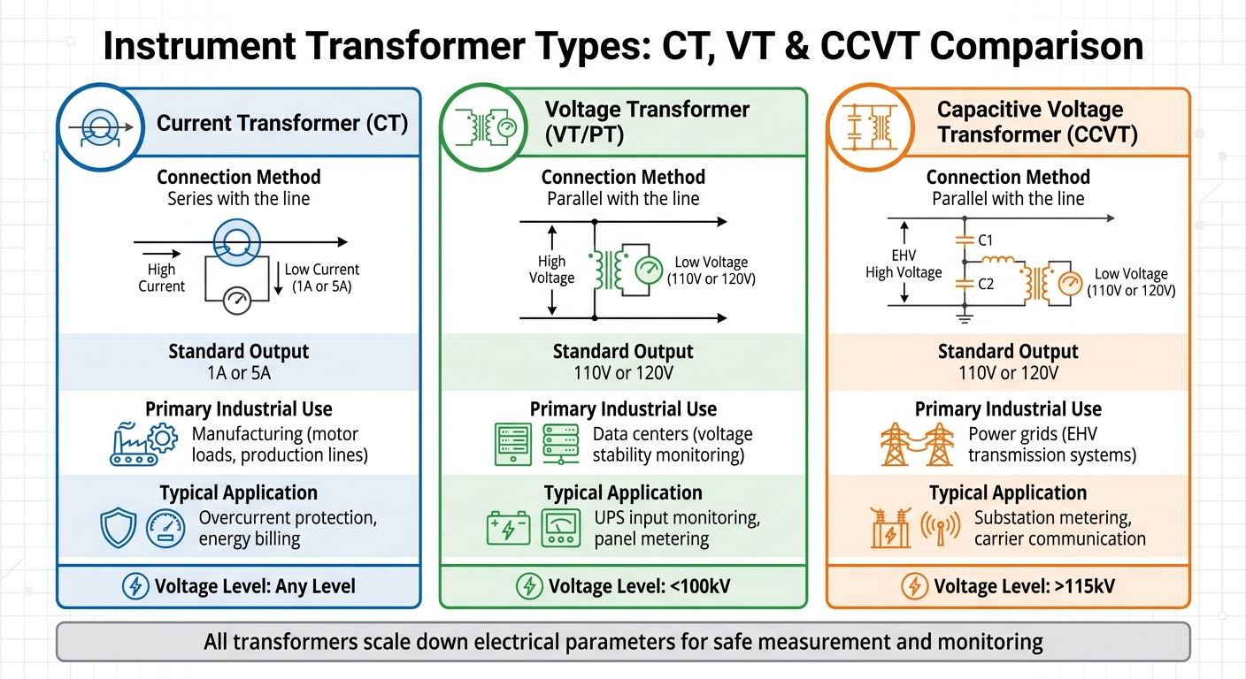
Instrument transformers play a vital role across various industries, each type tailored to specific needs. Here's a quick comparison of how Current Transformers (CT), Voltage Transformers (VT), and Capacitive Voltage Transformers (CCVT) are utilized:
| Transformer Type | Connection Method | Standard Output | Primary Industrial Use | Typical Application |
|---|---|---|---|---|
| Current Transformer (CT) | Series with the line | 1A or 5A | Manufacturing (motor loads, production lines) | Overcurrent protection, energy billing |
| Voltage Transformer (VT/PT) | Parallel with the line | 110V or 120V | Data centers (voltage stability monitoring) | UPS input monitoring, panel metering |
| Capacitive Voltage Transformer (CCVT) | Parallel with the line | 110V or 120V | Power grids (EHV transmission systems) | Substation metering, carrier communication |
This breakdown highlights how these transformers meet the demands of different industries, ensuring safety, efficiency, and reliability.
Industrial Use Cases
Accurate current and voltage measurements are essential for maintaining safety and optimizing performance in industrial environments. Let’s look at a few practical examples:
- Circuit Breakers: CTs designed for protection are integral to detecting overcurrent or short-circuit scenarios. For instance, during a motor stall or equipment fault, the CT sends a scaled signal to a protection relay. This relay then triggers the circuit breaker to isolate the issue, preventing further damage.
- UPS Systems in Data Centers: Indoor VTs are widely used here to monitor the quality of input voltage. These transformers, typically dry-type to avoid oil insulation, reduce fire risks in enclosed spaces. By providing a stable 120V signal, the VT allows the UPS control system to detect voltage irregularities - like sags, swells, or harmonics - that could disrupt server operations.
- Protection Relays: Modern digital relays paired with CTs and VTs ensure precise differential protection. Unlike older electromechanical models that consumed 5–10 VA per phase, newer digital relays require less than 0.5 VA per phase. This improvement not only enhances measurement accuracy but also simplifies transformer sizing.
When sourcing instrument transformers, platforms like Electrical Trader can help you find options tailored to your needs. For metering, look for precision classes such as 0.2 or 0.5. Protection circuits, on the other hand, often require ratings like 5P10 to maintain accuracy even during high-current fault conditions .
Advanced Types and New Technologies
Digital and Optical Instrument Transformers
Digital and optical instrument transformers are becoming the go-to choice for their precision, compact design, and improved safety features. These advanced devices, often referred to as Non-Conventional Instrument Transformers (NCITs), replace traditional iron cores with electronic or optical sensors, delivering digital outputs instead of analog signals.
Optical current transformers work using the Faraday effect, while voltage measurements rely on the Pockels effect. These sensors can measure electrical parameters up to 15,000 times per second and manage a dynamic range that stretches from near-DC levels to over 20 kA - performance levels that conventional transformers simply can't match.
Safety is another major benefit. By using fiber optic cables for data transmission, these transformers eliminate electrical hazards. They are also resistant to magnetic saturation and ferroresonance, issues that often plague traditional designs during fault conditions. For instance, in May 2026, Statnett in Norway implemented a Process Bus solution with digital instrument transformer technology compliant with IEC 61850-9-2 standards. This upgrade modernized substation communication and protection systems.
Similarly, Alabama Power's "Green Circuits" project highlights the practical advantages of these technologies. By deploying optical sensors on distribution feeders, the company achieved a 1% average voltage reduction, improving power delivery efficiency by as much as 2.14%.
"Having real-time voltage, current and power factor data allows utilities like Alabama Power to effectively manage the efficiency, reliability and demand response of their distribution systems",
said Trey Beasley, P.E., Vice President of Business Development at OptiSense Network.
These advancements build on the legacy of earlier instrument transformer technologies, offering greater precision and safety for modern electrical systems.
Specialized Instrument Transformers
Some instrument transformers are designed for highly specific applications. For example, pulse transformers play a key role in electronics and telecommunications. Unlike current transformers (CTs) and voltage transformers (VTs), which measure continuous AC signals, pulse transformers handle short bursts of electrical energy - essential for digital signal processing.
Optical sensors are also being used in extreme industrial settings, such as smelting operations. These environments demand transformers capable of managing high currents and varying voltage levels without the insulation challenges that traditional designs face.
These specialized devices demonstrate the adaptability of instrument transformer technology, catering to both niche and high-demand industrial applications.
Conclusion
Choosing the right instrument transformer is essential for maintaining safety, accuracy, and reliability in your electrical system. Whether you're selecting a current transformer (CT) for overcurrent protection, a voltage transformer (VT) for precise metering, or a capacitive voltage transformer (CVT) for handling extra-high-voltage scenarios, each decision plays a critical role in your system's overall performance and protection.
Pay close attention to precision and fault-handling ratings when making your selection. For example, leaving a CT secondary open-circuited can result in dangerously high voltages, while errors in burden calculations may lead to inaccurate measurements or transformer saturation.
Modern power networks often benefit from digital and optical instrument transformers. These advanced options provide enhanced measurement capabilities, wider dynamic ranges, and compatibility with smart grid technologies - features that are increasingly important in today's infrastructure.
When sourcing transformers, platforms like Electrical Trader offer a variety of options, from wound-type CTs and bar-primary designs to combined CTVT units. Their inventory includes components that meet international standards like IEC 61869 and IEEE C57.13, ensuring both quality and compliance. Whether you need standard secondary outputs of 5 A or 1 A, or specialized high-voltage equipment, a reliable marketplace simplifies the process of matching technical specifications to your unique requirements.
Always verify the specifications and installation details to ensure the safe and efficient operation of your system. Using dependable components from trusted sources like Electrical Trader helps maintain the integrity and performance of your electrical network.
FAQs
How do I choose the right CT or VT accuracy class for my application?
Choosing the right accuracy class for your Current Transformer (CT) or Voltage Transformer (VT) is all about understanding your specific application needs.
For metering purposes, you'll want a higher accuracy class, such as 0.2 or 0.5. These classes are designed to deliver precise energy measurements, which is critical for billing and monitoring.
On the other hand, protection applications require transformers that maintain linearity across a wide range of voltages and currents. This ensures they can detect faults quickly and effectively, safeguarding your system.
To achieve reliable performance and meet industry standards, always align the accuracy class with your system's voltage, current levels, and overall importance.
What happens if a CT secondary is left open, and how can I prevent it?
Leaving the secondary side of a current transformer (CT) open can lead to dangerously high voltage levels. This not only risks damaging the transformer but also creates potential safety hazards. To avoid such issues, always ensure the secondary is either connected to a load or short-circuited when not in use. This practice helps maintain safe operation and safeguards the equipment.
When should I use a CCVT instead of a standard VT/PT?
A CCVT (Capacitor Coupled Voltage Transformer) is perfect for high-voltage systems requiring steady voltage measurement during sudden changes, like faults or overvoltages. It merges a voltage transformer with a capacitor divider to ensure precise phase and amplitude readings. On the other hand, standard VTs/PTs work better for general metering in consistent, stable conditions. Opt for a CCVT when handling high voltages where transient stability and accuracy are essential.