




IEEE 1375-1998: Design Standards Explained
If I had to boil IEEE 1375-1998 down to one line, it would be this: it helps me decide how to protect a stationary battery system from the battery terminals to the first fuse or breaker.
That means I’m not using it to size the battery, lay out the full installation, or write the maintenance plan. I’m using it to answer a more direct design question: Do I want the system to trip fast to limit damage, or do I want it to stay online longer and isolate only the faulted part?
Here’s the short version:
- Scope: battery terminals through the first downstream protective device
- Main design choice: equipment protection vs. service continuity
- Device rules: use DC-rated fuses, breakers, and disconnects
- Current sizing point: set continuous current at 125% of max steady-state charge or discharge current
- Fault duty check: device AIC must be above battery short-circuit current plus charger contribution
- Example figure: an 800 Ah battery may deliver about 9,000 A into a short circuit
- Room safety: hydrogen must stay below 1% of room volume under fire code limits, with 0.4% as a tighter pre-entry OSHA threshold
- Ventilation rule of thumb: about 1 cfm per sq. ft.
- Related standards: IEEE 485, 1115, 484, 1187, 946, 1635, 450, and 1188 each cover a different part of the job
What matters most is this: IEEE 1375 is a protection guide, not a one-book battery design manual. I use it with other IEEE and UL standards to check grounding approach, interruption rating, fault current, disconnect method, and battery room safety.
Quick comparison
| Topic | What IEEE 1375 Helps Me Decide | What It Does Not Cover by Itself |
|---|---|---|
| Protection approach | Fast trip or coordinated fault isolation | Full selective coordination study details |
| Device selection | DC-rated fuse, breaker, disconnect choice | Full product compliance review alone |
| Fault protection | Ratings from battery to first device | Full downstream distribution design |
| Battery room concerns | Physical protection and gas safety points | Full ventilation design math alone |
| Battery project workflow | Where protection fits in the process | Battery sizing, installation, and testing standards |
If I’m designing a UPS, utility, telecom, or industrial DC battery system, this guide gives me the protection starting point. The rest of the article makes that line easier to follow in practice.
sbb-itb-501186b
Protection Goals: Equipment Damage vs. Service Continuity
IEEE 1375-1998 does not force a single protection approach. It leaves that call to the designer: isolate faults fast, or keep the system running with coordinated protection. That one decision shapes grounding, voltage choice, and how protective devices are set up.
How Protection Philosophy Shapes Design Choices
This protection philosophy shows up in three places: grounding, voltage class, and coordination method.
One of the biggest factors is whether the DC system is grounded or ungrounded. Grounded systems usually lean toward fast fault isolation. Ungrounded systems work differently. In many cases, a single ground fault will not trip the DC bus, which lets operators find the fault while the system stays online. That's a big reason ungrounded designs show up in high-reliability industrial settings.
Voltage matters too. As system voltage goes up, fault energy goes up with it. That means protective devices must be rated correctly for the job.
If service continuity is the main goal, selective coordination becomes a big part of the design. The idea is simple: only the device closest to the fault should trip, while the rest of the system keeps running. IEEE 1375 points to IEEE Std 242-1986 for that subject.
Equipment Protection vs. Service Continuity: A Side-by-Side Comparison
| Feature | Equipment-Protection-First | Continuity-of-Service-First |
|---|---|---|
| Primary Goal | Prevent physical damage to batteries, cables, and components | Maintain power to critical loads such as UPS systems and substations |
| Trip Sensitivity | High - trips at lower fault current | Lower - avoids nuisance trips |
| Device Coordination | Simple - rapid isolation | Complex - selective tripping |
| Redundancy | Minimal - often a single string or charger | High - often N+1 or independent parallel DC paths |
| Operational Impact | Higher shutdown risk | Local fault isolation; load stays energized |
In plain terms, this choice drives how fuses, breakers, and disconnects are picked. A design aimed at equipment protection will usually trip sooner and isolate faults fast. A design aimed at continuity will accept more coordination work so a single local fault doesn't take down the full DC system.
Protective Devices: Fuses, Breakers, and Disconnects
That choice shapes the whole protection plan. In plain English, it tells you whether the first device should trip as fast as possible or whether it should be set up to keep more of the system online through coordination. Once that approach is clear, pick devices that can clear fault current right at the battery-to-first-device boundary. After that, the main design call is simple: does the device need to interrupt a fault, isolate a string, or do both?
What to Check When Selecting DC Protection
Use only DC-rated devices. DC arcs don't go out on their own at current zero, so an AC-rated device isn't enough here.
For sizing, set continuous current at 125% of the maximum steady-state current, whether the battery is charging or discharging. Also set AIC above the battery manufacturer's published short-circuit current, plus any charger contribution. As a reference point, a standard 800 Ah battery can deliver about 9,000A into a short circuit. And that fault current doesn't come from just one place. It comes from both the battery and the charger, so both have to be included in the calculation. If maintenance isolation is needed, use a dedicated disconnect breaker for each battery string.
Fuses vs. Circuit Breakers vs. Disconnect Switches
Each device has its own job. Mixing them up can cause trouble fast.
| Feature | Fuses | Circuit Breakers | Disconnect Switches |
|---|---|---|---|
| Interrupting Capacity | Very high (up to 200kA) | Moderate to high (5kA–200kA) | Maintenance isolation only |
| Adjustability | None (fixed rating) | Often adjustable trip settings | None |
| Maintenance | Must be replaced after a trip | Resettable; can be tested periodically | Manual operation; provides visible air gap |
| Primary Use | Protecting against massive short circuits | String isolation and frequent switching | Physical safety isolation only |
If you need very high AIC, a fuse in series with a breaker can be a smart setup. You get high interruption capacity from the fuse and resettable operation from the breaker, often at a lower cost.
Sourcing Rated Components for Real Projects
Once the duty is defined, source only parts that match the system's DC fault duty. Electrical Trader lists DC-rated breakers, fuses, switchgear, and related power-distribution equipment for stationary battery projects. Before anything goes into the field, verify the DC rating, AIC, voltage, and battery-chemistry compatibility.
Physical Protection, Ventilation, and Battery Room Safety
Once the DC path is protected, the room becomes the next line of defense. IEEE 1375 also covers room layout, enclosure protection, gas hazards, and maintenance access.
Ventilation and Hydrogen Control
Lead-acid batteries can produce hydrogen while charging. That means the room needs enough ventilation to keep gas levels under code limits. Under IFC and NFPA 1, hydrogen must stay below 1% of room volume. Before confined-space entry, OSHA sets a tighter limit of 0.4%.
A common continuous ventilation rate is 1 cfm per square foot. In plain terms, air should come in low and leave high, since hydrogen rises. Hydrogen detectors should also sit at the highest point in the room.
Ventilation should not rely on someone noticing a problem and flipping a switch. The system should be tied to the gas sensors so fans start on their own when hydrogen hits a preset level, usually 1% LEL.
IEEE/ASHRAE 1635 lays out the ventilation calculations.
Taken together, the room controls cover ventilation, detection, access control, and enclosure protection.
Hazard Controls in Battery Installations
| Hazard Control | Hazard Addressed | Design Purpose |
|---|---|---|
| Ventilation Provisions | Hydrogen gas accumulation | Dilutes hydrogen below safe limits |
| Hydrogen Detection | Ventilation failure or excessive gassing | Triggers alarms or emergency ventilation |
| Flame Arrestors | External ignition sources | Blocks ignition sources |
| Enclosure Construction | Mechanical damage and environmental exposure | Protects from impact and exposure |
| Access Control & Signage | Unauthorized entry and accidental contact | Restricts access |
| Mechanical Protection | Physical impact or seismic activity | Prevents physical damage and seismic impact |
Applying IEEE 1375-1998 in U.S. Facility and UPS Projects
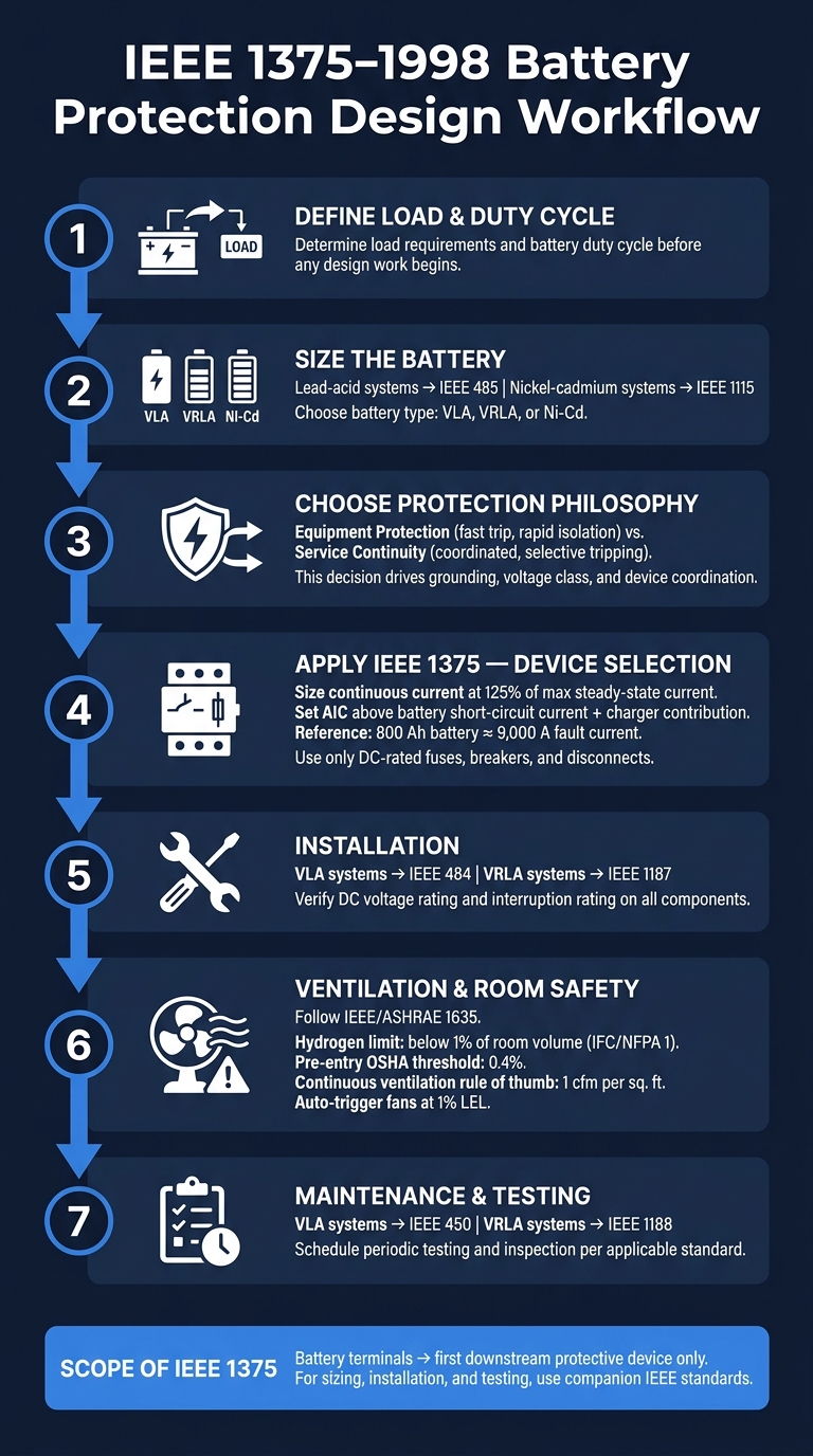
IEEE 1375-1998 Battery Protection Design Workflow
Once you've settled on the protection approach, the next move is putting it to work in a U.S. facility or UPS project.
A Step-by-Step Design and Review Process
Begin with the basics: load, battery sizing, and duty cycle. For lead-acid systems, use IEEE 485. For nickel-cadmium systems, use IEEE 1115. After that, choose the battery type that fits the job: VLA, VRLA, or Ni-Cd.
With the battery choice in place, IEEE 1375 becomes the main guide for protection design. Use it to apply your protection philosophy during grounding and device-selection work. Size DC protection using the fault-current data in the standard. For installation, turn to IEEE 484 or IEEE 1187, and use IEEE 1635 for ventilation. Then set maintenance and testing schedules under IEEE 450 or IEEE 1188.
Which Standard Guides Which Decision
Each project decision should tie back to the standard that covers that part of the work.
| Design Task | Primary Standard |
|---|---|
| Protection Philosophy & Device Selection | IEEE 1375 |
| Battery Sizing (Lead-Acid) | IEEE 485 |
| Battery Sizing (Nickel-Cadmium) | IEEE 1115 |
| Installation (VLA) | IEEE 484 |
| Installation (VRLA) | IEEE 1187 |
| Ventilation & Thermal Management | IEEE 1635 |
| Maintenance & Testing (VLA) | IEEE 450 |
| Maintenance & Testing (VRLA) | IEEE 1188 |
| UPS Battery Selection | IEEE 1184 |
| DC Auxiliary Power System Design | IEEE 946 |
That division keeps design, installation, and maintenance work in the right lane. It also helps you avoid using IEEE 1375 for sizing, installation, or testing calls that fall outside its scope.
Key Design Points to Remember
IEEE 1375-1998 deals directly with protection philosophy and DC interruption ratings for stationary battery systems. Its scope covers the battery and DC components up to and including the first protective device downstream of the battery terminals. You still need to match component ratings to the actual installation and check UL 489, UL 198L, and UL 98 for component-level safety compliance. Before purchase, verify both DC voltage and interruption ratings.
FAQs
When should I choose fast tripping over selective coordination?
Choose selective coordination when a fault needs to stay contained to the affected circuit so the rest of the system keeps running. That matters in places like healthcare facilities, elevator systems, and emergency power setups, where a broader outage can cause much bigger problems.
Choose fast tripping when your main goal is to cut arc flash energy and limit physical damage during a fault. In some mission-critical setups, teams will accept less coordination in the instantaneous region if it means lowering total fault energy.
How do I calculate the correct DC fault duty?
IEEE 1375-1998 does not specifically cover how to calculate DC fault duty. Its focus is guidance for protecting stationary battery systems, not design rules or fault-current calculation methods.
For load requirements and battery sizing in stationary applications, engineers usually turn to IEEE 485. Battery sizing should be based on the worst-case load profile, with room for factors like temperature, battery aging, and design margins.
What standards do I use with IEEE 1375?
IEEE 1375-1998 is an inactive-reserved guide for protecting stationary battery systems. It is not a standard with strict requirements.
That matters because the document gives design options instead of telling you that you must follow specific accompanying standards. In plain English: it points you in a direction, but it doesn't act like a rulebook.
If you're sourcing protective devices or related parts, Electrical Trader offers breakers, fuses, and other power distribution equipment that can support those design options.





