
Common IEEE 1100-2005 Compliance Issues
If your facility passes NEC checks but still has resets, bad data, or early equipment failure, the problem is often IEEE 1100-2005 gaps.
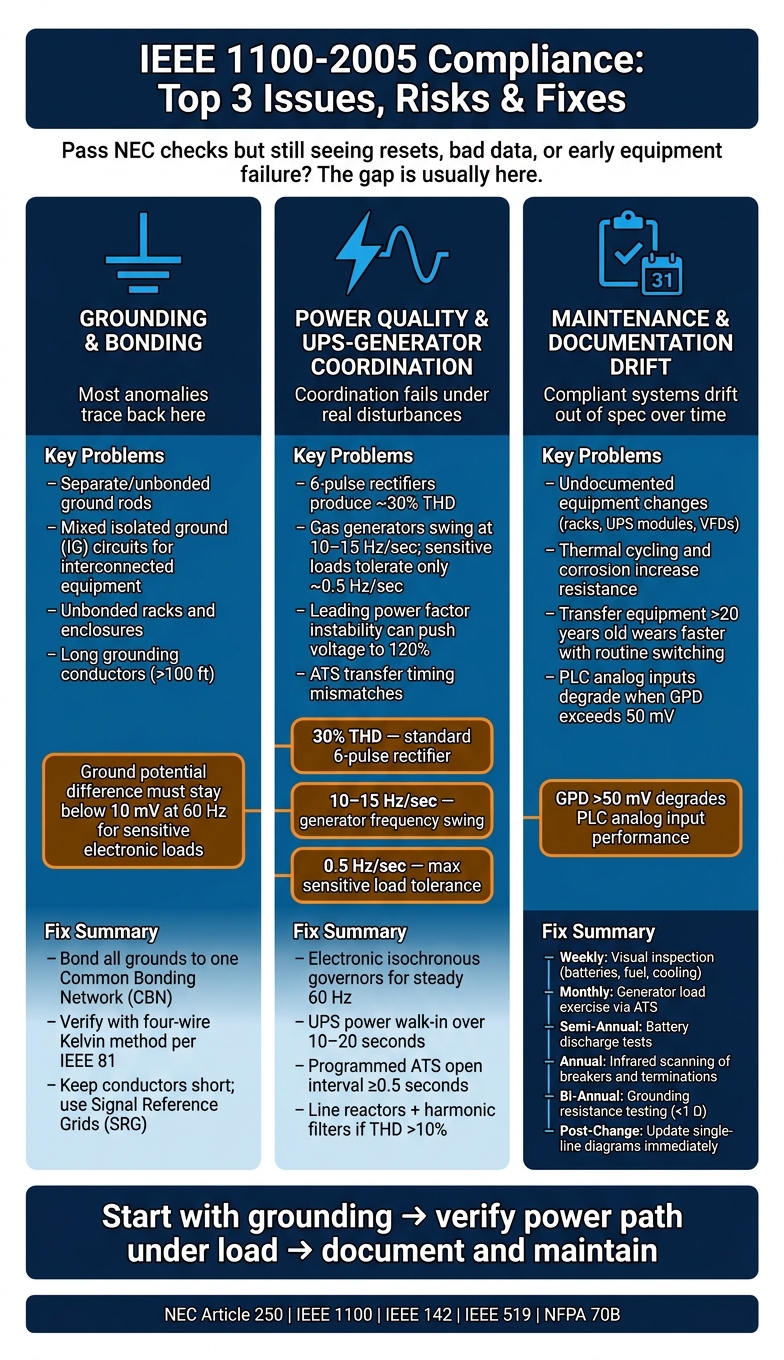
I’d boil this article down to 3 trouble spots:
- Grounding and bonding mistakes that create ground loops, noise, and voltage differences
- Power quality and UPS-generator mismatch during sags, harmonics, and transfer events
- Maintenance drift from loose connections, old gear, and outdated records
A few numbers make the risk clear. A standard 6-pulse rectifier can produce about 30% THD. Gas generators can swing at 10 to 15 Hz/second, while some sensitive loads may tolerate only about 0.5 Hz/second. And for sensitive electronic loads, ground potential difference should stay below 10 mV at 60 Hz.
Here’s the short answer: I’d start by making sure all grounds are bonded into one common system, then verify UPS, ATS, and generator coordination with actual testing, and finally put recurring checks in place for grounding, torque, IR scans, and drawings.
Quick overview:
| Issue | What goes wrong | What to do |
|---|---|---|
| Grounding and bonding | Separate rods, mixed IG circuits, unbonded racks | Use one bonded grounding system and verify it with testing |
| Power quality | Harmonics, transfer failures, generator instability | Measure events, size and coordinate UPS/ATS/generator correctly |
| Maintenance | System changes and wear push performance out of spec | Use scheduled testing, inspections, and record updates |
If I were reading this for a fast answer, that’s it: bond everything correctly, test the power path under load, and keep the system documented and checked over time.
IEEE 1100-2005 Compliance: Top 3 Issues, Risks & Fixes
Chemical Grounds and Sensitive Equipment Grounding Considerations
sbb-itb-501186b
Grounding and Bonding Problems That Cause Noise and Equipment Failures
Grounding and bonding failures sit behind a lot of power-system trouble. That’s why IEEE 1100-2005 work usually needs to start here.
Problem: Isolated Grounds, Separate Ground Rods, and Unbonded Equipment
A common mistake is treating an isolated ground (IG) system like a fully separate path for “clean” power. On paper, that can sound fine. In practice, it falls apart fast.
Once connected devices share USB or data cables, those two grounding systems are tied together. That creates a ground loop and circulating current, which can corrupt data or trigger intermittent lockups. Separate ground rods installed just for IT gear make the situation worse. If those rods aren’t bonded back to the building’s main grounding electrode system, voltage differences can build up between the IT equipment and the rest of the facility. During lightning or a fault, that voltage gap can do real damage. IEEE 1100-2005 requires all grounding systems to be bonded to the building’s main grounding electrode system.
Unbonded racks and enclosures create another problem. Paint and powder coating on rack rails and cabinet frames can block metal-to-metal contact, so equipment ends up sitting at different voltages. At first, the signs can seem minor: intermittent errors, flaky control signals, random instability. But those issues often point to an equipotential bonding failure, not a separate device problem.
Solution: Build a Common Bonded Grounding System
The fix is straightforward in concept: get rid of separate grounding paths. Bond all metallic parts to one common grounding system.
IEEE 1100-2005 recommends a Common Bonding Network (CBN) or, in larger facilities, a Mesh Common Bonding Network (MCBN), where metallic parts like UPSs, generators, IT equipment, rack enclosures, PDUs, and panelboards are intentionally interconnected. When everything is bonded together, you reduce the voltage differences that cause loops, noise, and resets.
For sensitive analog signals like 4–20 mA loops, ground cable shields at one end only, usually at the PLC or DCS end. That helps stop the shield from acting like a loop antenna. Grounding conductors should also stay short, because long grounding conductors lose effect during fast transients. Verify grounding with the four-wire Kelvin method per IEEE 81. Keep measurements within the applicable resistance limits.
The table below sums up common noncompliant practices and the right fix:
| Noncompliant Practice | Risk | Typical Symptom | Corrective Action |
|---|---|---|---|
| Separate, unbonded ground rods | High voltage potential during faults or lightning | Equipment damage; unstable signals | Bond all rods to the building grounding electrode system |
| Mixed IG and standard circuits for interconnected equipment | Circulating currents through data cables | Intermittent lockups; unexplained resets | Power all interconnected equipment from the same grounding topology |
| Unbonded racks and enclosures | EMI/RFI noise; shock hazard | Intermittent errors; touch potential issues | Remove paint at contact points; use bonding jumpers to the ground bus |
| Long grounding conductors (>100 ft) | High inductive impedance at high frequencies | Unexplained resets during transients | Keep conductors short; use Signal Reference Grids (SRG) where needed |
Once grounding is stable, the next place to look is power quality during sags, harmonics, and transfer events.
Power Quality Gaps and UPS-Generator Integration Failures
Problem: Sag Ride-Through, Harmonics, and Transfer Events Are Underestimated
Once grounding is stable, the next set of failures usually shows up when nonlinear loads and transfer events push the UPS and generator at the same time. A lot of facilities assume the equipment nameplate tells the whole story. It doesn’t. UPS, ATS, and generator coordination often falls apart when actual power disturbances hit the system.
UPS rectifiers and VFDs draw current in pulses. That creates about 30% THD on a standard 6-pulse rectifier, which is enough to overheat generator windings and disrupt control logic. During a utility outage, gas-fueled generators can swing at 10 to 15 Hz/sec. Many UPS-connected sensitive loads, by contrast, can handle only about 0.5 Hz/sec. That gap matters. It can stop synchronization and block maintenance bypass when it’s needed most.
Another risk is easier to miss: leading power factor instability. At partial load, UPS input filters can look too capacitive to the upstream source. As Paul Schlattman and Robert W. Weber noted:
"The generator voltage regulator can lose control of system voltage when presented with a leading power factor, preventing the generator from picking up the UPS load."
If the UPS input filter is the only load on the generator, system voltage can climb to 120% if the exciter can’t absorb the excess energy.
Solution: Measure Power Quality and Coordinate UPS, ATS, and Generator Design
The fix starts with measurement, not guesswork. Use power-quality monitoring at critical panels, and run on-site load-bank testing to record voltage dip and recovery times. That gives you a clear picture of what the system is doing during transfer and restart events.
Generator and UPS coordination needs to be spelled out in the design. For the generator, specify:
- Electronic isochronous governors to hold a steady 60 Hz output across load levels
- An AVR with three-phase sensing and a separately excited alternator to avoid instability from UPS rectifier notching
- A generator alternator with subtransient reactance of 15% or less to limit voltage distortion under nonlinear loads
On the UPS and transfer side, check a few items closely. Confirm the UPS has a power walk-in feature so it adds load to the generator over 10 to 20 seconds instead of all at once. For ATS timing, use a programmed ATS transition with an open interval of at least 0.5 seconds to avoid nuisance breaker trips from inductive UPS loads. A four-pole ATS with switched neutral can stop ground-loop currents and nuisance tripping of ground-fault protection during transfer, though the grounding plan has to be done with care. If the design uses a 3-pole ATS with nonlinear loads, make sure neutral capacity is at least equal to phase-conductor capacity.
For harmonics, start with line reactors at VFD or UPS inputs. If THD still stays above 10%, add passive or active harmonic filters to cut distortion and reduce generator derating.
The core fixes are pretty clear: double-conversion UPSs, harmonic filters, line reactors, and proper ATS and generator coordination.
Even when a system is well coordinated, it can drift out of spec over time if testing and records aren’t kept up to date.
Maintenance, Documentation, and Standards Alignment Issues
Problem: Equipment Changes Outpace Inspections and Records
A system can meet code one year and drift out of line a few years later. That usually happens through small, routine changes: a new rack, an added UPS module, or a VFD swap. On paper, none of that looks dramatic. In practice, each change can affect grounding and power quality if the records don’t keep up.
Then time starts doing its own damage. Thermal cycling, vibration, and corrosion can increase resistance and add electrical noise on sensitive circuits. That’s bad news for controls and electronics. For sensitive electronic loads, ground potential difference should stay below 10 mV at 60 Hz, and many PLC analog inputs start to lose performance when GPD goes above 50 mV.
Older transfer equipment can also turn into a weak link. If a unit is more than 20 years old, routine switching can wear it down faster.
"Routine switching can greatly reduce life expectancy of equipment that is greater than 20 yr old."
Solution: Set Up a Repeatable Compliance Review and Maintenance Program
The fix is pretty simple in concept: don’t treat compliance as a one-time project. Use a maintenance program that checks system performance, not just NEC minimums. Once grounding and power quality issues are corrected, the next job is keeping the system in that same condition.
NEC Article 250 sets the minimum safety bar, while IEEE 1100 focuses on performance for sensitive loads. Grounding should be verified with the four-wire Kelvin or fall-of-potential method. IEEE 142 helps guide grounding-system design decisions, and IEEE 519 addresses harmonic control for nonlinear loads.
In day-to-day maintenance, a few checks do a lot of work:
- Add torque checks, infrared scanning, and grounding tests to a recurring schedule.
- Use infrared scanning to spot overheating breakers and loose terminations before they fail.
- Perform torque checks after maintenance or any equipment change.
- Update as-built drawings right away whenever equipment, conductors, or terminations change.
- Replace worn parts without delay to bring reliability back.
The table below shows a practical maintenance lifecycle for IEEE 1100 compliance:
| Interval | Key IEEE 1100 / NFPA Concern | Primary Verification Activity |
|---|---|---|
| Weekly | EPSS Readiness (NFPA 110) | Visual inspection of batteries, fuel, and cooling systems |
| Monthly | Transfer Reliability | Exercise generator under load via ATS switching; monitor for ride-through failures |
| Semi-Annual | Battery Health | Discharge tests and corrosion checks on UPS and BAS backup batteries |
| Annual | Thermal Integrity | Infrared scanning of breakers, terminations, and transformers |
| Bi-Annual | Grounding System Integrity | Grounding resistance testing using the four-wire Kelvin method (<1 Ω for instrument grounds) |
| Post-Change | Documentation Accuracy | Update single-line diagrams and label new conductors and termination points |
These checks should line up with the standards that apply to each part of the system:
| Standard | Primary Focus | Role in Facility Maintenance |
|---|---|---|
| NFPA 70 (NEC), Article 250 | Safety baseline | Mandatory grounding and bonding minimums |
| IEEE 1100 | Equipment performance | Quiet grounds and power quality for sensitive electronic loads |
| IEEE 142 | Industrial grounding | Grounding-system review |
| IEEE 519 | Harmonic control | Harmonic checks for nonlinear loads |
| NFPA 70B | Equipment maintenance | Framework for a formal electrical maintenance program |
At this stage, the biggest compliance risks usually aren’t dramatic failures. They come from the slow stuff: undocumented changes, loose connections, and weak upkeep of grounding and transfer equipment.
Conclusion: The Most Common IEEE 1100-2005 Issues and How to Fix Them
Across the three problem areas above, the pattern is pretty clear: most IEEE 1100-2005 failures come back to three things - grounding and bonding, power quality, and maintenance drift.
Grounding is usually the first place to start. Most anomalies trace back, either directly or indirectly, to bonding and grounding issues. That makes it the base layer for everything else.
Once grounding is in good shape, power quality tends to become the next bottleneck. Internal surges and switching disturbances cause many electronic failures, so outside protection by itself won’t cover the whole problem.
The last piece is making sure those fixes stay in place. Field changes and poor records are often what push compliant systems out of spec over time. IEEE 1100-2005 is about performance as much as safety, so compliance needs to be maintained with testing, updated records, and preventive maintenance.
When facilities handle all three at the same time, they can cut nuisance trips, help equipment last longer, and improve uptime.
FAQs
How do I know if ground loops are causing our resets?
Ground loops show up when two grounding points sit at different voltages. That voltage gap lets current flow through data cables or cable shields when it shouldn't. The result can be messy: equipment resets, network errors, and downtime.
A good first check is to look for steady-state ground current in data cables with an inductive meter probe. If you need to catch transient voltages, use an oscilloscope between the bonded ground bus and the isolated ground bus. It also helps to inspect the setup for improper bonding or shields grounded at more than one point.
What tests should we run on our UPS, ATS, and generator?
Follow NFPA 110 testing protocols to keep backup power gear ready when it counts.
- Generator: Run a monthly exercise test. If the monthly load stays under 30%, do an annual load bank test. Then complete a full exercise every 36 months at 75% to 100% load for at least 1 hour.
- ATS: Perform monthly automatic transfer tests. Also do an annual full transfer test and inspect the contacts.
- UPS batteries: Do weekly visual checks, monthly voltage or conductance testing, and annual load tests.
These checks help confirm each part of the backup power setup can do its job under working conditions, not just on paper.
How often should IEEE 1100-related checks be performed?
IEEE 1100-2005 does not set a fixed schedule for inspections or testing.
Instead, it focuses on using measurement and diagnostic tools to find and fix power quality problems when they show up.
For day-to-day system health, the standard recommends proactive baseline surveys before a project starts or before major system changes take place. After that, follow-up measurements help confirm that any mitigation equipment is working as intended.


