
Why Poor Grounding Causes Power Quality Issues
Poor grounding is a major cause of electrical problems in facilities. It leads to voltage instability, equipment failures, and increased electrical noise. Without a proper grounding system, sensitive electronics can malfunction, circuit breakers may trip unnecessarily, and safety risks like fires become more likely.
Here’s what you need to know:
- Grounding provides a stable voltage reference and a safe path for fault currents.
- Standards recommend a ground resistance of 5 ohms or less, with critical sites requiring below 1 ohm.
- Common issues include ground loops, improper neutral-to-ground connections, and aging components.
- Poor grounding increases harmonic distortions, overheats conductors, and disrupts communication systems.
Prevention tips:
- Perform regular grounding tests (e.g., Fall of Potential, clamp-on testing).
- Inspect and maintain connections to avoid loose or faulty components.
- Use high-quality materials like copper conductors and reliable clamps.
Proper grounding isn’t just about safety - it ensures stable, efficient power delivery and extends the life of your equipment.
Grounding and bonding: Power quality
Grounding Fundamentals and Power Quality
Grounding System Standards and Resistance Requirements by Facility Type
What Is Grounding?
Grounding creates a low-resistance link between electrical circuits, equipment, and the earth. This connection provides a stable voltage reference and a safe pathway for fault currents, which helps protect both people and equipment while minimizing electrical noise. Although the goal is zero ohms of resistance, practical limitations mean standards define acceptable resistance levels.
When done correctly, grounding ensures all equipment shares the same voltage level (equipotential), eliminating dangerous voltage differences and stray currents. Established standards ensure grounding systems maintain safety and consistent power quality.
Grounding System Standards
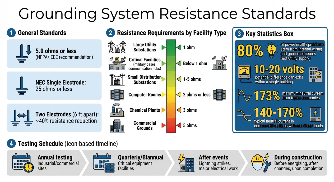
Organizations like the National Fire Protection Association (NFPA) and the Institute of Electrical and Electronics Engineers (IEEE) recommend that grounding systems achieve a resistance of 5.0 ohms or less for proper operation. However, critical facilities - such as military bases or communication hubs - often require grounding resistance below 1 ohm to maintain reliability and safety during fault conditions. For small distribution substations, resistance typically falls between 1 and 5 ohms, influenced by local soil characteristics.
Testing protocols are essential to verify grounding performance. Key tests include selective earth and stakeless ground resistance evaluations, which should occur at several stages: before energizing equipment, after construction changes, upon building completion, and during annual maintenance. Soil resistivity tests also play a crucial role in determining the best electrode placement to ensure the system can handle faults over time. Furthermore, the National Electrical Code (NEC) strictly prohibits neutral-to-ground connections downstream from the service entrance - except in separately derived systems - to prevent ground loops that can cause electrical shocks and diminish power quality.
Industrial surveys in sectors like metalworking, chemical production, textiles, and food processing consistently highlight poor grounding and faulty wiring as leading causes of internal power quality problems. These findings emphasize the critical role of proper grounding in maintaining reliable and safe electrical systems.
How Poor Grounding Affects Power Quality
Voltage Instability and Equipment Failures
When grounding lacks a stable reference point, voltage levels can fluctuate unpredictably, leading to instability across the system. This instability often results in severe voltage fluctuations and persistent flickering, which can disrupt operations and damage sensitive electronics. High impedance in neutral circuits or neutral-to-ground connections is a common culprit behind these issues.
Circuit breakers and fuses rely on low-impedance pathways to function properly. If grounding resistance is too high, fault current detection is delayed, increasing the risk of equipment damage. According to electric utility engineers, 80% of power quality problems reported by customers stem from internal wiring and grounding issues, not from the utility's power supply.
Improperly installed extra ground rods can create secondary pathways for lightning transients. This leads to uneven ground potentials, which overload conductors and cause dangerous voltage spikes. Poor grounding can also result in the accumulation of triplen harmonics, which overheat neutral conductors and increase the risk of insulation failure and even fires. These voltage instabilities often snowball into further complications, such as heightened harmonic distortions and increased electrical noise.
Harmonics and Electrical Noise
Faulty grounding doesn't just destabilize voltage - it exacerbates harmonic distortions as well. Modern facilities, packed with computers, variable frequency drives, and LED lighting, face unique challenges from non-linear loads. These loads draw current in pulses rather than smooth sinewaves, intensifying harmonic distortions in systems with poor grounding. In some cases, non-linear loads in commercial settings can push neutral current to 140–170% of the phase current - and in extreme situations, up to 240%. Worst-case triplen harmonics generally cap these increases at 173%.
"The grounding system allows all equipment to have the same reference voltage. It stabilizes equipment operation and prevents objectionable currents on communication lines." - Marty Martin, P.E., Copper Development Association
When grounding fails to provide an equipotential reference, potential differences between ground points can create circulating ground currents. These ground loops disrupt sensitive equipment and communication lines. Acting like shorted coils, even minor magnetic field changes can induce large interfering currents due to the loop's near-zero impedance. Harmonic currents from non-linear loads interact with system impedance, distorting voltage waveforms. Without proper grounding as outlined in established standards, these distorted currents accelerate electronic device failures, while also overheating conductors and transformers throughout the facility.
Common Grounding Faults and Their Effects
Ground Loops and Circulating Currents
Ground loops occur when interconnected devices have multiple paths to ground. This usually happens when signal cables - like those for audio, video, or data - connect equipment that already has separate grounds through their power cords. The resulting loop acts like a single-turn transformer, picking up electromagnetic interference from nearby AC wiring.
Even weak magnetic fields can induce significant currents in these low-resistance loops. The effects? A 60 Hz hum in audio systems, rolling hum bars in video feeds, and interruptions in digital data networks.
Ground potential differences within a single building can vary by as much as 10 to 20 volts, often due to leakage-induced voltage drops. These differences create circulating currents through equipment chassis and cable shields, leading to disruptions in sensitive electronics and communication systems. This becomes especially troublesome in large data networks, where ground loops can corrupt signals or cause intermittent malfunctions.
In addition to ground loops, improper neutral-to-ground bonds can further destabilize systems.
Improper Neutral-to-Ground Bonds
According to the National Electrical Code, a system should have only one neutral-to-ground bond, typically located at the service entrance. Additional bonds elsewhere in the system can redirect load return currents onto grounding conductors, leading to interference and compromising fault detection.
"A well-designed G&B [Grounding and Bonding] network turns an electrical ground fault into a fast, controlled event. A compromised one turns it into a lingering hazard that energizes metal and waits for contact."
- Frank Baker, Technical Editor, Electricity Forum
When neutral currents flow on grounding conductors, they can interfere with equipment performance and even prevent circuit breakers from functioning properly. This creates both operational and safety concerns. Non-linear loads, such as computers and printers, introduce triplen harmonics into the neutral. Improper bonding can force these currents through undersized or shared conductors, potentially causing the neutral to overheat and fail, which poses a serious fire hazard.
| Condition | Possible Cause | System Impact |
|---|---|---|
| Ground currents on grounding system | Extra neutral-to-ground bond | Neutral current flows on ground/shields; safety risk |
| Extreme voltage fluctuations | High impedance in neutral circuit | Equipment malfunction; potential damage |
| High neutral-to-ground voltage | High impedance ground | Electronic equipment noise and data errors |
| Scorched insulation or warm panels | Overloaded wiring, faulted conductor, or bad connection | Fire hazard; conductor failure |
These bonding issues intensify power quality problems by further undermining the system's voltage stability.
sbb-itb-501186b
Prevention and Mitigation Strategies
Addressing power quality issues caused by poor grounding requires a combination of thorough testing, consistent maintenance, and the use of reliable components.
Testing and Monitoring Grounding Systems
Effective testing can catch grounding faults before they lead to failures. One widely recognized method is the Fall of Potential Method, described in IEEE Standard 81. This technique measures ground resistance by plotting resistance values across multiple points until a "plateau" indicates the effective resistance.
For systems that need to stay operational, clamp-on ground testing offers a non-intrusive way to measure resistance without disconnecting the grounding electrode. Another option, Four-terminal (Kelvin Bridge) testing, uses separate terminals for current and voltage, eliminating lead and contact resistance for precise readings.
According to the National Electrical Code, a single grounding electrode must test at 25 ohms or less. If resistance is higher, adding a second electrode at least 6 feet away can reduce resistance by about 40%. Stricter standards apply to sensitive environments: 5 ohms for commercial grounds, 3 ohms for chemical plants, 2 ohms or less for computer rooms, and 1 ohm for large utility substations.
"The Code is concerned with safety, not performance. The building may be protected from lightning and electrical faults, but still have 'noise' on datacom lines." - Jeffrey R. Jowett, Megger
Grounding tests should be scheduled annually for industrial and commercial sites. Facilities with critical equipment or high-power machinery may need testing quarterly or biannually. Additionally, re-testing is essential after events like lightning strikes or major electrical work.
Accurate testing lays the groundwork for reliable systems, which must be paired with diligent maintenance and timely upgrades.
Regular Maintenance and Upgrades
Routine inspections help catch issues like loose connections or faulty breakers, which can lead to electrical impulses. Thermal imaging can identify hot spots in panels or junction boxes, often signaling potential fire hazards caused by faulty breakers or connections.
Maintenance also ensures safety grounds haven’t been bypassed by unauthorized adapters, which increase the risk of shock and equipment damage during faults. High-impedance neutral-to-ground bonds, which cause voltage fluctuations harmful to sensitive electronics, must also be addressed.
For systems with heavy electronic loads, neutral conductors may need upgrades to handle triplen harmonics. In extreme cases, neutral current can reach up to 173% of phase current, making these upgrades crucial to avoid overheating and system failure. Upgrading to a single, bonded grounding electrode system can also eliminate ground loops and circulating currents, which often interfere with communication circuits.
While maintenance is essential, using high-quality components adds another layer of reliability.
Using Quality Electrical Components
A system’s reliability depends on both its design and the quality of its hardware. Components like specialized ground clamps help maintain electrical continuity over time and prevent high-impedance paths that can lead to voltage fluctuations.
"Connection integrity depends on hardware quality as much as system design, which is why the role of an electrical ground clamp is critical to maintaining long-term grounding continuity." - Pablo Diaz, P.Eng.
All grounding conductors should be rated for the system's amperage and length to prevent overheating during faults. For sensitive electronics, insulated ground receptacles - marked by an orange face or a "∆" symbol - help isolate the grounding circuit from electrical noise. Instead of using grounding plug adapters, install new three-prong outlets to ensure a permanent safety ground.
Platforms like Electrical Trader offer access to high-quality components, from specialized clamps to properly rated conductors and outlets. Subpar hardware or loose connections can lead to issues like arcing, scorched insulation, and burnt smells in panels or junction boxes - problems that can be avoided with quality materials.
Conclusion
Proper grounding plays a crucial role in ensuring stable and reliable power systems. As Pablo Diaz, P.Eng., explains:
"Grounding is a control system. It manages voltage behavior so faults remain survivable instead of destructive".
An effective grounding system does more than just stabilize voltage - it also clears faults, manages harmonics, and shields against transients. These functions help prevent equipment failures, reduce electrical noise, and address potential safety risks.
Many common issues can be avoided with good design, regular testing, and the use of high-quality components. Some essential best practices include: maintaining a single neutral-to-ground bond at the service entrance, bonding all grounding electrodes, opting for copper conductors, oversizing neutrals for non-linear loads, and conducting routine testing.
The quality of components is just as important as the system design. Poor connections, undersized conductors, or low-grade hardware can undermine the entire setup. Reliable sources like Electrical Trader provide access to the components necessary for dependable grounding systems.
While grounding often operates unnoticed, its effects on power quality, equipment durability, and safety are far-reaching. Prioritizing proper grounding now can save significant costs and prevent serious issues down the line.
FAQs
How can I tell if my facility’s grounding is causing power quality issues?
Inspecting the wiring and grounding systems is key to spotting whether grounding is impacting power quality. Pay attention to loose connections, extra ground paths that aren’t needed, or corroded conductors - these are frequent culprits behind power fluctuations. Routine inspections can go a long way in preventing problems and ensuring consistent power performance.
What’s the difference between grounding for safety and grounding for low noise?
Grounding plays a critical role in protecting both people and equipment. By creating a low-resistance path to the earth, it ensures that hazardous voltages are safely redirected during electrical faults. This significantly lowers the risk of electric shocks and prevents damage to connected equipment.
Grounding for Low Noise
In environments with sensitive electronics, grounding is essential for minimizing electromagnetic and radio-frequency interference (EMI/RFI). Such interference can disrupt devices and degrade signal quality. Using methods like isolated ground systems helps maintain clear signals and ensures reliable performance, even in areas with high levels of electrical noise.
When should I test grounding resistance, and which test should I use?
Grounding resistance needs to be checked when the system is initially installed and periodically afterward - typically every three years. However, if there are signs of wear or deterioration, testing should be done more frequently. To evaluate the system's resistance, use a ground resistance test. If you notice an increase in resistance by more than 20%, it's time to take corrective measures. This might involve adding new ground rods or replacing existing ones to ensure both safety and system performance are upheld.


