Hydrogen fuel cell maintenance checklist
If you maintain a hydrogen fuel cell, the job comes down to this: shut it down safely, confirm zero energy, check for leaks, inspect filters and coolant, verify sensors and wiring, then log every result.
I’d use this checklist to keep service work consistent across sites. It covers the steps that matter most for safety and uptime, including lockout/tagout, ventilation, hydrogen leak testing, coolant checks, sensor calibration status, electrical connection checks, and performance log review. That matters because the U.S. already has 500+ MW of stationary backup fuel cells installed, so routine service is not optional.
Here’s the full flow in plain terms:
- Start with shutdown and lockout/tagout
- Confirm zero voltage and safe pressure
- Check ventilation, ignition risks, and PPE
- Inspect the enclosure, hoses, piping, and alarms
- Review air filters, hydrogen filters, and coolant condition
- Test for hydrogen leaks and pressure loss
- Check sensor readings, alarms, and calibration dates
- Inspect cables, grounding, and torque points
- Review trend logs and update service records
- Make sure parts, tools, and test gear are ready for the next visit
A few numbers stand out:
- Indoor hydrogen service areas are often set for 6 air changes per hour, then 12 air changes per hour if hydrogen is detected
- Hydrogen detector alarm points are often 20% of LFL for warning and 40% of LFL for shutdown
- Hydrogen sensors are often checked every 6 months
- Coolant temperature logs may run around 140–185 °F in steady operation
- A reading above 100 ppm near a leak source calls for repair action
The main point: I’d treat this checklist as a step-by-step service control, not just a reminder list. Use it with the OEM manual so the shutdown order, limits, torque values, and test methods match the unit in front of you.
The rest of the article walks through that sequence from first shutdown to final recordkeeping.
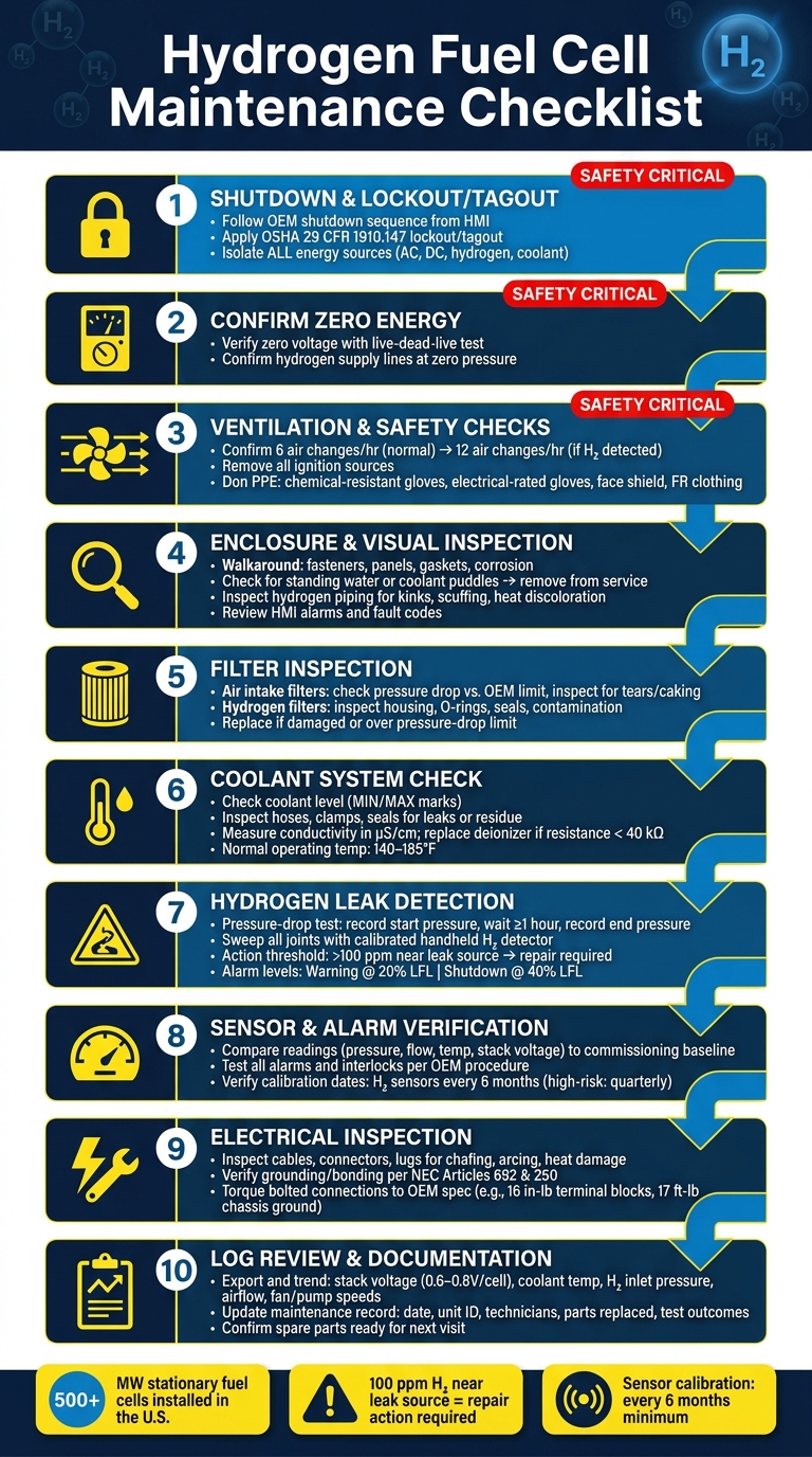
Hydrogen Fuel Cell Maintenance Checklist: Step-by-Step Service Flow
Hydrogen Fuel Cell Thermal Management | Temperature Control for Maximum Efficiency & Lifespan
sbb-itb-501186b
1. Safety preparation and pre-service shutdown
Use this step on every service call before you open any panel, line, or connector. Don’t begin until the system is shut down, locked out, and confirmed de-energized.
Verify shutdown, lockout/tagout, and zero-energy state
Start with the manufacturer's normal shutdown sequence from the HMI or control panel. Then confirm the system has come to a complete stop and wait through the OEM-specified cool-down period.
When cool-down is done, apply lockout/tagout under OSHA 29 CFR 1910.147. Isolate every energy source: the main AC feed, DC outputs, auxiliary batteries or capacitors, hydrogen supply lines, and any compressed air or coolant circuits that may still hold pressure. Put an individual lock and tag in place for each worker on site.
Next, use a calibrated meter rated for the system to verify zero voltage with a live-dead-live test. Check pressure gauges too. Hydrogen supply lines need to read zero, or the manufacturer's stated safe residual level, before you crack open any fittings.
Once zero energy is confirmed, move on to the visual, filter, and coolant checks.
Confirm ventilation, hydrogen safety, and PPE
Ventilation comes first before any hands-on work starts. In indoor service areas, make sure ventilation is on, with fresh air inlets near floor level and exhaust outlets at the highest point. Maintenance facilities for hydrogen-fueled equipment are often set at 6 air changes per hour during normal operation, then switch to 12 air changes per hour if hydrogen is detected. If ventilation drops out or an alarm goes off, stop work at once.
After airflow is confirmed, remove ignition sources from the area. That means no open flames, no non-rated tools or equipment, and no grinding or abrasive work in the service space.
Wear the required PPE:
- Chemical-resistant gloves
- Electrical-rated gloves and tools until de-energized
- Safety glasses or a face shield
- Site-required flame-resistant clothing
Also check that extinguishers are easy to reach, shutoff points are known, and evacuation routes are clear.
After shutdown is verified, move to enclosure, filter, and coolant checks.
2. Routine inspection checklist: visual checks, filters, and coolant
Inspect enclosure condition, hoses, piping, and status warnings
Start with a full walkaround before you touch anything else. Look for loose fasteners, cracked panels, corrosion, impact damage, and vibration marks near mounts. Doors and access panels should open and close without sticking, and gaskets should be intact. If you spot any gap that could let in water, dust, or debris, fix it before startup.
Check the base of the enclosure for standing water or coolant puddles. Treat either one as a remove-from-service condition. Find the source and fix it before the unit goes back into service. At the same time, scan the full accessible length of the hydrogen piping. Watch for scuffing, kinks, flattened sections, or any place where a line rubs against a metal edge or cable tray. Exposed braid, cuts, or heat discoloration also mean remove from service.
Review the HMI in the OEM-defined service mode. Do not re-energize the system unless the manual says you should. Check for active alarms, warning messages, status icons, and fault codes. Make sure fan and pump indicators match expected conditions. Log each alarm by code, description, timestamp, system ID, date, and initials. If the same alarm keeps showing up, escalate it.
If you find any leak, alarm, or damage, stop there and fix it before moving on to filters and coolant.
Check air and hydrogen filters
For air intake filters, inspect for dirt loading, dust caking, collapsed pleats, tears, and bad frame seals. Check the pressure-drop reading from the differential-pressure gauge or the HMI, then compare it with the OEM maximum limit. Replace the filter early if it is damaged, heavily loaded, or over the pressure-drop limit.
For hydrogen filters, inspect the housing for external leaks, corrosion, and seal condition. O-rings should show no cracking or chemical attack. Check the hydrogen filter for contamination and replace it when pressure drop, debris, or leak detection shows it needs service. A sudden change in upstream or downstream pressure, or activation of a hydrogen leak detector near the housing, is an immediate service trigger. Log the component ID and pass/fail result, and record the date in MM/DD/YYYY format.
Review coolant level, leaks, and conductivity
Check the coolant level in the reservoir or expansion tank against the MIN/MAX marks. Follow OEM guidance on whether the reading should be taken cold or after a run. Record the ambient temperature in °F, the system state, and any volume added, including coolant brand and amount in quarts. If you keep topping it off between scheduled services, flag it for leak detection follow-up.
Inspect all accessible hoses and clamps for dampness, dried residue, rust near clamp areas, and staining on nearby surfaces. Around pumps and heat exchangers, look for weeping at mechanical seals, corrosion at fittings, and crystalline deposits near joints. Listen for cavitation from the pump, such as rattling or grinding, and feel for abnormal vibration that may point to bearing wear or a partial blockage.
Check coolant conductivity in µS/cm and follow the OEM limit. Replace deionizer media when conductivity is over the threshold or resistance drops below 40 kΩ. Record the measured value, the instrument used, and any corrective action taken. Record the date too, so you can track trends across service intervals.
If top-offs are frequent or conductivity starts drifting, move next to leak detection and sensor checks.
| Check item | Pass criteria | Fail / action required |
|---|---|---|
| Air intake filter | Intact media, pressure drop within OEM limit | Damage, oiliness, or pressure drop over limit → replace |
| Hydrogen filter housing | No leaks, seals intact, pressure drop normal | Leak detector activation or high differential pressure → isolate and service |
| Coolant level | Within MIN/MAX band at the correct system state | Below MIN or repeated top-ups → investigate for leak |
| Coolant conductivity | Within OEM limit | Above OEM limit or low resistance → replace deionizer media |
| Hoses and clamps | Firm, flexible, no residue or damp spots | Cracking, seepage, or clamp rotates by hand → tighten or replace |
3. Leak detection, sensors, and electrical connection checks
Once filters and coolant check out, move to leaks, sensor drift, and loose electrical connections before you power the system back up.
Perform hydrogen leak and pressure checks
Hydrogen has no smell and spreads fast, so this step depends on calibrated test gear, not guesswork.
Use a pressure-drop test only when the OEM says it’s allowed. Write down the starting pressure, wait at least one hour, and record the reading again. If the pressure drops more than expected, treat that as a leak signal and track down the source before the unit goes back into service.
After that, sweep all joints, fittings, valves, regulators, quick-connect couplings, and any service ports opened during maintenance with a calibrated handheld hydrogen detector. Keep the probe close to each joint, but don’t let it touch hot surfaces or moving parts. Any reading above 100 ppm near a leak source calls for corrective action. If the manufacturer and site procedure clearly allow it, use an approved leak-detection solution such as Snoop on accessible fittings and watch for bubbles.
| Method | Tools needed | Best use case |
|---|---|---|
| Pressure-drop (decay) test | Pressure gauge or transducer, timer | System-wide check during routine service |
| Handheld hydrogen detector | Calibrated portable "sniffer" | Finding the source of a suspected or confirmed leak |
| Leak-detection solution (e.g., Snoop) | Approved foam/bubble solution, brush | Visual check at accessible joints after a leak is suspected |
Record the test method, starting and ending pressure, elapsed time, ambient conditions, and any corrective action taken.
Review sensors, alarms, and calibration status
Compare each sensor reading - pressure, flow, temperature, tank level, and stack voltage - against the commissioning baseline. If something looks off, don’t assume the sensor itself has failed. Check wiring and contamination first, then decide whether recalibration or replacement is needed.
Verify alarms and interlocks with the manufacturer-approved test procedure. Make sure high-pressure, low-pressure, overtemperature, and hydrogen detection events each trigger the right local and remote response, including any automatic gas shutoff or power disconnection. Also note whether alarm reset is manual or automatic, since that changes the return-to-service process. Hydrogen detectors often use staged trip points, such as warning at 20% LFL and shutdown at 40% LFL.
Check the last calibration date and the next due date for every sensor. Hydrogen sensors are often recalibrated every 6 months, while higher-risk areas may need quarterly checks. Log the sensor ID, measured value, calibration status, and any corrective action taken.
Inspect cables, connectors, grounding, and torque points
Inspect all accessible cables, connectors, lugs, and strain reliefs. Look for chafed insulation, cracked jackets, heat discoloration, moisture ingress, loose locking tabs, and any sign of arcing. If cable routing is rubbing metal or running too close to heat, fix it before re-energizing.
Check grounding and bonding with a visual inspection and an ohmmeter continuity test, following NEC Articles 692 and 250. Bad grounding can lead to sensor noise, nuisance faults, or a safety risk in a hydrogen setting.
For bolted connections, use the manufacturer’s torque values. OEM service data examples include 16 in-lb for terminal blocks, 17 ft-lb for air compressor chassis grounding, and 8.85 ft-lb at the fuel cell grounding side. Too little torque can lead to heat and intermittent faults. Too much can damage threads or terminals. Record the torque value, the tool used, and a pass/fail result for each connection point.
Once electrical integrity is confirmed, compare the service findings against the baseline logs.
4. Data log review, parts readiness, and maintenance records
After electrical and leak checks, finish with log review and service readiness.
Review performance logs and compare to baseline
Once the electrical checks are done, review the latest logs against the baseline. Trends matter more than one-off readings. That’s how you spot drift, instability, and wear before they turn into bigger problems.
Export data for stack voltage, output current, coolant temperature, hydrogen inlet pressure, airflow, and pump and fan speeds. For baseload systems, a detailed log review at least once a month is a practical standard. For mission-critical units, review logs after every alarm or corrective maintenance event.
| Parameter | Typical normal range | Abnormal trend |
|---|---|---|
| Stack voltage (per cell) | 0.6–0.8 V at rated load | Gradual month-over-month decline at constant load; sudden dips during stable pressure |
| Coolant temperature | 140–185 °F (steady-state) | Repeated excursions near protective limits; slow stabilization after load changes |
| Hydrogen inlet pressure | Per OEM spec (psi) | Progressive downward drift under constant supply; erratic oscillations at specific flow rates |
| Airflow | Per design at given load (scfm) | Declining flow at constant fan speed; increasing fan speed needed to maintain the same flow |
| Pump and fan speeds | Per baseline curves (RPM or % duty) | Steadily rising speed for the same load and temperature, indicating wear or blockage |
Alarm review should be just as structured. Sort alarms by type, frequency, and time. If the same alarm keeps showing up around the same condition, treat that as a red flag - especially when the logs show the same pattern alongside it.
Verify spare parts, test tools, and documentation
Use the log review to figure out what the next visit will need. It’s a simple step, but it saves wasted time on-site.
Before any scheduled service, confirm these consumables are available:
- Replacement air and hydrogen filters
- OEM-compatible coolant
- Deionization or ion-exchange cartridges
- Leak-detection supplies
Also check that the calibrated test tools required by the system are present.
Make sure the parts, tools, and records for the next service visit are ready before work begins.
Then update the maintenance record with the date and time, unit ID, technicians, parts replaced, measured results, and test outcomes. Good records do more than document the visit. They help turn service notes into early warnings, so teams can plan repairs instead of getting blindsided by emergency work.
Conclusion: A repeatable checklist for safety, uptime, and service planning
This checklist keeps service repeatable, safe, and on schedule. Each step supports safety, uptime, and steady service quality. Ventilation and leak checks matter because hydrogen is invisible, odorless, and flammable across a broad range. That means measured checks beat assumptions every time. Once those controls are in place, the checklist becomes a standard your team can use the same way, visit after visit.
Preventive maintenance only works when the same steps happen every time. A repeatable checklist is what turns routine service into predictable uptime. And that kind of consistency depends on one thing: every visit needs to be tracked against the same baseline.
Documentation ties one service visit to the next. It gives each visit a clear starting point and makes the next one easier to plan. If the checklist points to replacement gear, Electrical Trader can help source breakers, transformers, and related power distribution parts. With records in place, the checklist stays current and usable across service intervals.
The core structure - shutdown, safety, inspection, service, verification, and documentation - should stay the same. Change the checklist only when field data or OEM revisions call for it. That keeps parts, service intervals, and baseline records lined up with what the system - and each service visit - actually shows.
FAQs
How often should a hydrogen fuel cell be serviced?
Service intervals depend on the system and how it's used. Many balance-of-plant components need attention every 2,000 to 4,000 hours. Then, at around 8,000 to 12,000 hours, they usually need more extensive maintenance.
Leak detection sensors often need calibration every 3 to 6 months. In critical facilities that use backup power, NFPA 110 calls for monthly load tests and annual system testing. Always follow the manufacturer's guidelines.
What should I do if a hydrogen leak is detected during maintenance?
If a hydrogen leak is detected, the system should automatically shut off the hydrogen supply. Use integrated safety systems and fixed gas detection, because hydrogen is colorless and odorless and can't be found without specialized equipment.
Document the leak, the corrective actions taken, and the results of any follow-up verification tests in your facility's maintenance logs for safety and compliance.
Which readings matter most when reviewing fuel cell performance logs?
Focus on readings that show system health and day-to-day operation. That includes:
- Coolant level and temperature
- Gas and safety sensor readings, with extra attention on hydrogen leak detector readings and any calibration or sensitivity checks
- Electrical connection behavior, voltage, and current
- Fault or error logs
It also helps to review run-time data against baseline conditions so you can spot trends over time, not just one-off readings.