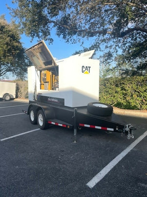
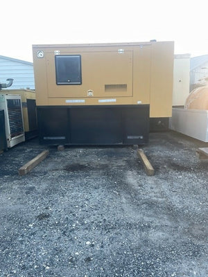
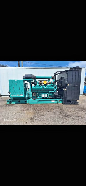
Fuel Supply Planning For Generator Installation
Most generator fuel problems start before the unit ever runs. I’d sum this up in one line: match fuel use, tank size, piping, access, and testing before installation starts.
If I were planning this job, I’d focus on four things first:
- Load and runtime: A generator burning 12 gal/hr for 72 hours needs 864 gallons of fuel before tank-use limits and margin are added.
- Tank setup: A sub-base tank often works for about 8–24 hours, while longer runtimes often need a day tank plus remote bulk tank.
- Location and piping: Tanks need room for fuel delivery, service access, vents, shutoffs, and fire spacing.
- Startup and records: I’d test leaks, alarms, pump controls, and load performance before handoff.
A few numbers matter right away:
- Only about 90% of a tank’s listed volume may be usable.
- Indoor fuel storage in a shared generator room is often capped around 660 gallons.
- Sites with more than 1,320 gallons of aboveground oil storage may need an SPCC plan.
- Fuel system issues are a leading cause of generator no-start events in hospitals.
Here’s the short version: start with expected load, convert that into hourly fuel burn, size the tank for the target runtime, then confirm placement, piping, and testing rules on paper before the install begins. That approach helps you avoid short runtime, hard-to-fill tanks, blocked service access, and failed inspections.
Checklist 1: Calculate Fuel Demand and Required Runtime
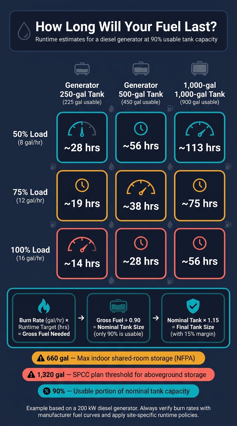
Generator Tank Runtime: Load vs. Tank Size Comparison Chart
Before you install anything, size fuel storage based on the load you expect to run and how long you need the generator to stay online. This checklist walks through load confirmation, fuel burn lookup, and tank sizing in U.S. units: kW, gallons, and hours.
Confirm Load Type, Duty Cycle, and Fuel Burn Rate
Start with the actual load the generator will carry, along with its duty cycle: standby, prime, or continuous. That part matters because each load type calls for different fuel sizing. From there, use the manufacturer's fuel curve at the load you expect in normal use.
For a diesel standby generator in the 150–200 kW range, fuel use is often about 6–8 gal/hr at 50% load and 10–13 gal/hr at 75% load. It also makes sense to add a 10% planning margin on top of the published burn rate to cover load swings and startup fuel use.
Convert Runtime Targets into Minimum Tank Capacity
Once you have the burn rate, the math is simple: fuel burn (gal/hr) × target runtime (hours) = gross fuel needed.
Here’s the example from above: a 200 kW generator running at 75% load and burning 12 gal/hr would need 864 gallons for 72 hours of runtime. And 72 hours is a common planning target.
But gross fuel needed is not the same as tank capacity. In practice, you won't use every gallon in the tank. Bottom dead zones, pickup height, and sediment usually mean only about 90% of nominal tank capacity is usable. So divide the gross fuel need by 0.90 to find the minimum nominal tank size. After that, add a 10% to 15% planning margin for contingency.
Using the same example:
- 864 ÷ 0.90 = 960 gallons nominal
- 960 × 1.15 = 1,104 gallons
That points you to a standard 1,100-gallon or 1,200-gallon tank.
Load vs. Runtime Comparison Table
The table below gives a quick side-by-side look at runtime across common tank sizes. It uses an example diesel generator with published burn rates of 8 gal/hr at 50% load, 12 gal/hr at 75% load, and 16 gal/hr at 100% load. Usable fuel is based on 90% of nominal tank capacity.
| Load (%) | Fuel Burn (gal/hr) | 250-gal Tank (225 gal usable) | 500-gal Tank (450 gal usable) | 1,000-gal Tank (900 gal usable) |
|---|---|---|---|---|
| 50% | 8 | ~28 hrs | ~56 hrs | ~113 hrs |
| 75% | 12 | ~19 hrs | ~38 hrs | ~75 hrs |
| 100% | 16 | ~14 hrs | ~28 hrs | ~56 hrs |
Size the tank to the expected load, not the nameplate rating, and check the result against the facility's minimum runtime policy. Use that fuel demand number to pick the tank size and location in the next checklist.
sbb-itb-501186b
Checklist 2: Choose Tank Configuration, Location, and Access
Once fuel demand is set, the next step is choosing a tank setup that fits the site and stays within fire and spill rules. That decision affects everything around it: where the fill point goes, how piping runs, and how crews will reach the equipment for service.
Select the Tank Setup That Fits Runtime and Site Limits
A sub-base (integral) tank is a good fit for standby generators that need about 8–24 hours of runtime. It keeps the generator and fuel supply in one footprint, which can save space. In many cases, it also includes built-in secondary containment. The tradeoff is simple: capacity is limited by the generator frame and by required clearances.
If the project needs more runtime than a sub-base tank can handle, the usual setup is a day tank plus remote bulk tank. The day tank is often sized for about 1–2 hours of runtime and refills automatically from a larger tank located somewhere else on the site. This layout makes sense when runtime goes beyond sub-base limits, or when the generator sits indoors, on a roof, or in a tight area where a larger tank just won't fit.
NFPA-based guidance often limits fuel stored in a shared generator room to 660 gallons. Once you go above that, the tank should be in a dedicated fire-rated room with 1-hour construction and about 36 inches of service clearance.
For larger fuel volumes, an outdoor aboveground storage tank feeding an indoor day tank is often the most practical arrangement. There is also an EPA SPCC angle here. Any single aboveground container over 660 gallons counts toward the facility threshold, and sites with more than 1,320 gallons total aboveground need an SPCC plan plus secondary containment sized for 110% of the largest tank's volume.
Once you've picked the tank type, placement becomes the next big call.
Check Tank Location, Fill Point Access, and Inspection Clearance
Tank placement should keep the day tank or integral tank close to the generator while still leaving enough room for fire separation and service work. Manufacturer guidance usually recommends keeping the tank within about 65 ft and on the same level. That helps avoid air in the fuel line and cuts down on priming problems.
It also helps to plan for fuel delivery early, not at the end when the site layout is already locked in. A marked delivery bay with bollards, a lockable fill cabinet, and clear hose access can prevent a lot of headaches. Just as important, the hose route should not block emergency paths.
For outdoor bulk tanks, NFPA 30 spacing depends on tank size. A practical rule of thumb is that tanks up to 12,000 gallons should be at least 5 ft from a building, street, or sidewalk, while property-line setbacks often fall between 5 ft and 15 ft based on tank size. It’s also smart to check that the tank does not interfere with doors, windows, fresh air intakes, emergency exits, or fire department access routes.
Leave 36 inches of clear working space around gauges, leak detection, overfill protection, and emergency shutoff valves. Put those clearances in the construction documents from the start. If you treat them like an afterthought, they often disappear once walls, curbs, and piping show up.
Indoor vs. Outdoor Tank Comparison Table
| Factor | Indoor Tank | Outdoor Tank |
|---|---|---|
| Capacity limits | Often limited to 660 gallons in a shared generator room; larger volumes require a dedicated, fire-rated room | Usually allows larger capacities, but SPCC thresholds may apply to aboveground storage |
| Ventilation | Requires mechanical or natural ventilation to manage flammable vapors | Open-air location helps with ventilation, though vent design still needs to keep out rain, insects, and ice |
| Weather exposure | Protected from UV, precipitation, and temperature swings; freeze protection is easier | Needs corrosion protection, insulation or heat tracing in cold climates, and secure anchorage |
| Fuel truck access | Access can be limited; hose routing through the building may be difficult | Direct truck access is often easier; a dedicated delivery bay with bollards is common |
| Spill containment | Spill containment is inside the building, which can add to fire loading | Usually needs secondary containment such as a double-wall tank, dike, or vault |
| Inspection access | Good lighting and a controlled setting, but tight mechanical rooms can restrict access | More open space for large components, though weather and site conditions can make access harder |
With tank type, location, and access set, the next step is routing the supply, return, vent, and transfer lines around that layout.
Checklist 3: Plan Fuel Piping Route, Transfer Equipment, and Fire Separation
Map Supply, Return, Vent, and Transfer Paths Before Installation
Once the tank location is locked in, map every fuel path before anyone starts trenching or cutting through walls. Put the full layout on paper first. Mark the supply, return, vent, and transfer routes from the bulk tank to the day tank and generator. Include elevation changes, wall penetrations, and support points.
The goal is simple: keep runs short and direct. Avoid hidden piping in walls or ceilings that people can’t reach later. Extra bends and dead-end branches can hold fuel in place, and that can lead to internal corrosion over time.
If piping has to pass through occupied areas, use double-wall or jacketed steel piping with welded connections. Add leak detection at low points too. Keep fuel lines away from exit paths and traffic lanes. Where lines cross vehicle routes or material handling areas, protect them from impact. Elevation changes matter here as well. Poor routing can create air pockets and vapor lock, so lay out supports and hangers to limit vibration and reduce the risk of fatigue failures.
Return piping needs just as much attention as supply piping. Diesel injection pumps often send 30% to 50% of total fuel flow back through the return line as bypass fuel. That’s why return lines are usually sized about the same as the supply line, or at least one pipe size smaller. Also, don’t put shutoff valves in return piping.
For sites with more than one generator, give each unit its own supply and return lines. That keeps idle sets isolated from return pressure. Return lines should enter tanks from the top and end above the fuel level, which helps cut down turbulence and foaming.
Vent piping has its own set of rules. Normal and emergency vents need to terminate outside the building at least 12 ft above grade, 5 ft from openings or property lines, and 15 ft from air intakes. Use weatherproof caps. If a sub-base tank sits inside a generator enclosure, the atmospheric vent still has to exit the enclosure. The emergency vent may terminate inside the enclosure.
Confirm Fire Separation Distances and Safety Controls
Fire separation doesn’t stop at the tank. It also applies to piping, vents, and connected equipment.
UL 142 tanks need separation distances from buildings, property lines, and public ways based on tank size. UL 2085 tanks can often use smaller setbacks because their protected construction gives them more fire resistance. If space is tight or the tank sits near a property line, a UL 2085-listed tank can give you more room to work with than a standard UL 142 tank.
Keep fuel piping clear of exhaust parts, turbochargers, and other hot surfaces. If piping runs near ignition sources, install spray shields. Emergency shutoff valves should be easy to reach and clearly labeled near the generator and day tank. When possible, place them outside the main fire exposure zone. Tie overfill alarms and high-level sensors into the generator control system or the building management system so operators get a warning before a spill happens.
Once the routing and separation plan is in place, verify the full setup during commissioning.
Remote Bulk Tank Plus Day Tank vs. Sub-Base Tank Only: Comparison Table
| Factor | Remote Bulk Tank + Day Tank | Sub-Base Tank Only |
|---|---|---|
| Runtime capacity | High - bulk tanks can be sized in the hundreds to thousands of gallons, while the day tank provides several hours of runtime near the generator | Limited by generator frame size; typically supports 8–24 hours of runtime |
| Piping complexity | Higher - requires transfer pumps, supply and return lines between tanks, vents, overfill lines, and control wiring | Lower - short supply and return connections and vents; most piping stays within the generator skid footprint |
| Fuel delivery | Bulk tank can be placed with dedicated truck access and metered fill points; day tank refills automatically through level-sensor-controlled transfer pumps | Fuel delivery must reach the generator location directly, which can be difficult in tight mechanical yards or near building entrances |
| Inspection access | More components to check, including transfer pumps, controls, multiple tanks, and longer piping runs, although the bulk tank area is often easier to access safely | Fewer components, but bottom surfaces and concealed areas beneath the generator frame can be harder to inspect thoroughly |
| Use when | Hospitals, data centers, and industrial plants needing 48–96+ hours of fuel autonomy or high fuel consumption rates | Small offices, light commercial buildings, or sites where a few hours of runtime is sufficient and installation simplicity is the priority |
Checklist 4: Commission the Fuel System and Document Compliance
After the piping is in, the tank is set, and the fire separation work is done, commission the fuel system before turnover.
Verify Installation, Startup Testing, and Alarm Operation
Before handoff, inspect tank seams, pipe joints, flexible connectors, valves, filters, and wall or slab penetrations for leaks or damage. If the system uses double-wall piping or leak detection, check that the sensors respond and record the alarm status.
Record the starting fuel level and make sure the gauge, remote monitor, and level alarms all match. That first reading gives the maintenance team a baseline for future fuel-use checks and leak detection.
Next, bleed and prime the lines, then start the generator and load-test it based on the project plan. For a new EPSS, run the NFPA 110 acceptance test with all accessories operating, using building load or a load bank to reach nameplate kW. Use the automatic transfer switch to simulate a utility outage during the test.
While the system runs, watch for common trouble signs:
- Pressure swings
- Pump cycling problems
- Air in the lines
- Delayed startup
- Nuisance alarms
- Fuel starvation
Also confirm that transfer pumps start and stop at the right setpoints and that any redundant pumps respond the way the design calls for.
Before handoff, test low fuel, high fuel, pump failure, leak detection, and vent or pressure alarms. Then verify that remote annunciation reaches the generator controller, building management system, and any off-site monitoring platform.
Record Inspection Items, Code References, and Maintenance Intervals
Once startup testing is complete and the system passes, add the results to the turnover package.
Give the AHJ and the maintenance team the as-builts, cut sheets, startup and leak-test reports, alarm test results, inspection logs, maintenance instructions, and code references. Notify the AHJ early so it can witness the acceptance test.
The maintenance team should also get a short operating summary with the tank type, fuel type, fill location, shutoff locations, alarm setpoints, and service intervals. For diesel systems, schedule fuel testing at least twice a year, with no less than 6 months between tests.
Use the turnover package as the baseline for later maintenance.
| Interval | Check |
|---|---|
| Weekly | Visual walkaround; verify fuel level, oil, coolant, batteries, and alarms |
| Monthly | Run the generator for at least 30 minutes at 30% or more of nameplate kW; operate each automatic transfer switch |
| Semiannually | Test fuel quality for degradation, water, and sediment |
| Periodic | Inspect valves, vents, pumps, piping, and logs per manufacturer and site requirements. |
Fuel system failures are the largest single category of generator non-start events in hospitals. That’s why clean records matter. A clear log of what was tested, what passed, and when the next check is due gives the facility team something they can actually use during turnover, troubleshooting, and future inspections.
Conclusion: Review the Fuel Supply Planning Checklist
Commissioning confirms leak-free fuel delivery, successful load testing, and working alarms.
FAQs
How do I estimate runtime accurately?
Use the manufacturer’s spec sheet to find fuel use in gallons per hour (GPH) at 25%, 50%, 75%, and 100% load. If that data isn’t listed, use a simple fallback: 0.1 gallons per hour per kilowatt of output.
Then multiply the burn rate by your planned runtime in hours. After that, add a 5% to 20% safety margin to cover site conditions, engine wear, and fuel you may not be able to use at the bottom of the tank.
When should I use a day tank?
Use a day tank when the main fuel tank sits below the engine or is too far away for the generator’s fuel pump to pull fuel on its own.
A day tank works as an in-between fuel reservoir. It helps keep fuel flow steady, supports stable fuel pressure, collects returned fuel so heat can dissipate, and manages fuel volumes that go beyond indoor storage limits.
What codes should I verify first?
Start by checking NFPA 30 for flammable liquid storage and the OSHA rules that apply to safety parts like flame arrestors and pressure-relieving vents.
Then look at your local code. In many cases, local rules are stricter, especially when total fuel volume goes up. They also spell out limits like the 25-gallon indoor cap for Class I flammable liquids and the distance required between stored fuel and ignition sources.