




HV Cable Testing Standards Guide: IEC, IEEE, UL
If you mix up IEC, IEEE, and UL, you can approve the wrong cable, miss a bad installation, or accept weak paperwork. In simple terms: IEC covers design and factory tests, IEEE covers field tests on installed cable systems, and UL covers U.S. listing records.
I’d boil the article down to this:
- IEC tells me what the cable system was built and qualified to do
- IEEE tells me whether the installed system passed field checks
- UL tells me whether the product record matches U.S. listing needs
- One record does not replace the others
- Cable, joints, and terminations should be checked as one system
- Factory paperwork alone is not enough, especially when a 2024 IEEE workshop study tied 57% of HV cable failures to workmanship defects and 16% to manufacturing defects
If I’m buying or approving HV cable, I’d ask three direct questions right away:
- Which IEC standard fits the cable voltage class?
- Which IEEE field test record proves the installed circuit passed?
- Does the UL file and marking match the exact product shipped?
For voltage class, the article says to stop using loose labels like “MV” or “HV” and check the U₀/U(Um) rating instead. For field work, it points to IEEE 400-2023 for installed shielded power cables rated 5 kV and above. For U.S. buying records, it says to verify the UL Listing Mark, file number, and Product iQ status, not just a brochure or jacket print.
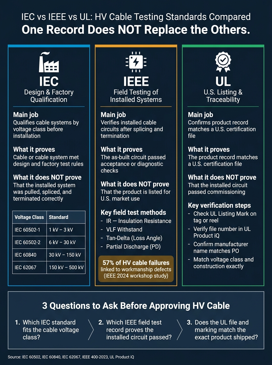
IEC vs IEEE vs UL: HV Cable Testing Standards Compared
Cable Testing Standards Overview of the IEEE 400 Bundle youtube
sbb-itb-501186b
Quick comparison
| Standard | Main job | What it proves | What it does not prove |
|---|---|---|---|
| IEC | Design, construction, factory qualification | The cable or cable system met design and factory test rules | That the installed system was pulled, spliced, and terminated correctly |
| IEEE | Field testing of installed cable systems | The as-built circuit passed acceptance or diagnostic checks | That the product is listed for U.S. market use |
| UL | Listing and traceability | The product record matches a U.S. certification file | That the installed circuit passed commissioning |
The article then walks through the voltage ranges for IEC 60502-1, IEC 60502-2, IEC 60840, and IEC 62067, the main IEEE field methods like IR, VLF, withstand, tan-delta, and PD, and the records buyers should ask for before purchase or energization.
If I had to sum it up in one line: match the standard to the job, then match the paperwork to the question you need answered.
IEC Cable Scope and Voltage Classes
Start with the cable’s rated voltage and where it will be installed. That tells you which IEC standard applies. Don’t lean on labels like “MV” or “HV.” Instead, check the U₀/U(Um) rating on the nameplate or datasheet: U₀ is conductor-to-earth voltage, U is conductor-to-conductor voltage, and Um is the maximum system voltage.
Here’s how each IEC part lines up with voltage range:
| Standard | Voltage Range | Scope |
|---|---|---|
| IEC 60502-1 | 1 kV and 3 kV | Extruded solid-insulation cables |
| IEC 60502-2 | 6 kV to 30 kV | Extruded solid-insulation cables |
| IEC 60840 | Above 30 kV to 150 kV | Cable systems, including accessories |
| IEC 62067 | Above 150 kV to 500 kV | Cable systems, including accessories |
IEC 60502-1 and IEC 60502-2: Low- and Medium-Voltage Ranges
IEC 60502-1 applies to power cables with extruded solid insulation rated at 1 kV and 3 kV for fixed installations, including distribution networks and industrial installations. Common rated voltage designations include 0.6/1 kV and 1.8/3 kV. The standard sets rules for conductor type, insulation thickness, sheath construction, and the routine and type tests a cable must pass before it leaves the factory.
IEC 60502-2 covers the same extruded-insulation build, but for 6 kV up to 30 kV. Standardized ratings include 3.6/6 kV, 6/10 kV, 8.7/15 kV, 12/20 kV, and 18/30 kV. These cables are common in plant and utility MV distribution. One important limit: do not use IEC 60502-2 for overhead, mining, nuclear, submarine, or shipboard cables.
Once the IEC voltage class is nailed down, the next step is checking how installed cables are tested in the field.
IEC 60840 and IEC 62067: Higher-Voltage Cable Systems
At transmission voltages, the rules get stricter. IEC 60840 applies to power cable systems above 30 kV up to 150 kV, while IEC 62067 covers systems above 150 kV up to 500 kV. These standards do not treat the cable as a stand-alone item. They treat the cable, joints, and terminations as one system, tested and qualified together.
That point matters in practice. If a joint or termination does not have system-level qualification, the project record is not compliant under these standards. In plain terms, a cable-only test report is not enough for a 60840 or 62067 job if it leaves out accessory qualification.
For transmission-class cables, ask for system-level type test certificates that match both the IEC standard and the voltage class. Also, watch for submarine and other special installations. Both standards note that these cases may need modified test conditions, so it’s smart to flag them early rather than sort it out later in the project.
Installed systems then move to IEEE field testing and acceptance checks.
IEEE Field Test Methods for Installed HV Cable Systems
IEEE 400-2023 lays out how shielded power cable insulation should be tested in the field for installed systems rated 5 kV and above. It covers the main test methods, what each one can show, and where each method falls short. In plain English, IEEE is the field-side match to the IEC factory framework covered earlier.
One point matters a lot here: the cable, joints, and terminations are tested as one system - not just the cable by itself. So if a record shows testing on the cable only and leaves out the accessories, it does not describe the condition of the full installed system.
| Test Method | What It Shows | When Buyers Should Expect the Record |
|---|---|---|
| Insulation resistance (IR) | General insulation integrity; identifies major insulation defects | Commissioning or maintenance reports, before energization |
| Withstand testing (DC or VLF) | Overall withstand performance; does not locate defects | Acceptance documentation and post-repair records |
| VLF withstand / diagnostic | Overall insulation strength; can be paired with tan-delta or PD for deeper assessment | VLF commissioning, acceptance, or periodic maintenance reports |
| Partial discharge (PD) | Localized defects in cable accessories | Diagnostic packages for service-aged circuits or specified pre-energization acceptance |
The next job is figuring out which field method matches the circuit’s condition and the kind of acceptance record you need.
Insulation Resistance and Withstand Testing
Insulation resistance (IR) testing is usually the first stop in a field check. A DC megohmmeter is applied conductor-to-ground and conductor-to-conductor, and the results are reported in megohms or gigohms. Project specs often set minimum pass levels. For example, they may call for 1,500 MΩ for 5 kV cable and 5,000 MΩ for 15 kV cable, along with notes on temperature, test time, and how the reading stabilized.
IR testing is good at showing whether there’s major contamination, moisture, or a gross insulation failure at the moment of testing. But it has blind spots. It won’t pinpoint a defect, single out a bad joint, or show early partial discharge activity. Think of IR as a quick health check, not the whole medical chart.
Withstand testing takes things further by applying voltage above normal operating stress for a set period to see whether the insulation holds. DC withstand, covered in IEEE 400.1, is used mainly for laminated dielectric systems such as paper-insulated cables. For extruded XLPE or EPR cables, which are common in U.S. medium-voltage work, VLF AC withstand under IEEE 400.2 is the more common choice.
A withstand test gives a simple pass/fail answer. It shows whether the insulation can survive the test voltage at that point in time. What it does not do is tell you where a defect is or how bad it may be.
Very Low Frequency and Partial Discharge Testing
VLF testing works well in the field because 60 Hz AC test sets are often too large and power-hungry to use in a practical way. IEEE 400.2 treats VLF as both a withstand method and a diagnostic method. A common acceptance test for a new cable circuit runs at 0.1 Hz for 60 minutes. On an aged circuit, a maintenance withstand test usually runs for 30 minutes at the same frequency.
When VLF is paired with tan-delta (loss angle) measurements, it can show water treeing, dielectric aging, and broader insulation degradation. That’s why VLF records often include more than just “passed” or “failed.” Buyers may also see the withstand level, test duration, and tan-delta baseline or tip-up values.
Partial discharge (PD) testing, covered in IEEE 400.3, goes a step further. PD can reveal voids, protrusions, contamination, and defects in joints and terminations that IR and basic withstand tests can miss completely. This is not just a yes-or-no test. A PD report may include:
- Apparent charge in picocoulombs (pC)
- Discharge inception and extinction voltages
- Location data
That kind of record helps show defect location, severity, and likely accessory trouble points. For buyers and asset managers, that’s a lot more useful than a simple withstand result when the goal is to judge system condition and plan next steps.
These field records feed the acceptance and insulation checks that buyers review next.
Acceptance Tests, Insulation Checks, and Required Evidence
Field testing tells you what shape the installation is in. This section separates the records buyers should ask for: routine, type, sample, acceptance, and diagnostic. That distinction matters because each record points to a different proof point. One shows factory output, another shows how the cable was installed, and another sets the first diagnostic baseline for the cable system.
Routine, Type, and Sample Tests from the Factory
Routine tests are production checks run on every cable length before shipment. Ask for a factory routine test report tied to the drum or reel number. Type tests are qualification tests run once on a representative design before commercial supply. Check that the insulation type, conductor size, and shield construction match the scope of the certificate. Sample tests are periodic factory checks on selected production lengths. They show that production still matches the qualified design.
| Test Category | Purpose | When Performed | Typical Document | What to Request |
|---|---|---|---|---|
| Routine test | Verify every manufactured length meets specified requirements | At factory before shipment | Factory routine test report | Reports for each delivered reel or drum, including PD and voltage-withstand results |
| Type test | Qualify the cable system design for commercial use | Once per design, before first supply | Type test certificate or report | Full documentation covering AC withstand, impulse, heating cycles, and any PD/tan delta data that apply |
| Sample test | Confirm ongoing production consistency | Periodically at factory on selected lengths | Sample test summaries | Evidence that sample testing is part of the supplier's QA program for the batch |
| Field acceptance test | Confirm installation did not introduce defects and that the circuit is ready to energize | After installation and terminations, before energization | Commissioning/acceptance report | Circuit-by-circuit reports with pass/fail criteria and test parameters |
| Diagnostic check | Assess insulation aging, moisture, and defects over service life | At commissioning baseline and periodically during service | Diagnostic report | Baseline diagnostics for critical feeders and evidence of periodic follow-up |
On Electrical Trader, ask for manufacturer-signed scans of factory reports. Then verify that the UL mark matches the stated voltage class and construction. For 69 kV and above, bring in a third party to confirm that the factory test conditions match IEC 60840 or IEC 62067.
Field Acceptance Tests and Diagnostic Insulation Checks
Factory records show production quality. Field acceptance shows whether the installed circuit made it through handling, splicing, and termination without damage. A commissioning report for an installed circuit should list the instrument, calibration date, applied voltage relative to U₀, test duration, per-phase IR values, and the pass/fail result tied to the applicable IEEE 400-series guidance.
Diagnostic checks go a step further. IEEE 400.2 reports should show mean tan delta at 1.0 × U₀, stability over time, and tip-up between test voltages. If the tip-up between 0.5 × U₀ and 1.5 × U₀ is large, that's a warning sign. It can point to defects that are localized and dependent on electrical stress.
Partial discharge diagnostics, covered under IEEE 400.3, add another layer. A good diagnostic PD report should include apparent charge in picocoulombs, partial discharge inception voltage (PDIV), extinction voltage (PDEV), and location data where available. Don't judge PD severity by pC alone. Inception and extinction voltages, pattern analysis, and trend data over time all matter.
For teams running critical feeders, the commissioning diagnostic report should be treated as a baseline, not a one-and-done file. Comparing tan delta and PD results year over year is how condition-based maintenance programs catch deterioration before it turns into an unplanned outage. Next, compare these records with UL listing evidence to confirm market acceptance.
UL Listing Evidence and How Buyers Compare Cable Records
What a UL Listing Record Should Show
After IEC defines the cable system and IEEE checks the installed circuit, UL verifies the product record buyers rely on during procurement.
A UL listing record should clearly show the exact product designation, voltage rating, construction description, and current traceability to the UL file. The listed cable also needs to match the project spec exactly, including conductor type, insulation system, shielding, jacket, and installation environment.
For UL-listed wire and cable, the UL Listing Mark on the tag, reel, flange, or smallest unit container is the main proof of certification. A UL symbol printed on the cable jacket is only extra support and should not be used by itself to confirm listing status. The label or container mark should include the UL symbol, the word LISTED, a control number or serial number, and the product category linked to the UL CCN.
Buyers should check the supplier's UL file number in UL's Product iQ directory. Make sure the record is active, the manufacturer name matches the purchase order, and the category and ratings cover the exact cable being quoted. If all you get is a brochure or a broad compliance statement, that's not enough.
Counterfeit UL marks are common in wire and cable.
Checklist for Reviewing Cable Listings and Test Documents
Use this checklist to compare the listing, factory reports, and field records line by line.
- Product designation: Does the exact cable model on the listing match the purchase order and project submittal?
- Voltage class: Does the marked voltage rating match the project requirement?
- Construction details: Do the insulation material, shielding or armor, jacket, conductor size, and conductor material match the specification line by line?
- UL certification status: Is the UL file number active and traceable in Product iQ, with the correct manufacturer name and category information?
- Supporting tests: Do the factory reports and field acceptance records match the listed product?
- Document consistency: Do the manufacturer name, model, and revision level match across the listing record, factory reports, and shipping documents?
You can use Electrical Trader to review cable listings and specs, but certification still needs to be checked separately.
Conclusion: Match the Standard, the Test, and the Record
If any document conflicts, stop there and sort it out before purchase or acceptance. Match the listing, test reports, and shipping records first.
IEC qualifies cable systems by voltage class, IEEE verifies installed circuits, and UL records product listing traceability. Buyers need all three to confirm what was ordered, installed, and accepted.
None of these replaces the others. A cable may have UL listing evidence and still need IEEE acceptance testing after installation. It may meet an IEC design standard and still need a traceable UL file number for U.S. project compliance. Buyers who compare cable systems by voltage class, test category, and document quality are in a much better spot to avoid mismatches between what was ordered, what was listed, and what was delivered and installed.
FAQs
How do I choose the right IEC standard?
First, pin down your equipment type and how it will be used. That means the installation setting, storage conditions, and any mechanical or thermal stress it may face. Then check Clause 1 (Scope) to make sure the standard applies to your equipment, voltage range, and intended use.
Next, match the asset to the right product standard. Confirm the exact standard, part number, and edition. For procurement, don’t accept “IEC compliant” on its own. Ask for full test reports that show the test method, severity, duration, and pass/fail criteria.
When is IEEE 400 field testing required?
IEEE 400 is a main reference for high-voltage cable field testing. Teams use it for formal withstand checks during commissioning, after equipment repairs, or any time the project’s governing standard requires that test.
Before you start, verify the right test level and procedure. The best way to do that is to line up IEEE 400 with the cable manufacturer’s documentation.
What documents should I verify before approval?
Before final approval, verify the full documentation package. That includes type-test certificates, factory test reports, design verification reports, and detailed insulation test records.
Those insulation records should clearly show:
- the test method
- the test voltage
- the test duration
- leakage limits
- the standard used
For used equipment, go a step further. Check the nameplate data, manuals, maintenance and inspection history, and service records.
It also helps to cross-check the basics side by side: part numbers, serial numbers, and nameplate photos. For U.S. installations, confirm that the equipment has valid NRTL certification, such as UL or CSA.





