




How Fault Detection Works in Medium Voltage Systems
Fault detection in medium voltage (MV) systems is vital for ensuring safety, protecting equipment, and maintaining reliable power distribution. These systems, operating between 600 V and 69 kV, are commonly found in utility networks, industrial facilities, and commercial buildings. Faults, such as phase-to-ground, phase-to-phase, and high-resistance faults, can disrupt operations, damage equipment, and pose safety risks. Advanced technologies like signal processing, real-time monitoring, and statistical analysis help identify and address these issues quickly, minimizing downtime and improving performance.
Key points:
- Common Faults: Phase-to-ground, phase-to-phase, high-resistance, and arcing faults.
- Detection Technologies: Signal processing (e.g., wavelet transform), Intelligent Electronic Devices (IEDs), and Linear Discriminant Analysis (LDA).
- Benefits: Faster fault identification, reduced outages, and improved maintenance through predictive tools.
- Implementation: Many utilities already have basic hardware in place, such as protection relays, which can be upgraded with modern software and monitoring systems.
Theory 4: Earth Fault Protection in Medium-Voltage Power Networks
sbb-itb-501186b
Types of Faults in Medium Voltage Systems
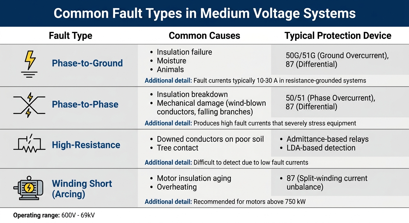
Common Fault Types in Medium Voltage Systems: Causes and Protection Devices
Common Fault Types in MV Systems
Medium voltage (MV) systems are prone to several types of faults, each with unique causes and protection requirements.
Phase-to-ground faults are among the most frequent issues in MV networks. They often result from insulation failure, moisture, or even animal interference. In resistance-grounded systems, ground-fault protection (Device 50G) is typically calibrated for fault currents between 10 A and 30 A. To limit these currents, system neutral grounding resistors are usually designed to keep the fault current within a range of 400 A to 2,000 A.
Phase-to-phase faults occur when two phases come into contact, often due to mechanical damage like wind-blown conductors or falling branches. These faults produce high fault currents that can severely stress equipment. Rapid protection, such as differential or overcurrent devices, is critical to minimize damage.
Three-phase faults, though less common, involve all three phases at once. These faults are the most severe short-circuit conditions and require immediate action to prevent catastrophic damage.
High-resistance faults (HRF) are particularly tricky to detect because they produce low fault currents. These faults can occur when a conductor contacts high-impedance surfaces like trees or poorly conductive soil. Standard overcurrent protections often fail to detect these, making admittance-based relays or LDA-based detection systems essential.
Arcing faults involve electrical discharges that can occur intermittently or continuously, often in distribution lines or motor windings. In MV motors, these can lead to short-circuited winding turns, where turns within a single phase become shorted. Split-winding current unbalance protection is highly recommended for motors above 750 kW to detect these issues. Additionally, leakage faults, such as damaged insulators, may not trigger immediate safety responses but can still be identified through signal analysis.
| Fault Type | Common Causes | Typical Protection Device |
|---|---|---|
| Phase-to-Ground | Insulation failure, moisture, animals | 50G/51G (Ground Overcurrent), 87 (Differential) |
| Phase-to-Phase | Insulation breakdown, mechanical damage | 50/51 (Phase Overcurrent), 87 (Differential) |
| High-Resistance | Downed conductors on poor soil, tree contact | Admittance-based relays, LDA-based detection |
| Winding Short | Motor insulation aging, overheating | 87 (Split-winding current unbalance) |
These fault types highlight the complexities of maintaining MV network stability and the need for precise protection strategies.
How Faults Affect System Reliability
Each fault type has unique characteristics, but they all disrupt system reliability by causing voltage sags and transients. These disturbances ripple through the network, potentially leading to power system instability. If not addressed quickly, faults can cause generators to lose synchronization, triggering widespread outages. Performance metrics like SAIDI (System Average Interruption Duration Index) and SAIFI (System Average Interruption Frequency Index) are directly impacted by these disruptions.
"The usual objective of motor-fault protection is to remove the fault before the stator iron is significantly damaged." – Edvard Csanyi, Founder, EEP
Undetected faults pose serious safety risks. For example, Ground Mat Potential Rise (GPR) can endanger personnel and damage communication circuits. Additionally, arc flashes and electrical shocks are significant hazards. In MV motors, prolonged faults can severely damage stator iron and winding insulation if not cleared promptly.
Fault detection becomes even more challenging depending on the grounding method used. Isolated or compensated networks, for instance, experience lower ground fault currents, making diagnosis more difficult compared to grounded systems. Selecting the right grounding approach and ensuring proper protection coordination are critical for maintaining both safety and operational efficiency.
Fault Detection Technologies and Methods
After understanding fault types and their effects on system reliability, let's delve into how cutting-edge detection technologies protect medium voltage (MV) networks. These methods combine signal processing, real-time monitoring, and advanced strategies to pinpoint and manage faults under various conditions.
Signal Processing Techniques
Signal processing plays a critical role in identifying irregularities in electrical waveforms. Techniques like the Discrete Wavelet Transform (DWT) break down fault currents into multiple frequency levels. By isolating low-frequency components (0–1.5625 kHz) through Level 4 approximation coefficients (A4), DWT can distinguish actual fault currents from high-frequency noise, such as that caused by line capacitance discharge, which might otherwise trigger false alarms.
Another approach, time-window analysis, segments recorded signals into "Before Damage" (BF) and "During Damage" (IN) periods. This method calculates metrics like average admittance and phase shift, creating unique fault signatures for precise identification. Similarly, the Fourier Transform analyzes phase shifts between current and voltage signals, further refining fault signature calculations.
These precise analytical tools are complemented by systems that continuously monitor network performance.
Real-Time Monitoring Systems
Real-time monitoring has evolved significantly, moving from portable tools to fully integrated systems that offer constant oversight of network health. Intelligent Electronic Devices (IEDs), installed at terminals, measure positive and negative pole currents. Using transformation matrices, these devices calculate line-mode currents while mitigating mutual coupling effects. They communicate via the IEC 61850 protocol over fiber optics, ensuring synchronized data sharing across multiple IEDs and minimizing errors.
Digital Fault Recorders (DFRs) capture both standard 50/60 Hz waveforms and transient components, such as voltage spikes. Modern DFRs support continuous oscillography streaming at 3 kHz and can record uninterrupted data for over 10 days. Meanwhile, Phasor Measurement Units (PMUs) deliver real-time voltage, current, and frequency readings at up to 120 frames per second. This capability is indispensable for spotting oscillations and disturbances.
"Continuous oscillography streaming and recording at 3 kHz... ensures that power system events are never overlooked." – SEL (Schweitzer Engineering Laboratories)
While these systems provide consistent performance tracking, advanced detection methods take fault classification and localization to the next level.
Advanced Detection Methods
Settingless algorithms stand out by operating without fixed thresholds. Instead, they assess the rate of change in current differences between local and remote terminals. This flexibility allows them to detect high-impedance faults (up to 200 Ω) in as little as 0.25 milliseconds.
Another innovative approach is Linear Discriminant Analysis (LDA), which uses statistical methods to classify fault types and estimate ground fault distances based on signal patterns. In a 2022 study by Bialystok University of Technology and Elektrometal Energetyka S.A., an LDA-based system for 15 kV MV lines achieved 98.6% accuracy in locating faults on unbranched lines and 85.6% accuracy on branched networks. This research, co-funded by the European Union, also demonstrated LDA's ability to identify network configurations - whether isolated, compensated, or grounded - with near-perfect precision.
Lastly, Energy Packet Technology offers a solution for measuring energy flow in conditions with frequency distortions or angle shifts, which can challenge traditional phasor-based methods. This is particularly crucial as DC loads now account for up to 80% of commercial and residential energy consumption. Specialized MVDC fault detection systems must act within milliseconds to prevent damage to Voltage Source Converters (VSCs).
| Technology | Primary Function | Key Advantage |
|---|---|---|
| IEDs | Local/Remote Measurement | High-speed data processing and IEC 61850 integration |
| DWT | Signal Filtering | Suppresses line capacitance discharge effects |
| PMUs | Dynamic Monitoring | High-resolution synchrophasor data for oscillation detection |
| LDA | Statistical Classification | High accuracy (98.6%) in fault localization for unbranched lines |
| DFR | Waveform Recording | Captures transient spikes and continuous oscillography |
Implementing Fault Detection in MV Networks
Adding Detection Systems to Existing Infrastructure
You don't need to overhaul your entire medium voltage grid to implement fault detection systems. In fact, 83% of utilities already use impedance-based fault location methods integrated into their protection relays, so the basic hardware is often already in place. The real challenge is upgrading these systems without disrupting service.
One effective solution is installing Distribution Phasor Measurement Units (D-PMUs) on capacitor grounding lines to track voltage traveling waves. Another option is retrofitting software to analyze existing fault recorder data using methods like Linear Discriminant Analysis. Utilities can also use fiber optic or Ethernet networks for IEC 61850 communication, enabling high-speed data sharing between Intelligent Electronic Devices.
Modern algorithms, which adapt dynamically to changes in network topology, eliminate the need for predefined thresholds. These methods detect faults by analyzing the rate of change in current, achieving detection speeds as fast as 0.25 milliseconds. This adaptability reduces downtime caused by manual configuration and tuning.
These retrofitting strategies provide a strong starting point for proactive maintenance and improved system performance.
Condition-Based Maintenance and Monitoring
With enhanced detection systems in place, utilities can shift from reactive to predictive maintenance. As Dariusz Sajewicz from Bialystok University of Technology points out:
"Some failures are predictable before they occur, so responding at this stage makes it possible to reduce power outages".
High-frequency sampling - up to 10 MHz - enables monitoring devices to capture transient traveling waves. Double-ended traveling wave methods can pinpoint faults with accuracy better than 300 meters (around 980 feet), while advanced D-PMU systems have reduced errors to under 30 meters.
Signal processing techniques further enhance maintenance by identifying "signatures" that reveal equipment health. For instance, analyzing zero-sequence components at 1.5625 kHz can detect early-stage leakage from damaged insulators before it escalates into full ground faults. This predictive approach directly boosts reliability metrics like SAIDI (System Average Interruption Duration Index) and SAIFI (System Average Interruption Frequency Index), which measure the duration and frequency of customer outages.
How Fault Detection Improves Efficiency
Upgraded detection systems not only integrate easily but also improve operational efficiency. By accurately locating faults, repair crews can target issues faster, reducing downtime for customers. Guanqun Sun from the State Grid Hubei Electric Power Research Institute explains:
"Making full use of fault information to achieve the accurate location of fault points can reduce the scope of manual line patrol and shorten the power outage times of end users".
The results speak for themselves. While utilities typically aim for fault localization accuracy within 5% of line length (about 2 kilometers or 1.2 miles), traveling-wave systems often achieve precision within 1 kilometer (around 0.6 miles). Additionally, 82% of utilities rely on standalone fault locators when using traveling-wave detection systems, further enhancing accuracy and speeding up repairs.
In industries like metallurgy and chemical processing, Ground Fault Transfer (GFT) devices clamp fault voltage to zero while monitoring systems locate the issue. This approach quickly extinguishes arcs, preventing equipment damage and minimizing disruptions. Combined with redundant fiber optic communication for critical protection, these systems ensure reliability and keep operations running smoothly.
Performance Metrics for Fault Detection Systems
Key Measurement Parameters
When it comes to advanced fault detection methods, performance metrics are crucial for understanding system behavior and making improvements. Evaluating these systems often hinges on specific electrical parameters that reflect the internal conditions of the network. A common and effective method involves using symmetrical components, which break three-phase voltages and currents into positive, negative, and zero-sequence components. This approach helps uncover imbalances caused by faults.
Another important parameter is admittance measurements (Y0_RMS_AVG_IN), which help determine whether a network is isolated, compensated, or grounded. Additionally, phase shift analysis (FI0_50HZ_AVG_BF) can flag early-stage issues like insulator leakage before they develop into more severe faults. For DC systems, the rate of change of current (ROCOC) and rate of change of voltage (ROCOV) provide ultra-fast fault detection, with response times as low as 0.25 milliseconds.
On a broader scale, system reliability is often assessed through indices like SAIDI and SAIFI, which measure the duration and frequency of customer outages. Advanced fault detection systems are capable of identifying high-resistance faults up to 200 Ω, while Linear Discriminant Analysis models have achieved a fault location accuracy of 98.6% in unbranched medium-voltage networks.
These parameters lay the groundwork for analyzing fault signatures, offering valuable insights into the nature and location of faults.
How to Interpret Fault Signatures
Fault signatures provide a detailed map of various fault types and their locations. Interpreting these signatures involves analyzing specific patterns and angles to determine the fault’s characteristics. For example, line-to-ground faults exhibit unique zero-sequence to positive-sequence patterns. In contrast, line-to-line faults are identified by the absence of zero-sequence components and a negative-to-positive sequence ratio (γi21) that approaches unity.
Phasor angle differences (δi01, δi21) also play a critical role in identifying which phases are affected. As Dariusz Sajewicz from Bialystok University of Technology highlights:
"Appropriate signal processing prior to statistical modelling is the key to this methodology... especially for real-life applications where the data is noisier".
This preprocessing step divides signals into time frames such as "Before Damage" (around 200 milliseconds) and "During Damage" (around 250 milliseconds). These time windows allow for accurate calculations of admittance and phase shift averages.
However, accuracy can vary depending on the network configuration. While unbranched networks can achieve a fault location accuracy of 98.6%, branched systems typically see accuracy drop to 85.6% due to interference from forks and junctions. Modern detection systems are designed to complete a thorough fault analysis within 3 to 5 cycles of the nominal frequency. These metrics confirm the reliability of current fault detection technologies, ensuring precise fault localization in medium-voltage systems.
Conclusion
Key Takeaways
Fault detection plays a critical role in ensuring the safety, reliability, and efficiency of medium voltage power distribution. By understanding various fault types and their distinct patterns, engineers can respond more effectively to issues as they arise. With advancements like traveling wave methods and real-time monitoring systems, identifying and isolating faults has become far more precise and efficient.
"The goal of distribution companies is to minimize contingencies and outages in power grids and at the same time improve power continuity indices such as the System Average Interruption Duration Index (SAIDI) or the System Average Interruption Frequency Index (SAIFI)." – Dariusz Sajewicz et al.
Modern fault detection systems also enhance safety by integrating devices like Ground Fault Transfer (GFT) units, which help reduce risks such as step voltage hazards for personnel. Additionally, the move toward condition-based maintenance allows systems to catch early warning signs - like insulator leakage or high-resistance faults (up to 200 Ω) - giving maintenance teams the opportunity to address problems early. This shift not only reduces emergency repairs but also extends equipment life and minimizes financial losses caused by unplanned outages.
These advancements provide a clear path for improving medium voltage network performance and reliability.
Next Steps for Professionals
Start by assessing your current fault detection systems and identifying any weaknesses. Many high-voltage and medium-voltage substations still rely on outdated technology that only reacts to emergencies, missing crucial pre-fault indicators. Upgrading to intelligent tools like digital fault recorders (DFRs) and distribution phasor measurement units (D-PMUs) can bridge these gaps and support proactive maintenance.
If you're looking to modernize your fault detection systems, Electrical Trader (https://electricaltrader.com) offers a wide selection of electrical components, including both new and pre-owned options. With their inventory, you can find the tools needed to keep your medium voltage network secure and efficient.
FAQs
Why are high-resistance faults so hard to detect in MV systems?
High-resistance faults in medium voltage systems are tough to spot because they produce very low fault currents. These currents are typically too weak to trigger standard protection devices, which means specialized techniques or equipment are often needed to identify them accurately.
What’s the difference between IEDs, DFRs, and PMUs for fault detection?
When it comes to fault detection in medium voltage systems, IEDs, PMUs, and DFRs each bring something unique to the table.
- IEDs (Intelligent Electronic Devices): These multi-functional tools handle protection, control, and event recording. Think of them as the all-around players in fault management.
- PMUs (Phasor Measurement Units): With their ability to deliver synchronized phasor measurements, PMUs excel in pinpointing fault locations and conducting precise fault analysis.
- DFRs (Digital Fault Recorders): These devices specialize in capturing transient waveforms during faults, providing the detailed data needed for in-depth analysis.
By combining their strengths, these technologies create a robust system for monitoring and analyzing faults with precision and efficiency.
How can utilities upgrade fault detection without replacing existing relays?
Utilities can improve fault detection in medium voltage systems without the need to replace existing relays by tapping into advanced data analysis and signal processing techniques. By applying methods like statistical analysis, such as linear discriminant analysis, and waveform analysis of bus voltages and fault currents, faults can be identified and pinpointed with greater precision. These approaches make use of the data already being collected by fault recorders, enhancing system performance while sidestepping the need for costly hardware upgrades.





