
High Voltage Cable Laying: Problems and Fixes
A high-voltage cable can last 30 to 50 years - but bad installation can cut that short fast. From what I see in this article, most failures come from a small set of jobsite mistakes: poor trench setup, too much pulling force, tight bends, bad joints, sheath damage, and weak commissioning checks.
If you want the short answer, it’s this:
- Plan the route and trench well
- Control pulling tension and bend radius
- Protect the sheath and keep water out
- Use trained jointers for joints and terminations
- Test the cable system the right way before energizing
That matters even more with XLPE cable. It performs well, but only when crews install and test it with care. A missed step during laying can turn into a fault years later - and that can mean outages, rework, excavation, and high repair costs.
Here’s the core of the article in plain language:
- Trench errors cause heat buildup, poor drainage, and mechanical risk
- Pulling errors can damage insulation, armor, or jacket during installation
- Joint and termination errors often come from dirt, voids, weak crimping, or bad sealing
- Bonding mistakes can increase losses, drop cable rating, and create safety issues
- Weak testing can miss hidden defects before the cable is energized
A few numbers stand out:
- Typical minimum burial cover: 3.3 feet (1 meter)
- PVC jacket in conduit can have a friction coefficient around 0.35
- Link box contact resistance should stay below 10 µΩ
- SVLs should draw no more than 0.10 mA under DC test conditions
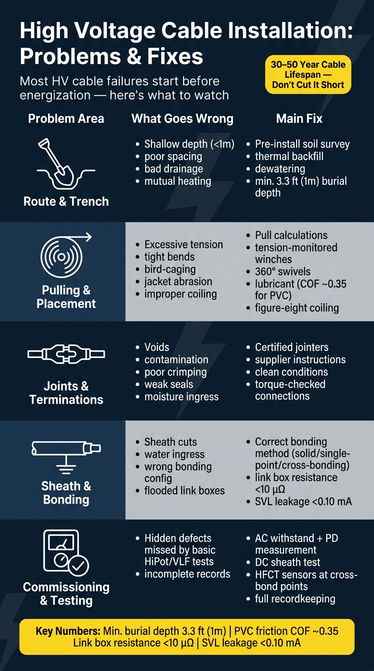
HV Cable Installation: Common Problems, Causes & Fixes at a Glance
How to install High Voltage 132kV Cable underground network
sbb-itb-501186b
Quick Comparison
| Problem area | What usually goes wrong | Main fix |
|---|---|---|
| Route and trench | Shallow depth, poor spacing, bad drainage | Survey soil, set proper depth, use thermal backfill, control water |
| Pulling and placement | High tension, tight bends, twisting, abrasion | Do pull calculations, monitor tension, use swivels, lubricant, proper sheaves |
| Joints and terminations | Voids, dirt, poor seals, bad crimping | Use certified jointers, follow supplier steps, keep work clean |
| Sheath and bonding | Sheath damage, water ingress, wrong bonding setup | Repair sheath correctly, check bonding design, test link boxes and SVLs |
| Commissioning | Hidden defects missed by basic tests | Use AC withstand with PD, sheath testing, and full records |
If I had to sum it up in one line: most HV cable failures start long before energization, and the fix is disciplined installation plus proper testing.
Route Design and Laying Method Problems
Route layout, trench depth, and backfill shape long-term cable performance. Get the trench wrong, and you build in heat, moisture, and mechanical stress from day one. In many projects, the first trouble spots can be traced back to route planning and trench prep.
Problem: Wrong Trench Depth, Utility Separation, and Drainage
Shallow burial is one of the most common early mistakes. Regulatory standards typically require at least 3.3 feet (1 meter) of earth cover over HV cables. That cover helps protect the cable from mechanical damage and lets the system handle fault current safely. Go shallower, and the risk goes up fast.
Crowded duct banks create two problems at once. They make excavation around other utilities more dangerous, and they increase mutual heating between cables. When trench temperature climbs, allowable ampacity drops.
Poor drainage causes a different kind of trouble. Water in the trench can weaken compaction and make the trench less stable over time.
These risks fall when the trench is planned around actual soil conditions, heat flow, and water movement.
Fix: Trench Design Standards, Thermal Backfill, and Water Control
The fix starts before digging. A pre-installation survey should confirm soil type, groundwater table depth, and thermal resistivity before the trench design is locked in . In crowded corridors, vacuum excavation is a smart way to locate existing utilities without hitting them by accident.
Backfill matters just as much. Native excavated soil is often a poor option. Controlled backfill, usually moist sand or lean concrete, can lower thermal resistivity and help move heat away from the cable.
Water control also needs to be planned early. In places with a high water table or weak drainage, dewatering should be built into the job from the start. Reinforced trench supports and dewatering systems help keep the trench stable long enough to achieve proper compaction.
The laying method should match site access, surface loads, and future repair needs.
| Method | Best Use | Heat Performance | Water Control | Repair Access |
|---|---|---|---|---|
| Direct Burial | Rural or open routes | High, with controlled backfill | Requires dewatering and stable compaction | Difficult; full excavation needed |
| Cable-in-Duct | Urban or high-traffic areas | Moderate; limited by air gaps | Ducts can be sealed | Easier; cables pulled without re-excavating |
| Concrete-Encased Duct Bank | Multiple circuits; heavy surface loading | Moderate | High mechanical protection | Moderate |
For crossings, trenchless methods like Horizontal Directional Drilling (HDD) or microtunneling can cut surface disruption. But they only work when the soil and groundwater data are right. If surveys miss groundwater or rocky soil, HDD and microtunneling can fail.
Once the route is set, the next risk shifts to mechanical damage during pulling and placement.
Mechanical Damage During Cable Pulling and Placement
A lot of HV cable failures don’t start years later in service. They start during the pull.
If pulling tension gets too high, bends get too tight, or the cable twists as it moves, you can end up with hidden damage that doesn’t show up right away. That damage can later turn into insulation failure.
Problem: Excessive Pulling Tension and Bending Radius Violations
One of the main trouble spots is sidewall bearing pressure (SWBP). That’s the radial load the cable takes at each bend. It climbs fast, and two 90° bends can deform the armor and insulation, especially when the sheaves are too small.
Twisting is another big issue. Pulling from the middle in opposite directions, or stopping the cable from rotating, can twist the armor into bird-caging. That’s when the armor strands flare outward and split the sheath. Bad coiling makes things worse. Simple loops can create kinks and stress points. Figure-eight coiling helps avoid kinks and core stress.
What makes this tricky is that pull damage can slip past routine HiPot or VLF testing and still lead to partial discharge and early failure years later.
So the job isn’t just “get the cable in the duct.” It’s about controlling pull force, bend shape, and cable rotation from start to finish.
Fix: Pull Planning, Tension Monitoring, and Safe Handling Procedures
Start with pull calculations before installation. Check expected tension, SWBP, and bend radius against the manufacturer’s limits. Then use the right setup: tension-monitored winches, 360° swivel links, proper lubricant, and cleared ducts to cut down torsion, friction, and snagging .
For context, a standard PVC jacket in conduit has a coefficient of friction (COF) of about 0.35. A good lubricant plan can lower friction by a lot.
Sheave selection matters too. Match the sheave size to the cable’s dynamic bend radius, not just the static rating .
| Mechanical Risk | Common Field Cause | Mitigation Method |
|---|---|---|
| Sidewall Pressure | Too many 90° bends; undersized sheaves | Increase bend radii; use larger sheaves and rollers |
| Torsion/Twisting | Pulling without swivels; rope-only pulls | Use 360° swivel links and rotating pulling heads |
| Jacket Abrasion | Duct obstructions; no lubricant | Clear ducts with brushes or foam pigs; apply cable lubricant |
| Bird-Caging | Torsion from mid-point pulling | Ensure cable can rotate freely; use cable socks |
| Insulation Kinks | Improper coiling (simple loops) | Use figure-eight coiling technique |
Jacket checks should happen twice: once before the pull to document any shipping or transit damage, and once after the pull to catch damage caused during installation. And if abrasions on a test pull go past half the depth of the outer sheath, the duct route should be fixed before the full cable pull starts.
Joints, Terminations, and Insulation Integrity Problems
After pulling damage, the next weak spots are usually joints and terminations. This is where workmanship can make or break the cable system.
Problem: Defective Accessories, Sheath Damage, and Water Ingress
Voids, contamination, and poor crimping can create high-resistance defects in joints and terminations. And some of the worst issues start small. A bit of dirt during assembly, a missed step, or a poor seal can leave behind hidden defects that are hard to spot before energization.
Damage to the metallic sheath matters just as much. Cuts or abrasions to aluminum, copper, or lead sheaths remove the cable's barrier against moisture and external damage. Once moisture gets in, insulation degradation speeds up.
That’s part of the problem: many of these issues don’t show up on insulation resistance tests. Partial discharge (PD) testing before energization is more likely to catch them.
In practice, these defects often stay hidden until commissioning tests begin.
Fix: Qualified Installation, Approved Repair Methods, and Correct Sheath Bonding
For joint and termination work, the supplier’s instructions should be the main technical reference. Jointers need certification for the specific voltage class, and they need to follow those instructions closely. That means clean working conditions, torque-checked connections, and seals that have been tested.
Sheath bonding also has a direct effect on system performance. The bonding method controls circulating current, induced voltage, and cable rating. Get it wrong, and losses can go up, cable rating can drop, and safety risks can appear.
"Incorrectly configured sheath bonding systems may lead to cable system failures, including unintended cable rating reductions, additional system losses, and possibly pose safety risks." - CIGRE Working Group B1.50
| Bonding Method | Sheath Current Impact | Induced Voltage Control | Installation Complexity | Typical Application |
|---|---|---|---|---|
| Solid (Multiple Point) Bonding | High circulating currents; can reduce cable rating | Lowest induced voltage | Low | Short runs or where losses are acceptable |
| Single Point Bonding | Zero circulating currents | High induced voltage at the ungrounded end | Low | Short cable sections |
| Cross-Bonding | Significantly reduced circulating currents | Controlled and balanced | High | Long-distance transmission circuits |
After installation, sheath voltage limiters (SVLs) and link boxes should be tested and confirmed watertight before the system is energized. These parts are easy to miss during the rush to finish a job, but they matter. A flooded link box or a failed SVL can undermine the whole bonding setup.
The last step is commissioning tests on joints, terminations, and bonding hardware.
Sourcing Cable Accessories and High Voltage Equipment
It helps to source joints, terminations, link boxes, and SVLs early. Electrical Trader offers electrical components and HV equipment suited to HV cable projects. Even then, the right accessories still need commissioning tests before energization.
Testing, Safety, and Choosing the Right Fix
Problem: Missed Defects, Incomplete Testing, and Unsafe Work Practices
After laying, pulling, and jointing, commissioning is the last shot to catch hidden damage before energization. And that matters because joints and terminations fail much more often than the cable sections themselves. Basic checks can miss those weak points. Partial discharge (PD) testing is far more sensitive, so it can spot damage that installation work may have covered up.
Safety has to come first. Before energization, complete lockout/tagout, review site hazards, confirm PPE, assign a trained crew, and make sure everyone is working from the same plan. A bad handoff or a missed step can undo good test work fast.
Fix: Commissioning Tests, Repair-vs-Replace Decisions, and Recordkeeping
Basic insulation checks are not enough here. For XLPE cables, use AC withstand testing with PD measurement. Do not use DC testing on the main insulation. DC can create space charge and harm XLPE over time. PD measurement should support withstand testing, not stand in for it.
On long runs with many joints, sensor placement matters. Put HFCT sensors at cross-bond points instead of depending only on terminations. That gives you a much better read on where trouble may be hiding.
A DC sheath test helps confirm that the outer sheath was not damaged during pulling or backfill. If leakage current is high, or the sheath-to-earth voltage will not hold, there is likely a fault that needs to be fixed before energization. Link box contact resistance should stay below 10 µΩ, and Sheath Voltage Limiters (SVLs) should be checked to confirm they draw no more than 0.10 mA under DC test conditions.
Unsafe work can turn a good test into a bad cable. Test results should guide the fix, not hunches. Once you find a defect, the next call is simple in theory but not always in practice: repair it, replace a section, or re-pull the full run.
| Option | Outage Impact | Labor Demand | Material Cost | Best-Fit Scenario |
|---|---|---|---|---|
| Localized Repair | Moderate | High - certified jointers required | Low | PD detected at a specific joint or termination |
| Section Replacement | High - excavation required | Very High | Moderate | Localized insulation breakdown in the cable itself |
| Full Re-pull | Very High - full circuit down | Extreme - full crew + heavy machinery | Extreme | Multiple defects or severe pull damage across the run |
Whatever fix is chosen, write it down clearly so the next outage does not start from scratch. Record trench depth, sheath test results, PD maps, link box inspections, grounding and bonding checks, and workmanship certificates in the asset history.
FAQs
How do I know if a cable should be repaired or replaced?
It depends on how bad the damage is and the cable’s overall condition.
Small nicks or scratches on the outer sheath can often be fixed. In many cases, that means cleaning the area and applying sealant patches. If the metallic screen is exposed but still intact, the repair usually calls for a heat-shrink sleeve.
Replacement becomes more likely when the damage goes deeper. That includes cases like:
- compromised armor
- moisture ingress
- internal insulation failure
- advanced age
- partial discharge
- moisture corrosion
So the basic rule is pretty simple: surface damage may be repairable, but deeper wear or internal faults usually point to replacement.
Why is DC testing a poor choice for XLPE cable insulation?
DC testing isn’t recommended for XLPE cable insulation. The main issue is space charge buildup in the solid dielectric. Then, when AC voltage is put back on the cable, those trapped charges can trigger insulation breakdown and damage a cable that was otherwise in good shape.
There’s another problem too: DC testing doesn’t match normal operating conditions. In day-to-day service, these cables run on AC, not DC. So the test can give you a picture that doesn’t line up well with how the cable will perform in the field.
It can also shorten the life of field-aged cables and increase water tree growth. That’s a big reason DC testing is no longer used as often for commissioning and maintenance.
What installation mistakes cause HV cable failures years later?
HV cable failures that show up years later often start with mistakes made on day one. In many cases, the damage happens during handling or installation, including:
- exceeding the manufacturer’s minimum bending radius
- applying too much pulling tension
- exposing cables to high sidewall pressure
Those issues can damage the insulation or deform the armor. And that can lead to problems like bird-caging or sheath splits.
Jointing and termination problems can also come back to bite later. If connectors aren’t mated properly, they can create interface failures or creep paths that get worse over time.


