
Generator Synchronization for Load Balancing
Generator synchronization ensures a generator connects seamlessly to a power system by aligning its voltage, frequency, phase angle, and phase sequence with the grid. Proper synchronization prevents equipment damage, power surges, and mechanical stress. This process is critical for industries like hospitals, data centers, and industrial plants where uninterrupted power is non-negotiable.
Key steps include:
- Voltage Matching: Align generator voltage to within ±3% to ±5% of the system voltage.
- Frequency Matching: Adjust generator speed to match grid frequency with a tolerance of ±0.05 Hz.
- Phase Alignment: Ensure the phase angle difference is near zero for smooth power transfer.
- Post-Synchronization Checks: Verify load sharing, stability, and ensure no protective relays have tripped.
Two load-sharing methods are commonly used:
- Droop Control: Shares load proportionally among generators, allowing slight frequency drops.
- Isochronous Mode: Maintains constant frequency, ideal for standalone systems.
Modern tools like synchroscopes, Automatic Voltage Regulators (AVRs), and sync-check relays enhance safety and precision. Following strict safety protocols and periodic maintenance ensures reliable operation and equipment longevity.
Parallel Operation of AC Generators | synchronizing | Load Sharing
sbb-itb-501186b
Critical Parameters for Generator Synchronization
When synchronizing a generator with a system, aligning voltage, frequency, and phase angle is non-negotiable. Even minor mismatches can lead to equipment damage or activate protective relays. Let’s break down why each parameter is so important.
Voltage Matching
Voltage matching ensures the generator's RMS voltage aligns with the system bus voltage before closing the breaker. If the generator voltage exceeds the grid voltage, it becomes overexcited, exporting reactive power and risking surges. Conversely, a lower generator voltage underexcites it, causing it to absorb reactive power, which can lead to failure.
"If the generator voltage is higher than the grid voltage, this means that the internal voltage of the generator is higher than the grid voltage. When it is connected to the grid the generator will be overexcited and it will put out MVAR." – Edvard Csanyi, Founder of EEP
The Automatic Voltage Regulator (AVR) plays a key role here, adjusting the alternator's excitation current to maintain proper voltage. Industry standards recommend matching voltages within ±3% to ±5% of the system voltage, with synchronism-check relays typically allowing breaker closure only when the difference is around 2% to 5%. Always ensure the AVR is set to automatic and verify the generator terminal voltage using a voltmeter.
Frequency Matching
Frequency matching involves synchronizing the generator's rotational speed with the system frequency. Adjust the prime mover speed to closely match the system frequency, usually setting the generator frequency slightly higher - within a tolerance of ±0.1 to 0.2 Hz. This slight difference allows the generator to immediately take on a positive load upon connection, rather than drawing power from the grid.
Modern systems aim for a frequency difference of less than 0.05 Hz at the moment of breaker closure for smooth synchronization.
"The speed of rotation of the pointer indicates the difference in frequency of the two voltages. The pointer will rotate in the Slow or counterclockwise, direction when the generator frequency is below the grid frequency." – Edvard Csanyi, Electrical Engineer and Founder, EEP
Failing to match frequencies can result in the grid forcing the generator into instant alignment, which can cause severe power oscillations and mechanical stress. To avoid this, monitor the synchroscope and confirm that the needle rotates slowly in the "fast" (clockwise) direction before closing the breaker.
Phase Alignment
Phase alignment ensures the generator's and grid's sine waves are perfectly in sync, enabling smooth power transfer. The phase angle measures the electrical difference between these waveforms, and the breaker should close when this angle is zero.
"Closing the breaker when this angle is zero - meaning the waves are perfectly aligned - ensures a smooth transfer of real power (kW). Closing at any other angle causes a sudden, damaging surge of power as the systems violently snap into alignment." – Gretech Power
To minimize mechanical and electrical stress, aim to keep the phase angle difference under 10° at the moment of closure. The synchroscope needle pointing straight up at 12 o'clock indicates zero phase angle, signaling it's safe to close the breaker. Additionally, confirm that the phase sequence (e.g., A-B-C) matches on both sides. A mismatched sequence results in a 120° phase error, akin to a dead short circuit.
Modern automatic synchronizers further refine this process by calculating an "advance angle" to account for breaker closing times, ensuring the contacts meet at exactly 0°. A synchronism-check relay (ANSI 25) serves as a backup, preventing breaker closure if any parameter deviates from preset limits. With voltage, frequency, and phase angle aligned, you're ready to proceed with synchronization.
Step-by-Step Synchronization Process
Once you've identified the key parameters, the next step is to carefully follow the synchronization procedure. This process demands precision and proper sequencing to prevent equipment damage or system instability.
Step 1: Initial Setup and Parameter Monitoring
Start by ensuring all monitoring tools - such as the synchroscope, dual voltmeters, frequency meters, and sync-check relay - are functioning correctly. Test the synchroscope by running the generator slightly below and then above the synchronous speed. The needle should rotate in the "Slow" direction when the frequency is low and in the "Fast" direction when the frequency is high. If the needle remains stationary despite a large frequency gap, this is normal behavior within a 2 Hz tolerance.
Check the phase sequence using standard testing procedures, especially during installation or after any maintenance work. If the phase sequence is incorrect - indicated by sequential flashing of bulbs instead of simultaneous flashing - shut down the generator and reverse two of the three power leads.
Next, adjust the Automatic Voltage Regulator (AVR) to bring the generator voltage to within ±3% to ±5% of the system voltage. Then, fine-tune the governor to ensure the generator operates slightly above the grid frequency, adhering to the established tolerances. Once these parameters are verified, you can proceed with synchronization.
Step 2: Synchronization Procedure
Observe the synchroscope needle as it rotates clockwise in the "Fast" direction. For manual synchronization, close the breaker as the synchroscope needle approaches the zero phase angle. This timing compensates for the mechanical delay of the breaker, ensuring that the contacts close precisely when the needle is at the 12 o'clock (zero phase angle) position.
Even with manual synchronization, the sync-check relay acts as a safety device, preventing breaker closure if parameters are outside acceptable limits. Modern automatic synchronizers use an "advance angle" to trigger the breaker about 100 milliseconds early, accounting for mechanical delays so that the contacts close exactly at 0°. Always ensure that voltage, frequency, and phase angle align before closing the breaker.
Step 3: Post-Synchronization Checks
After successfully connecting the generator to the grid, perform several checks to confirm proper synchronization. Immediately verify that power, voltage, and frequency remain stable. If the generator's frequency was lower than the grid's at the moment of connection, the grid could drive the generator, causing mechanical stress and potentially activating reverse power relays (ANSI 32).
To stabilize the system, adjust the governor to increase the generator's real power (kW) output, allowing it to take on its share of the load. Control reactive power (MVAR) by modifying the field current or AVR. If the generator's internal voltage exceeds the grid voltage, it will export MVARs (overexcited); if it's lower, it will absorb MVARs (underexcited). Check that no protective relays have tripped, as this would indicate abnormal conditions. These post-synchronization steps are essential for maintaining load sharing and system stability.
| Parameter to Monitor | Control Mechanism | Impact on System |
|---|---|---|
| Real Power (kW) | Governor / Prime Mover Speed | Determines the generator's share of the load |
| Reactive Power (MVAR) | Field Current / AVR | Regulates voltage and power factor |
| Frequency (Hz) | Governor Set Points | Maintains system-wide timing and stability |
| Phase Angle | Synchroscope / Sync-check Relay | Ensures smooth connection without current surges |
When operating multiple generators in parallel, distribute the load based on each unit's capacity rather than splitting it evenly. Additionally, monitor the generator's thermal limits to avoid overheating, as excessive heat can shorten the machine's lifespan significantly.
Load Sharing Methods After Synchronization
Once synchronization is complete, managing load sharing effectively becomes crucial to maintaining system stability. Two primary approaches - droop control and isochronous mode control - are commonly used, each with its own way of handling load changes.
Droop Control Method
In the droop control method, a generator's speed and frequency decrease as the load increases. For example, in North America, power plants often use a 4% or 5% droop setting. If a generator operates with a 5% droop, it will run at around 105% of its rated speed when unloaded and 100% when fully loaded. This approach allows generators to share the load proportionally to their power ratings without requiring direct communication between units. The governor adjusts the fuel input based on the difference between the generator's preset speed reference and the actual grid speed.
By standardizing droop settings across all units, the system ensures proportional load distribution. However, this method comes with a trade-off: the frequency can vary slightly, which might impact power quality to some extent.
Isochronous Mode Control
Isochronous mode, on the other hand, keeps the system frequency constant - usually at 50 Hz or 60 Hz - regardless of load changes. In this mode, the speed governor continuously and rapidly adjusts the prime mover's speed to counter fluctuations in load demand. When multiple generators operate in parallel, isochronous controllers calculate the load each unit should handle as a percentage of the total system load. Modern digital controllers ensure precise load sharing, typically maintaining active power sharing within ±2.0% of the rated power and reactive power sharing within ±5.0%, with data exchanged via CANbus every 50–100 milliseconds.
However, isochronous systems require identical governors and communication interfaces to function smoothly. Without proper load-sharing controllers, generators might "compete" to handle load changes, which could destabilize the system or even cause unintended trips. Isochronous mode is particularly suited for situations where maintaining a precise frequency is critical, such as in military bases or industries with sensitive equipment. For systems with generators of varying sizes or from different manufacturers, droop control is often the more practical solution.
The choice between these methods depends on the specific requirements of the application and the system's configuration. Each method has its strengths and trade-offs, making them suitable for different scenarios.
Droop Control vs. Isochronous Mode Comparison
Droop Control vs Isochronous Mode Generator Synchronization Comparison
Choosing between droop control and isochronous mode depends on your specific needs: natural load sharing or precise frequency regulation. Each approach tackles load changes differently, making them suitable for distinct applications.
Droop control works by allowing a controlled frequency drop - usually between 3% and 5% - as the load increases. This method enables multiple generators to share the load proportionally without needing direct communication between units. Its simplicity makes it the go-to option for setups with multiple generators or systems connected to a utility grid.
On the other hand, isochronous mode keeps the frequency locked at exactly 50 Hz or 60 Hz, regardless of load changes. The governor reacts instantly to maintain this constant frequency, making it a better fit for standalone generators or equipment that demands precise frequency control, such as certain medical devices or military electronics.
However, isochronous mode presents challenges when multiple units operate in parallel. Without a dedicated load-sharing controller, these units will compete with each other, leading to instability. Digital controllers, using CANbus communication every 50 to 100 milliseconds, can solve this issue by ensuring active power sharing stays within ±2.0% of the rated power. Without such communication, problems are inevitable.
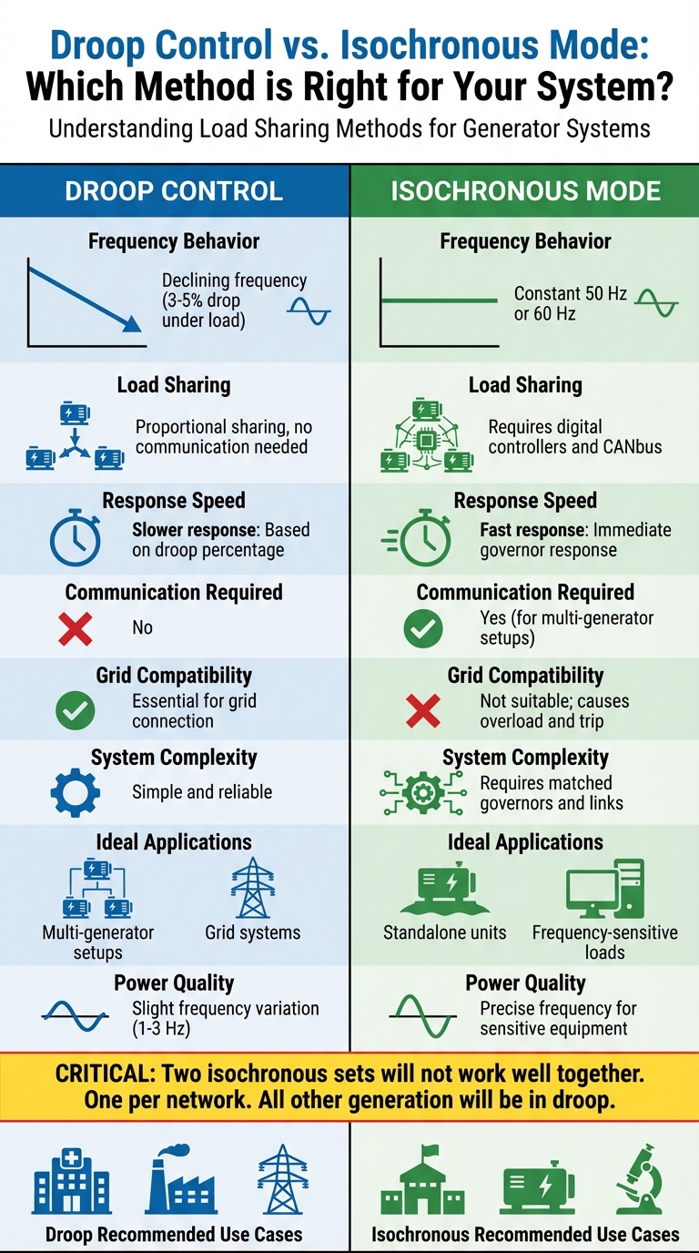
"Two isochronous sets will not work nor play well with each other. One per network. ALL OTHER GENERATION WILL BE IN DROOP."
For grid-connected systems, droop control is a must. An isochronous generator attempting to stabilize the entire grid's frequency will quickly overload and shut down. In isolated systems where frequency stability is critical, operators often rely on one large "swing" generator running in isochronous mode for frequency regulation. Other generators in the system typically operate in droop mode to handle base load requirements.
Understanding how these methods function ensures your system is both stable and efficient. The table below highlights the key differences between droop control and isochronous mode for easy reference.
Comparison Table
| Feature | Droop Control | Isochronous Mode |
|---|---|---|
| Frequency Behavior | Controlled drop under load (3-5%) | Constant at 50 Hz or 60 Hz |
| Load Sharing | Proportional sharing, no communication | Requires digital controllers and CANbus |
| Response Speed | Slower, based on droop percentage | Immediate governor response |
| Communication Required | No | Yes (for multi-generator setups) |
| Grid Compatibility | Essential for grid connection | Not suitable; causes overload and trip |
| System Complexity | Simple and reliable | Requires matched governors and links |
| Ideal Applications | Multi-generator setups; grid systems | Standalone units; frequency-sensitive loads |
| Power Quality | Slight frequency variation (1-3 Hz) | Precise frequency for sensitive equipment |
Tools and Equipment for Generator Synchronization
To synchronize a generator successfully, you need tools that can precisely monitor and adjust voltage, frequency, and phase angle. Using the right equipment ensures proper alignment and helps protect the system from damage or instability.
One essential tool for manual synchronization is the synchroscope. This device shows the frequency differences and phase alignment between the incoming generator and the grid. When the needle reaches the 12 o'clock position, it indicates a zero-phase angle - signaling the perfect moment to close the circuit breaker .
The Automatic Voltage Regulator (AVR) and the engine governor (speed controller) are also vital. The AVR adjusts the generator's excitation current to match the bus voltage, while the governor controls fuel input to maintain the correct frequency and make small tweaks to the phase angle . These tools work together to keep the system stable and aligned.
For added safety and automation, a sync check relay (ANSI Device 25) ensures the circuit breaker won’t close unless voltage, frequency, and phase angle meet preset conditions . More advanced setups may use an auto-synchronizer (ANSI Device 25A), which communicates with both the governor and the AVR to make precise, real-time adjustments. Once all parameters are aligned, it automatically closes the breaker . The circuit breaker itself serves as the final connection point to link the synchronized generator with the grid or live bus .
In addition to these advanced tools, basic instruments provide essential real-time monitoring. Voltmeters and frequency meters confirm voltage and frequency levels during operation . For installations or post-maintenance checks, phase sequence indicators - including the classic three-light-bulb method - verify correct rotation, reducing the risk of short circuits when the breaker closes .
Electrical Trader offers a wide range of synchronization tools to help ensure operations remain safe and efficient.
Best Practices and Safety Guidelines
Synchronizing a generator isn't just about following a procedure - it requires strict adherence to safety protocols. A misstep, like closing out of sync, can lead to severe consequences. Circulating currents could surge to several times the generator's rated capacity, potentially destroying stator windings or even snapping rotor shafts. The IEEE Power System Relaying and Control Committee emphasizes, "A synchronizing system that is designed and verified to operate within a generator's synchronizing limits is critical in helping maintain the life of generating plant assets and improving stability of the power system".
Double-check phase sequence during the initial setup or after maintenance involving power leads or potential transformers. Getting the phase sequence wrong could cause an immediate short circuit when the breaker is closed. These checks are essential alongside the synchronization steps already outlined.
Leverage automatic synchronization whenever possible to minimize human error. As electrical engineer Edvard Csanyi explains, "Electrical and mechanical systems have become less tolerant of the rough synchronization of impatient or inattentive operators as generator sizes have grown and designs have become more efficient". Manual synchronization, while still an option, demands extreme care. Prematurely closing the breaker or exceeding acceptable slip frequency can result in damaging mechanical shocks and electrical surges. IEEE Standards C50.12 and C50.13 outline strict synchronization limits: an angle within ±10 degrees, voltage deviation between 0 and +5 percent, and a slip frequency under 0.067 Hz (equivalent to a synchroscope spinning at 4 rpm).
Keep generator loads between 30% and 70% of their rated capacity for optimal performance and stability. Avoid running the generator under no-load conditions for more than 15 minutes, as this can lead to engine damage. After removing the load, let the generator run at no load for 5 minutes before shutting it down. Performing an annual Load Bank Test is also crucial. This test runs the generator under load for several hours, clearing out deposits and ensuring the system operates as expected.
Install safeguards to detect and respond to failures. Systems should immediately trigger alarms or shut down if they sense breaker failures, overcurrent, loss of field excitation, reverse power, overspeed, or ground faults. For added protection, always wire the Sync-check relay (ANSI Device 25) in series with manual control switches. This ensures the breaker won't close unless all parameters are within safe limits. Such layered supervision is vital for safeguarding equipment and personnel during synchronization.
Conclusion
Generator synchronization is the backbone of a stable and reliable power system. When executed properly, it ensures multiple generators operate as a cohesive unit, sharing loads efficiently while protecting critical equipment from potential damage. As Richard C. Schaefer highlights in IEEE Transactions on Industry Applications:
"Proper synchronization provides... minimum mechanical and electrical shock to the oncoming generator; monetary benefits from enhanced equipment longevity; [and] rapid loading of the oncoming generator".
Even a single synchronization error can lead to severe consequences, such as transformer damage, rotor shaft failure, or even cascading system breakdowns. This makes it crucial to align voltage, frequency, phase sequence, and phase angle with precision.
Modern digital synchronizers address the risks associated with manual synchronization, offering the accuracy and safeguards required for today’s complex power systems. These tools are especially valuable in high-pressure scenarios where human error is more likely.
Whether you're ensuring uninterrupted power for a hospital, balancing industrial loads, or maintaining grid stability, the process remains fundamentally the same. Every step - precise parameter matching, phase sequence verification, and thorough post-connection checks - plays a role in maintaining a dependable power system. By keeping loads between 30% and 70% for efficiency, verifying phase sequences after maintenance, and never overlooking post-synchronization checks, you not only safeguard your equipment but also ensure uninterrupted power for critical operations.
FAQs
What happens if a generator closes out of sync?
If a generator shuts down out of sync, it can cause serious problems like system disturbances, power surges, and damage to both the generator and any connected equipment. These disruptions can undermine system reliability and potentially lead to expensive repairs or even equipment replacement.
When should I use droop control vs isochronous mode?
Use isochronous mode in scenarios where maintaining a precise and steady frequency is critical, such as in isolated or off-grid power systems. This mode adjusts the generator's speed to keep the frequency stable, ensuring consistent power quality.
Opt for droop control in systems with multiple generators running in parallel. This approach allows for proportional load sharing by tolerating minor frequency variations, which helps prevent overloading and ensures stable operation even when loads fluctuate.
Which protective relays are most important during synchronization?
The most important protective relays during synchronization are the ones that monitor generator voltage and frequency. These relays play a key role in ensuring the generator stays within safe operating limits, helping to avoid any potential damage during the synchronization process.