




Data Center UPS Sizing: 5 Planning Steps
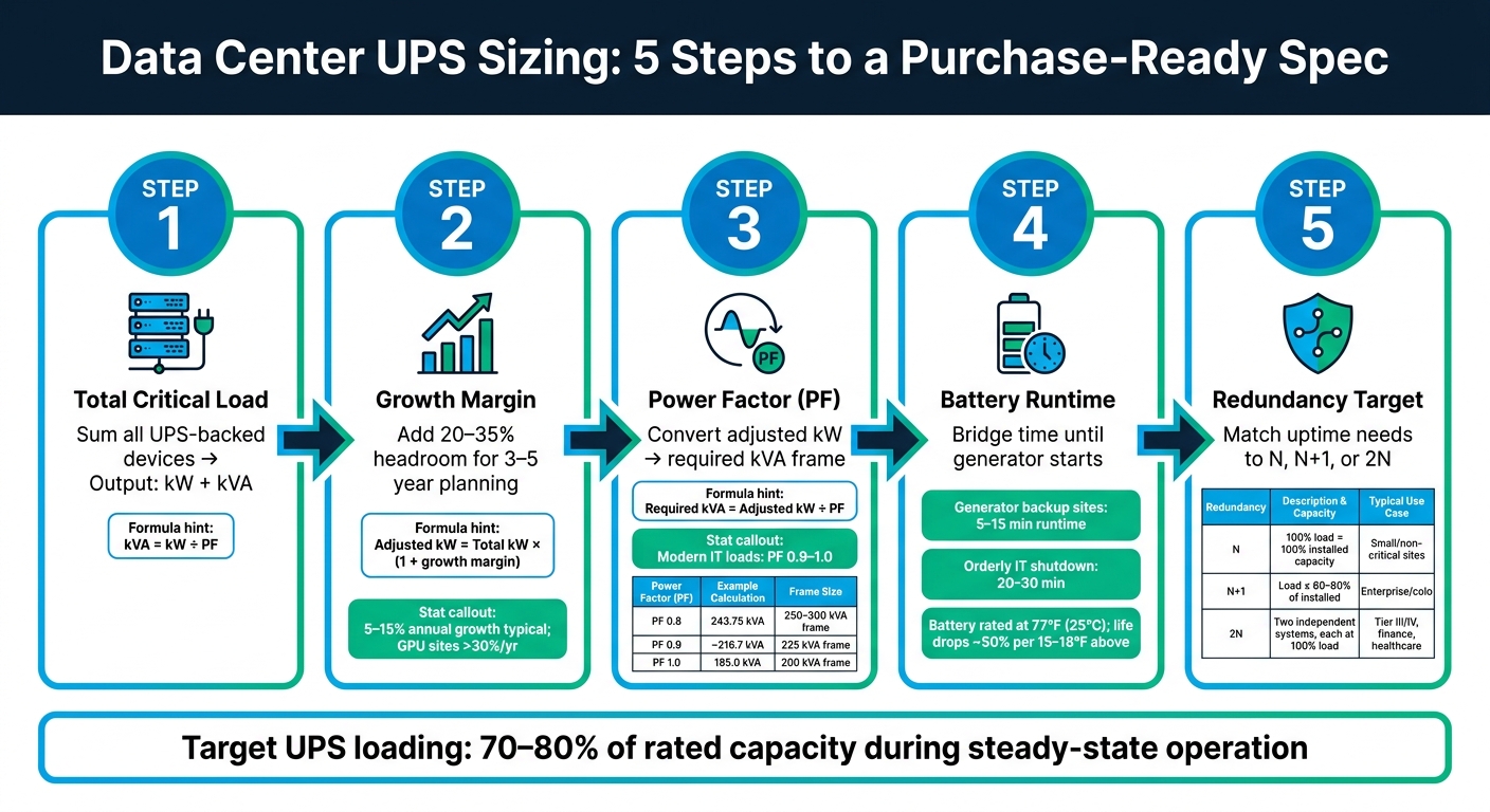
Get UPS sizing wrong, and you risk either outages or wasted spend. The article boils the job down to five planning steps: total load, growth margin, power factor, battery runtime, and redundancy.
If I had to sum it up in one line, it would be this: start with measured kW, add 20%–35% headroom, convert to kVA using the right PF, set runtime around 5–15 minutes if generators are on site, then choose N, N+1, or 2N based on uptime needs.
Here’s the whole process at a glance:
- Step 1: List every UPS-backed device and total the load in kW and kVA
- Step 2: Add growth margin for the next 3–5 years
- Step 3: Check power factor, because it changes the UPS frame size
- Step 4: Set battery runtime based on generator start time, transfer delay, and shutdown time
- Step 5: Pick a redundancy level: N, N+1, or 2N
A few numbers stand out:
- Modern IT loads often run at 0.9 to 1.0 PF
- Many U.S. data centers target 5–15 minutes of runtime with generator backup
- A common UPS loading target is 70%–80% in normal use
- Fast-growing sites may see 5%–15% annual load growth, while GPU-heavy sites can go past 30% per year
This article is useful if you want to turn a rough estimate into a purchase-ready UPS spec without overbuilding or coming up short.
Data Center UPS Sizing: 5-Step Process Guide
Quick Comparison
| Planning step | What I need to decide | Main output |
|---|---|---|
| 1. Critical load | What must stay up | Total kW and kVA |
| 2. Growth margin | How much load may be added | Adjusted planning kW |
| 3. Power factor | How kW maps to UPS rating | Required kVA frame |
| 4. Runtime | How long batteries must carry load | Battery minutes and cabinet count |
| 5. Redundancy | How much backup capacity is needed after a fault or during service | N, N+1, or 2N design |
My takeaway: the article is less about picking a UPS model and more about writing a clear sizing basis. Once those five inputs are set, vendor quotes get much easier to compare.
sbb-itb-501186b
Step 1: Calculate the Total Critical Load
Start by figuring out the full UPS-backed load in kW and kVA. This is your baseline. It shapes every next call you make, including growth, power factor, runtime, and redundancy.
Build a Load Inventory for UPS-Backed Equipment
Write down every device that cannot go offline during an outage or transfer. That usually includes servers, storage, network gear, network security, monitoring, and critical controls.
Leave out office receptacles, lighting, convenience outlets, and noncritical mechanical loads. Generator-backed loads should only stay on the list if they must remain live during the short gap before the generator starts.
It helps to group equipment by subsystem so you don't miss anything. Some items slip through the cracks more often than you'd think. PoE switches and monitoring gear are easy to overlook, but they can stack up fast.
Convert Nameplate and Measured Data into kW and kVA
Next, convert each line item into kW and kVA. If you have measured data from PDU logs or branch circuit monitors, use that first. If not, fall back to nameplate data, then confirm it with metering before final procurement.
Use these formulas:
- kW = watts ÷ 1,000
- kVA = kW ÷ PF using the load's power factor
- For single-phase loads: kVA = (V × A) ÷ 1,000
- For three-phase loads: kVA = (√3 × V × A) ÷ 1,000
Use the three-phase formulas for 208 V and 480 V circuits. Also, record the actual supply voltage for each load. Watts by themselves don't tell the whole story.
After that, add up the loads by subsystem, then roll them into one total kW and kVA number. In one published data center project, the total UPS-backed IT load came to 232.05 kW, and the team chose 240 kVA of UPS capacity. That's a good example of how calculated totals often get rounded up to match available UPS sizes.
That total kW and kVA figure becomes the starting point for growth margin. Step 2 builds from this base and adds planned headroom.
Step 2: Add Growth Margin and Step 3: Confirm Power Factor
Apply a Growth and Headroom Percentage
Once you’ve nailed down the total critical load, add some growth before tying that number to an actual UPS frame size.
Use this formula:
Adjusted kW = total critical kW × (1 + growth margin)
Say your Step 1 total is 150.0 kW and you use a 30% growth margin. Your planning load becomes 150.0 × 1.30 = 195.0 kW. That adjusted number is the one you should use when picking the UPS frame.
Most U.S. data centers plan for about 20–35% headroom. For stable loads, a 3–5 year planning window usually makes sense. For sites growing fast, you may need more. Many data centers see 5–15% annual load growth under normal conditions, and high-density GPU workloads can go past 30% per year. Headroom also helps cover imbalance, inrush, and surprise load adds.
A common target is to run a UPS at 70–80% of rated capacity during steady-state operation. That keeps the unit in its efficient range and still leaves room for spikes.
Write down your assumptions in plain terms. A procurement note could look like this: "Total critical load (Step 1): 175.0 kW; Growth margin (Step 2): 25% (0.25); Adjusted planning load: 218.75 kW; Calculation date: 08/17/2026."
After that, take the kW planning load and convert it into the kVA rating the UPS has to support.
Use Power Factor to Match kW Demand to UPS kVA Rating
Use power factor, or PF, to turn the adjusted kW load into the UPS kVA rating you need.
The formula is simple: required kVA = adjusted kW ÷ power factor
Using the 195.0 kW adjusted load:
| Power Factor Assumption | Required UPS kVA | Typical UPS Frame |
|---|---|---|
| 0.8 PF | 243.75 kVA | 250–300 kVA frame |
| 0.9 PF | ~216.7 kVA | 225 kVA frame |
| 1.0 PF (unity) | 195.0 kVA | 200 kVA frame |
This is where sizing can shift fast. The same 195.0 kW load might push you into a 300 kVA frame or let you fit into a 200 kVA frame, based only on the PF assumption.
Modern double-conversion UPS systems are more often unity power factor rated. That matters. An older 0.8 PF unit labeled "200 kVA" can supply only 160 kW of real power, while a unity PF unit with that same label can supply the full 200 kW.
Before you lock in a model, check the datasheet for:
- kVA output rating
- kW output rating
- PF value
If the UPS kW rating isn’t listed plainly, ask the vendor. The kVA label by itself does not tell you what the unit can deliver to the load.
Once kW and kVA are set, runtime and redundancy drive how much battery and backup capacity you’ll need.
Step 4: Define Battery Runtime and Step 5: Set the Redundancy Target
With kW, kVA, and PF in place, set battery runtime first. Then lock in the redundancy target.
Set Runtime Based on Generator Support and Shutdown Needs
Runtime and redundancy have a big effect on battery count, floor space, and the way the system is built.
UPS batteries are a bridge, not a long-term power source. Most U.S. data centers aim for 5–15 minutes of full-load runtime to cover generator cranking, ATS transfer delays, and allowed start attempts. If a site needs time for an orderly IT shutdown - flushing database logs, closing applications, and finishing failover - it often aims for 20–30 minutes.
To choose the right number, add up:
- your generator’s documented start time
- ATS transfer delay
- allowed start attempts
- the time your shutdown runbook actually needs
Use the longest case, then add a buffer. That gives you your minimum runtime target.
More runtime sounds safer, but there’s a catch. Failures still happen even at 45 minutes of autonomy. And once you get past 10–15 minutes, extra runtime starts to hit hard on cost, space, and cooling.
Two physical limits usually put a ceiling on runtime:
- Temperature: Many UPS batteries are rated at 77°F (25°C), and VRLA service life can drop by about half for every 15–18°F above that point. Keep battery areas between 68–77°F and confirm that your cooling system can hold that range.
- Weight and space: Battery cabinets can weigh several hundred to more than 1,000 lb, and longer runtime means more cabinets, more square footage, and higher floor loading. Check your floor’s lb/ft² rating before you commit, especially in older buildings or raised-floor spaces.
Translate N, N+1, and 2N Goals into UPS Capacity Requirements
Once runtime sets battery duration, redundancy sets how much UPS capacity must still be available after a failure or during maintenance.
Here’s the basic mapping:
- N: Capacity equals load.
- N+1: One extra full-rated module beyond load.
- 2N: Two independent UPS systems, each sized for 100% of critical load.
Use these definitions to connect redundancy level to installed capacity and usable capacity.
| Redundancy Level | Example UPS Configuration | Usable Capacity | Typical Application |
|---|---|---|---|
| N | One 500 kW UPS system | ~500 kW of 500 kW installed | Small sites, labs, or non-critical IT where brief outages are acceptable |
| N+1 | Three 250 kW modules (750 kW total), loaded to 500 kW | ~500 kW of 750 kW installed; one module held in reserve | Enterprise and colocation sites needing high availability with maintenance flexibility |
| 2N | Two independent 500 kW UPS systems on separate A/B paths | ~500 kW usable; 1,000 kW total installed | Tier III/IV–style, financial, healthcare, and cloud facilities requiring maximum uptime |
In N+1 designs, cap steady-state load at 60–80% of installed kW. That gives you room for one module to drop out while the rest keep carrying the load.
In 2N designs, each side supports the full load on its own. That also means more batteries, more floor space, and more cabling than a single-system design.
Redundancy level also affects maintenance. With N+1, you can take one module offline for service while the others keep the load up. With 2N, you can take an entire UPS system down while the parallel system carries all critical equipment.
Record the redundancy target in the sizing document. State the level, the maximum steady-state load, and whether N refers to a module, a frame, or a full system. That one detail can save a lot of back-and-forth when vendors reply to your spec.
Conclusion: Turn the 5 Sizing Steps into a Purchase-Ready Specification
After you’ve gone through all five steps, you’re no longer working with a ballpark figure. You have the inputs needed to write a vendor specification that’s ready for purchase. That means listing your total critical load, growth-adjusted kW, assumed power factor, required kVA, runtime target, and redundancy target. Then map those numbers to the vendor’s rating language: kW, kVA, runtime, voltage, and redundancy.
You should also spell out input/output voltage, frequency, neutral/grounding configuration, and available fault current so the UPS fits cleanly with generators, switchgear, and PDUs.
For sourcing breakers, transformers, switchgear, transfer switches, and distribution panels, Electrical Trader offers a marketplace of new and used electrical equipment matched to your spec requirements.
Use the checklist below to screen proposals before you ask for quotes.
Pre-Purchase Validation Checklist
| Validation Item | What to Confirm |
|---|---|
| Capacity | Vendor usable kW/kVA meets or exceeds the growth-adjusted design load at the assumed PF |
| Battery runtime | Guaranteed minutes at your named operating load and 77°F (25°C) ambient temperature |
| Redundancy model | One-line diagrams show N, N+1, or 2N configuration with correct usable capacity after a defined failure |
| Electrical fit | Input/output voltages, breaker ratings, and available fault current match switchgear and PDU specs |
| Space and weight | Room size, floor loading, clearances, and ventilation are confirmed for the proposed system |
| Compliance | UL listings, NEC coordination study, and any local AHJ requirements are addressed |
| Acceptance testing | FAT and SAT include a load test at expected operating kW and runtime |
FAQs
Should I size the UPS from measured load or nameplate data?
Yes - but only as a starting point.
Nameplate data can help you gather voltage, current, and power factor. But it doesn’t always show the load your UPS will see day to day. In many cases, actual UPS load is lower than the nameplate rating, and some connected devices may not be included at all.
The better move is to measure actual power use under normal operating conditions. That gives you a clearer picture of what the UPS needs to support.
If you’re working from nameplate data, convert to usable kW with kVA × PF. Then add a 20%–25% safety and growth margin so you’re not sizing too close to the edge.
How much headroom is enough for future data center growth?
Plan UPS headroom with a 20%–25% buffer above your current calculated load. In many cases, that gives you room for about 5–10 years of growth.
A common rule of thumb is around 15% growth over five years. That’s why some teams size UPS capacity with a 1.20–1.25 multiplier. It’s a simple way to leave breathing room instead of cutting things too close.
Redundancy changes the math a bit. In a 2N setup, don’t run each UPS too hard. Each unit should usually stay below 50% load, so if one side drops, the other can take the full transfer load without overloading.
When should I choose N, N+1, or 2N redundancy?
Choose based on your budget, risk tolerance, and the cost of downtime.
- N: Lowest cost. Best for non-critical loads where downtime is acceptable.
- N+1: A middle ground between cost and reliability. It adds one spare component, which helps protect against a single-module failure and lets you handle maintenance without losing power.
- 2N: Highest fault tolerance. It duplicates the full power system with separate A and B paths for mission-critical facilities.





